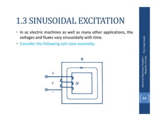
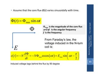
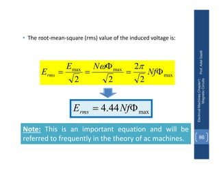
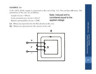
This document provides an overview of magnetic circuits and concepts relevant to electric machines. It discusses:
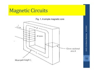
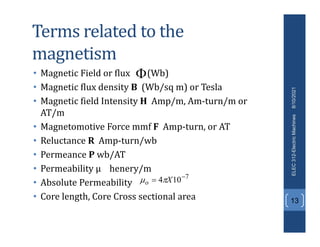
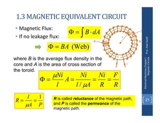
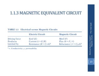
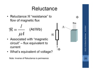
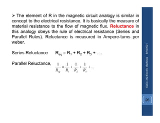
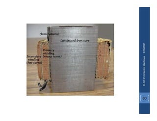
1. Magnetic materials and circuits, defining terms like magnetic flux, flux density, magnetic field intensity, reluctance, and permeance.
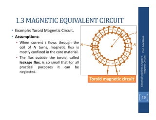
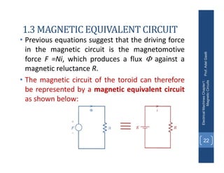
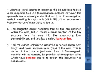
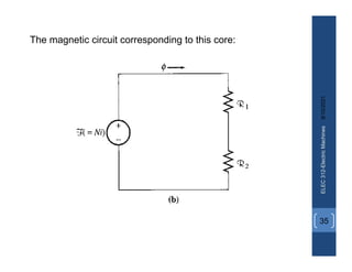
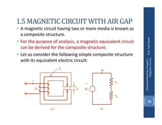
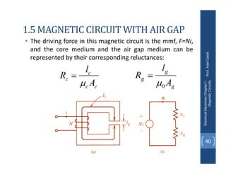
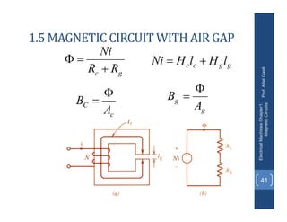
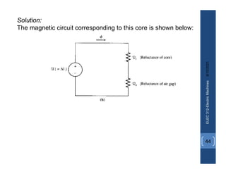
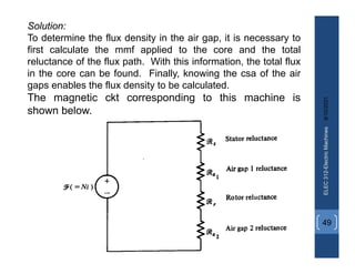
2. How to model magnetic circuits using an equivalent circuit approach, with magnetomotive force driving flux against reluctance.
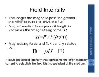
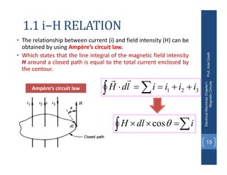
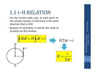
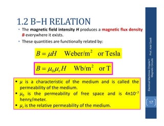
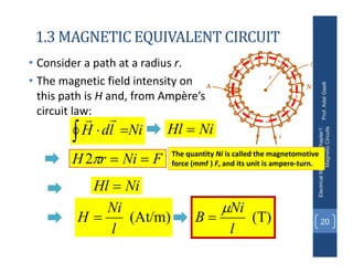
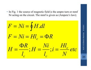
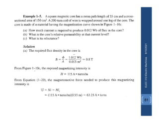
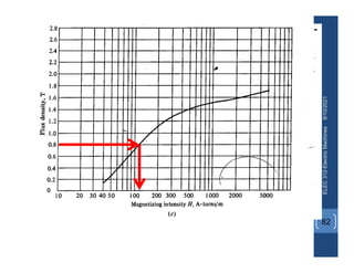
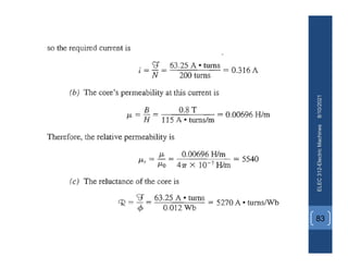
3. Key relationships like between current and magnetic field intensity defined by Ampere's law, and between field intensity and flux density defined by the material's permeability.