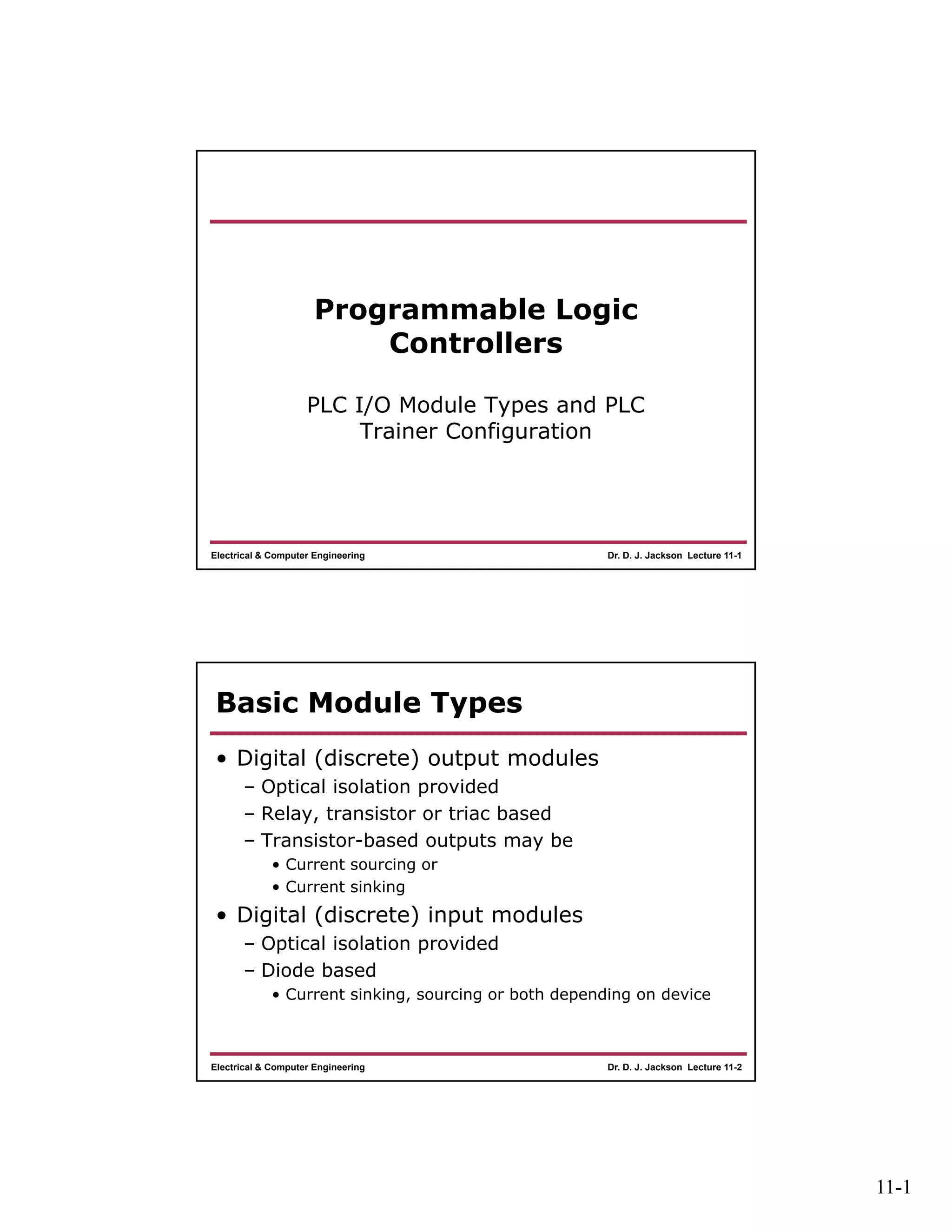
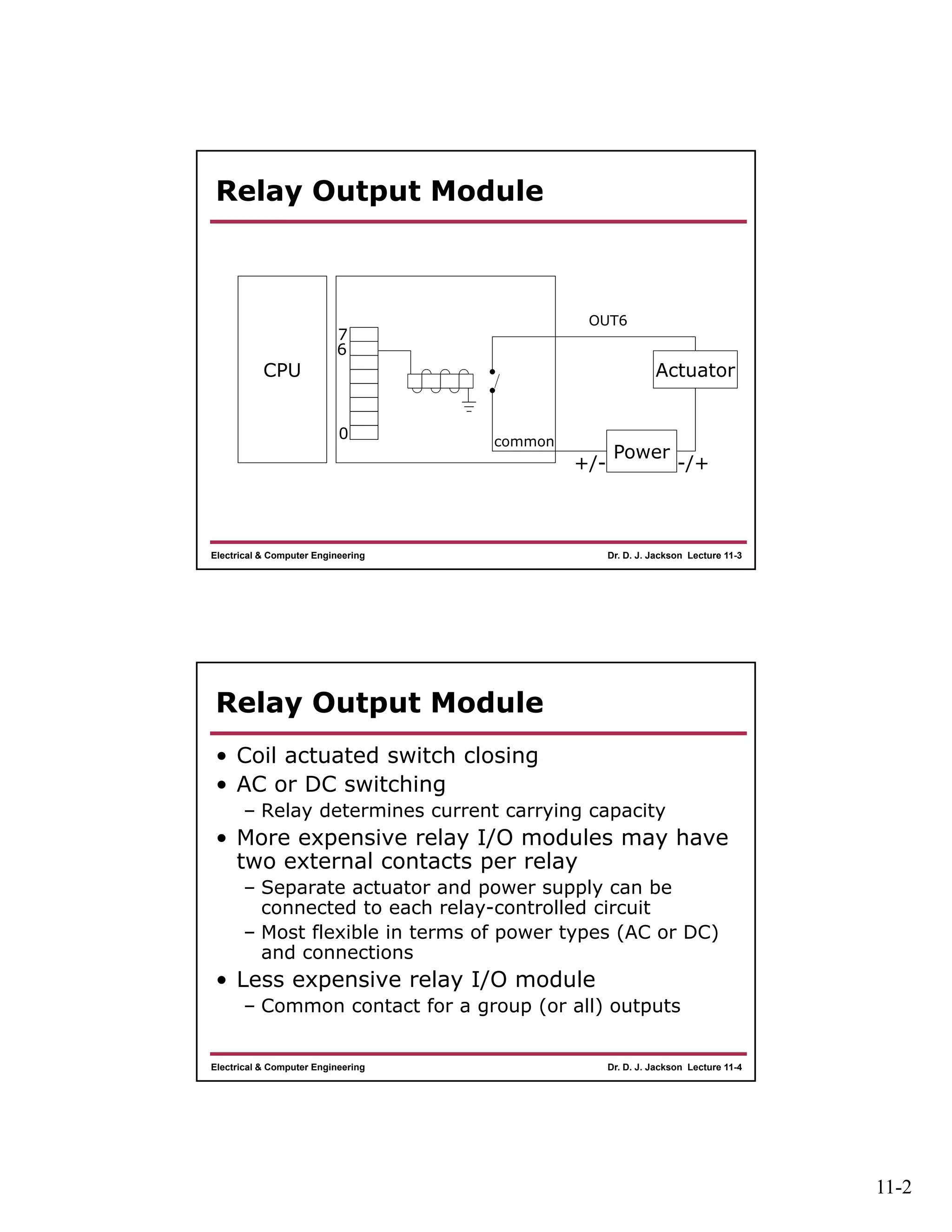
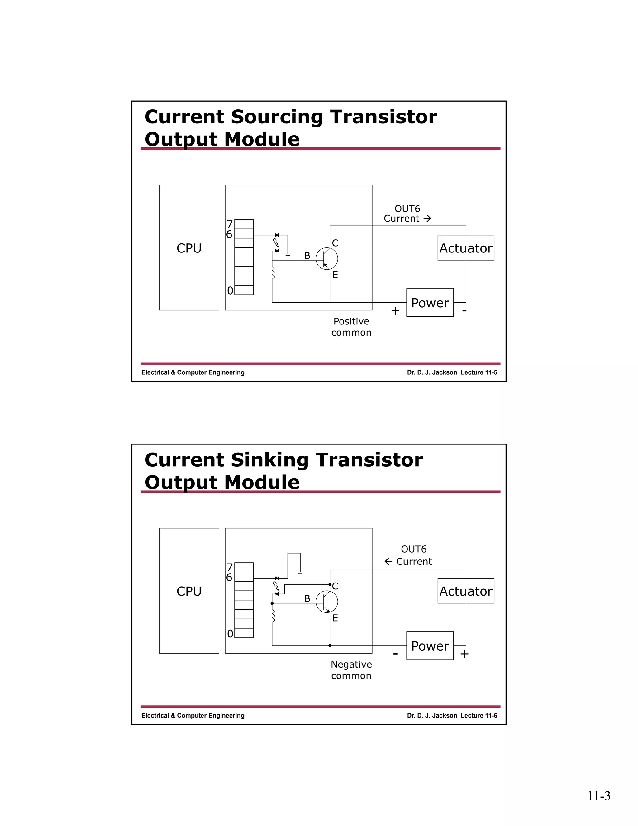
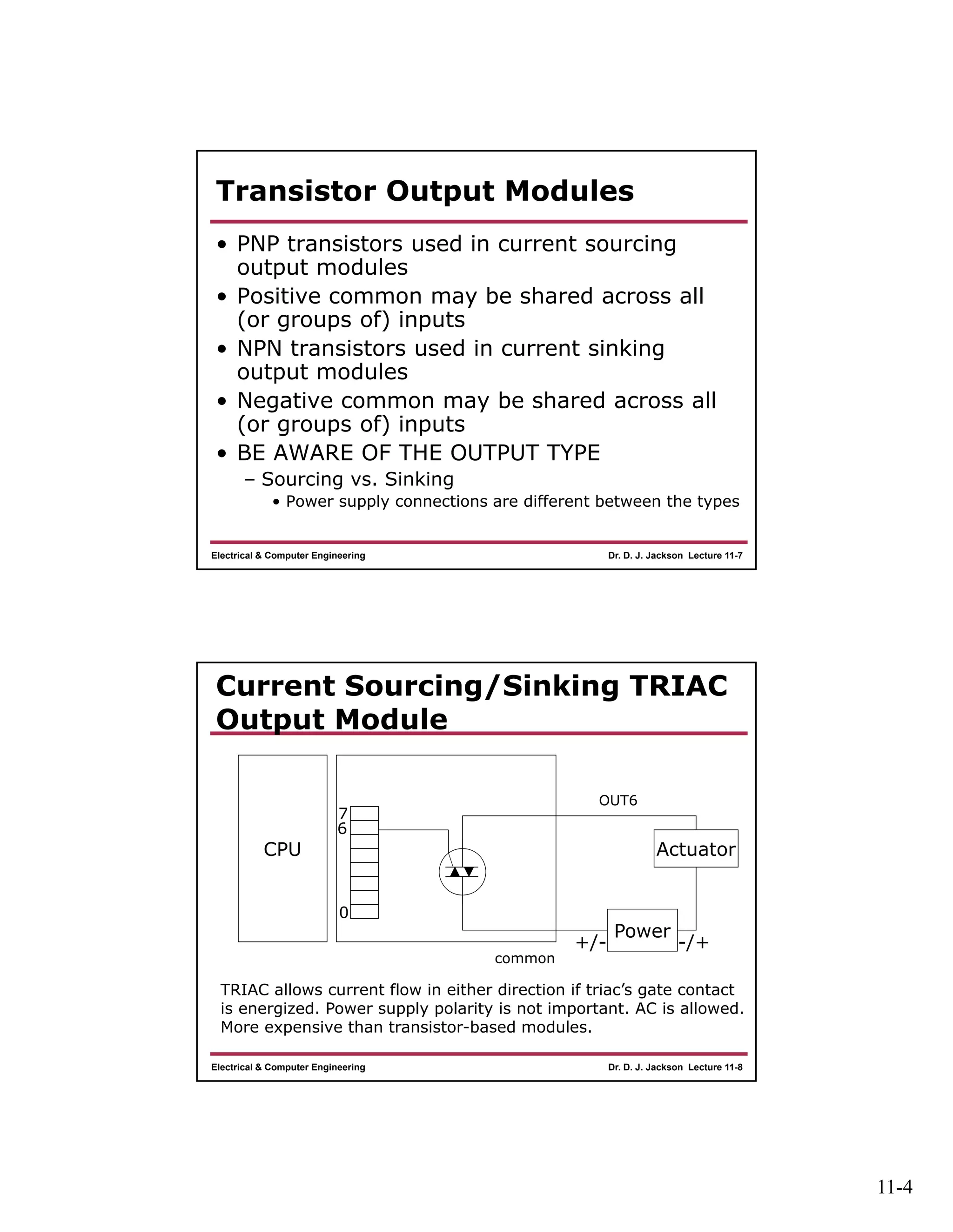
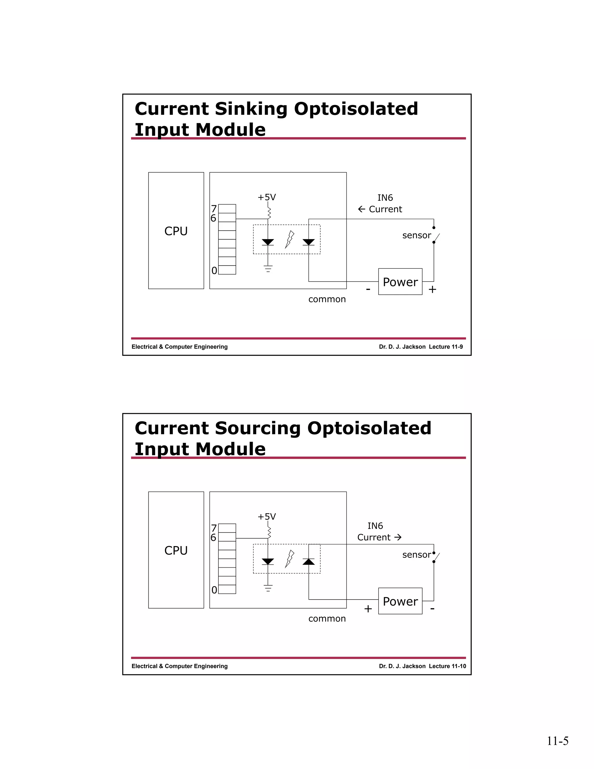
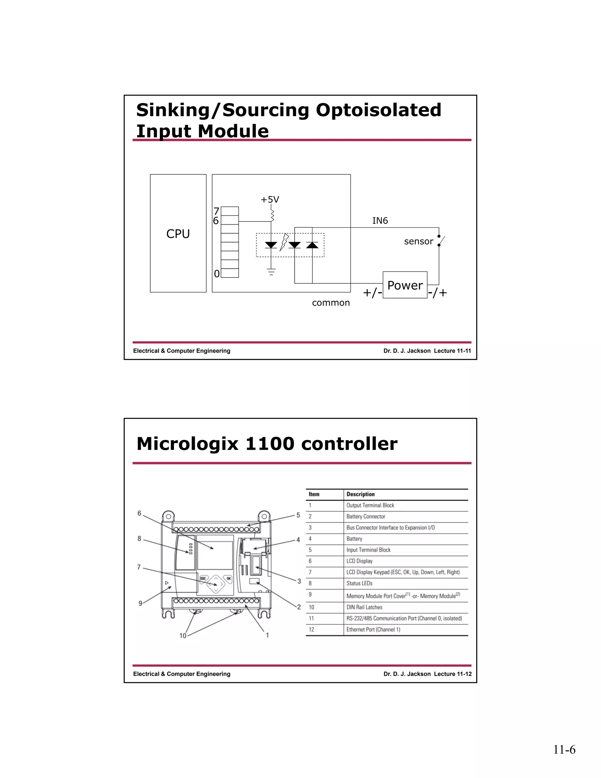
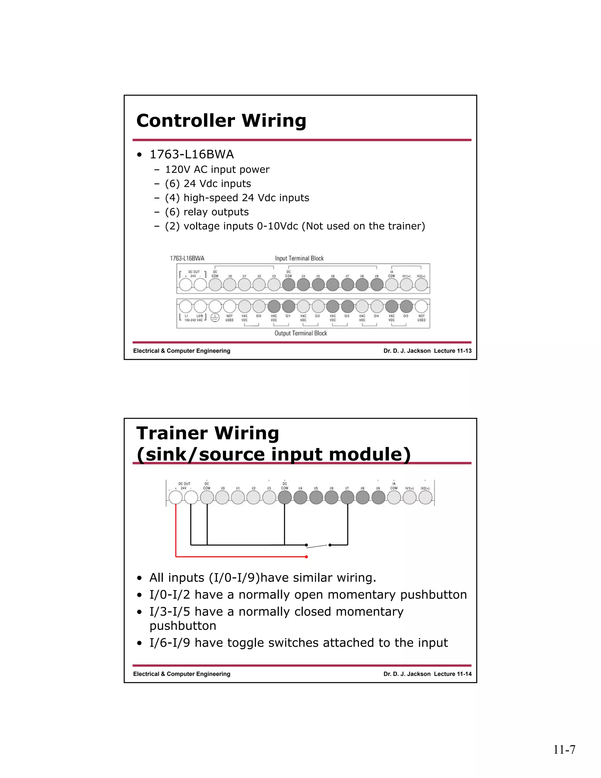
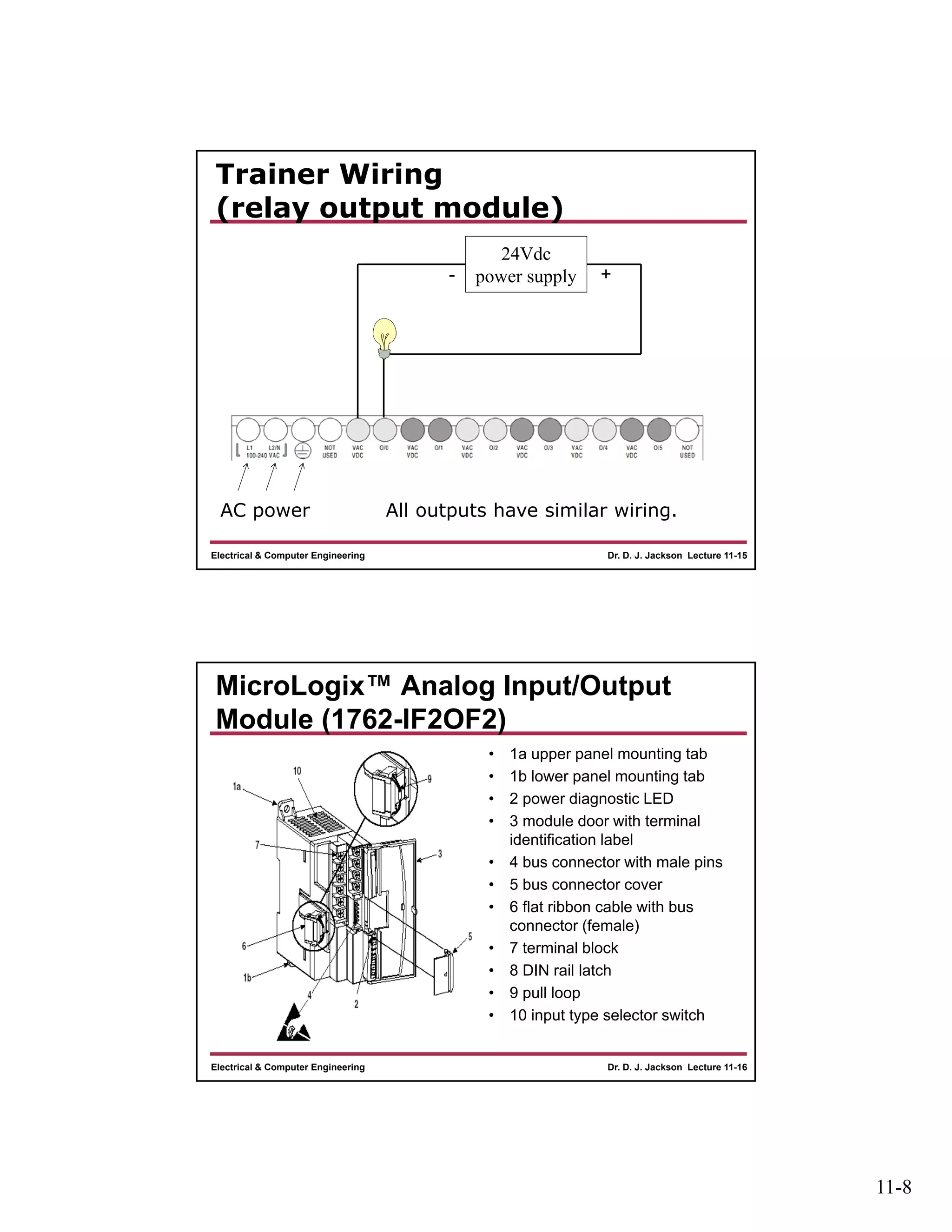
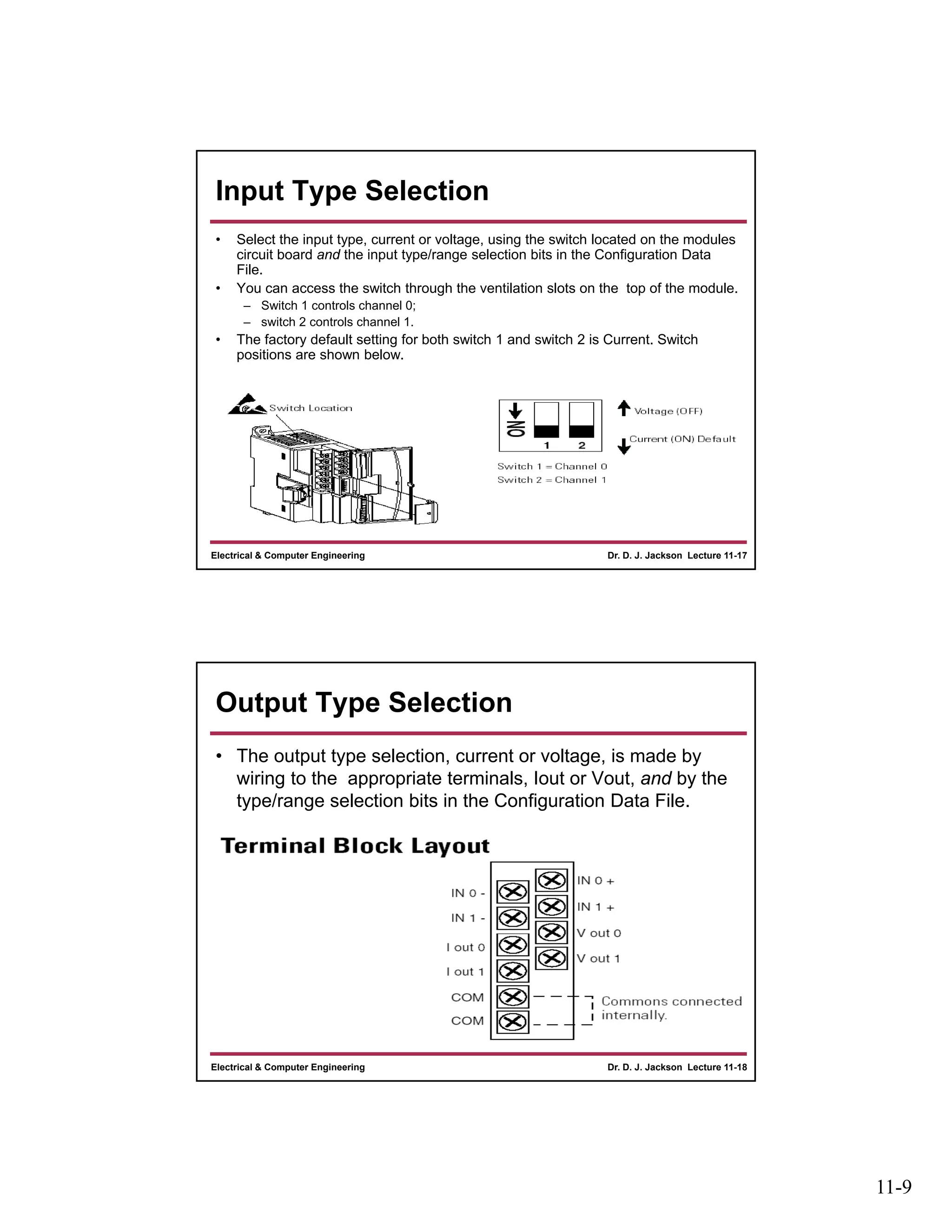
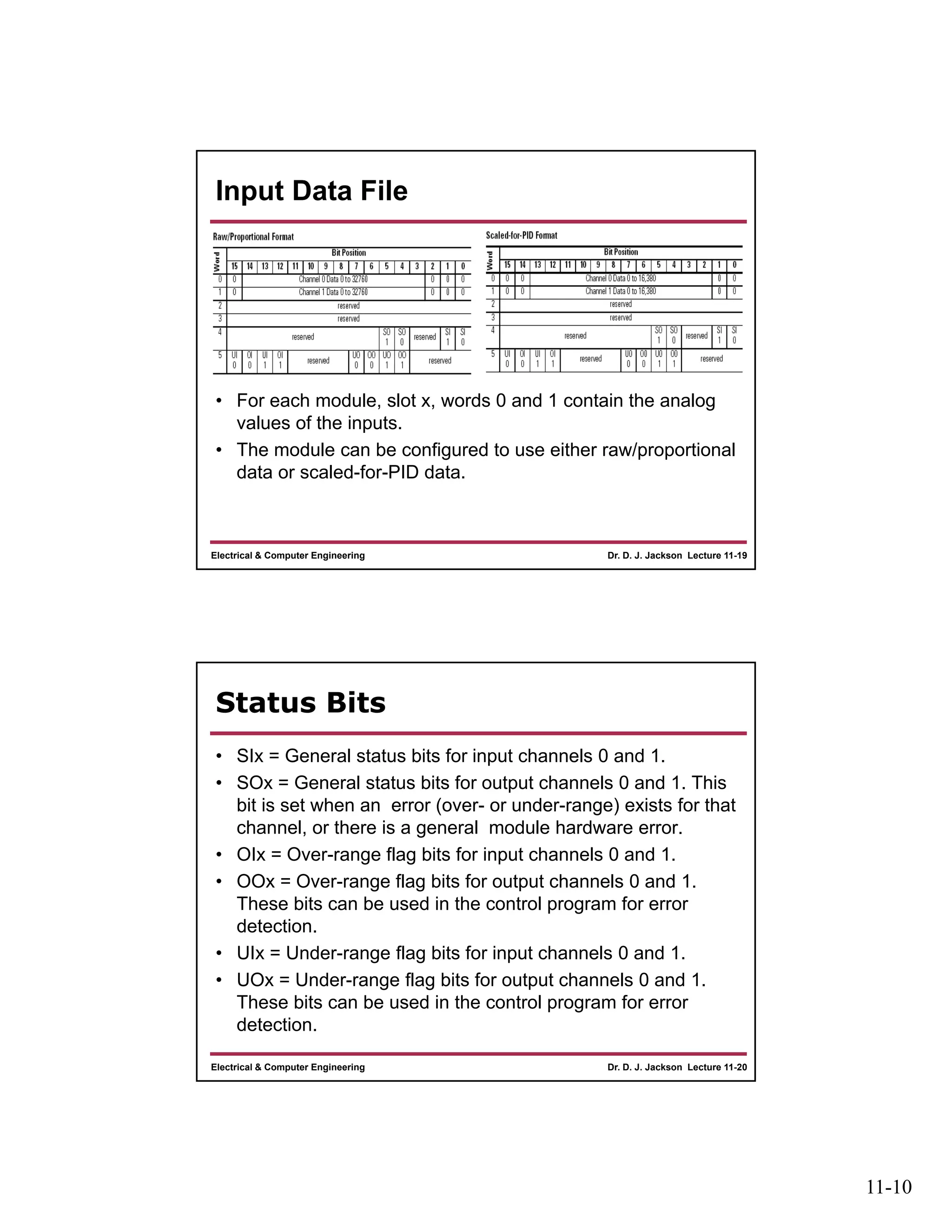
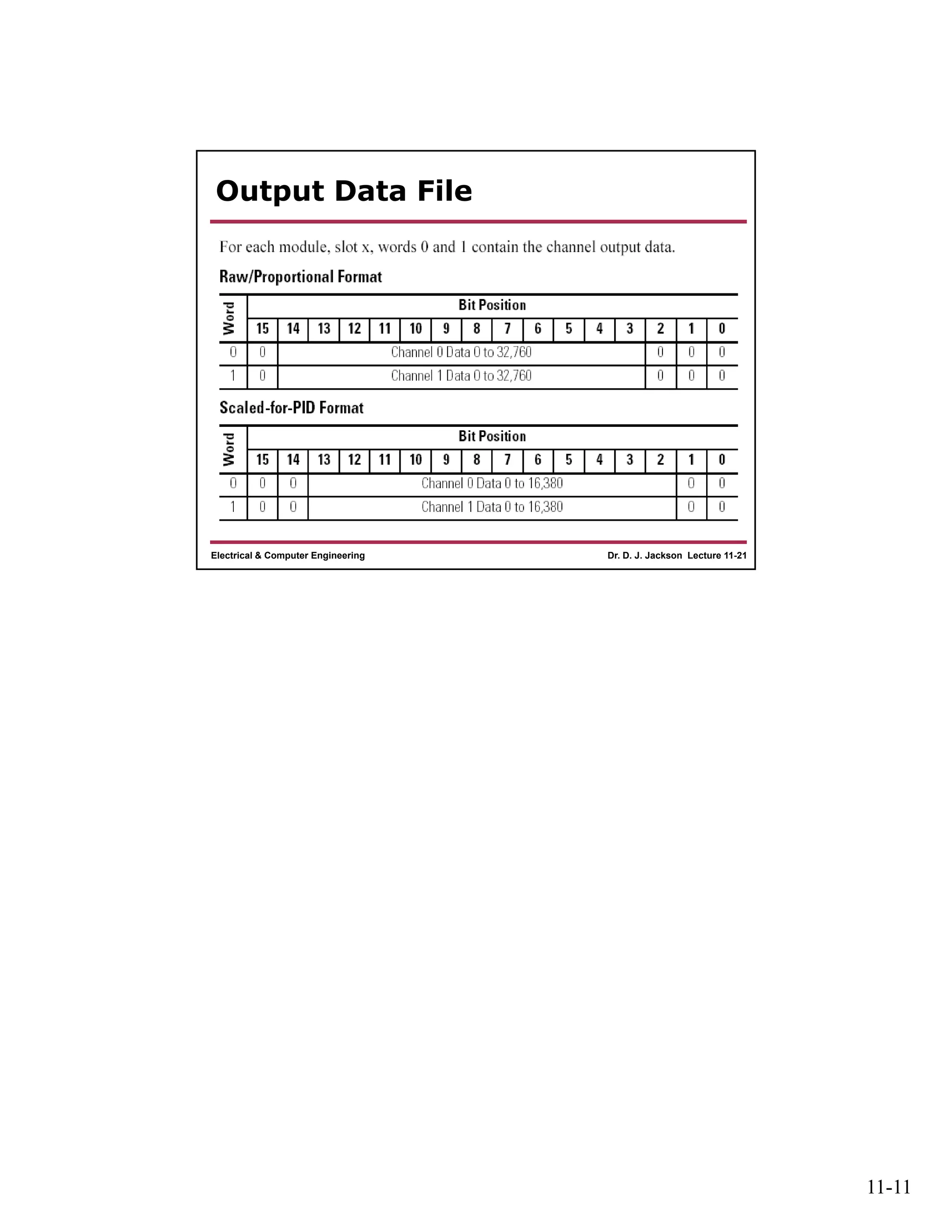
11-1
Dr. D. J. Jackson Lecture 11-1Electrical & Computer Engineering
Programmable Logic
Controllers
PLC I/O Module Types and PLC
Trainer Configuration
Dr. D. J. Jackson Lecture 11-2Electrical & Computer Engineering
Basic Module Types
• Digital (discrete) output modules
– Optical isolation provided
– Relay, transistor or triac based
– Transistor-based outputs may be
• Current sourcing or
• Current sinking
• Digital (discrete) input modules
– Optical isolation provided
– Diode based
• Current sinking, sourcing or both depending on device
11-2
Dr. D. J. Jackson Lecture 11-3Electrical & Computer Engineering
Relay Output Module
CPU
Power
Actuator
+/- -/+
common
0
7
6
OUT6
Dr. D. J. Jackson Lecture 11-4Electrical & Computer Engineering
Relay Output Module
• Coil actuated switch closing
• AC or DC switching
– Relay determines current carrying capacity
• More expensive relay I/O modules may have
two external contacts per relay
– Separate actuator and power supply can be
connected to each relay-controlled circuit
– Most flexible in terms of power types (AC or DC)
and connections
• Less expensive relay I/O module
– Common contact for a group (or all) outputs
11-3
Dr. D. J. Jackson Lecture 11-5Electrical & Computer Engineering
Current Sourcing Transistor
Output Module
CPU
Power
Actuator
+ -
Positive
common
0
7
6
OUT6
B
E
C
Current 
Dr. D. J. Jackson Lecture 11-6Electrical & Computer Engineering
Current Sinking Transistor
Output Module
CPU
Power
Actuator
- +
Negative
common
0
7
6
OUT6
B
E
C
 Current
11-4
Dr. D. J. Jackson Lecture 11-7Electrical & Computer Engineering
Transistor Output Modules
• PNP transistors used in current sourcing
output modules
• Positive common may be shared across all
(or groups of) inputs
• NPN transistors used in current sinking
output modules
• Negative common may be shared across all
(or groups of) inputs
• BE AWARE OF THE OUTPUT TYPE
– Sourcing vs. Sinking
• Power supply connections are different between the types
Dr. D. J. Jackson Lecture 11-8Electrical & Computer Engineering
Current Sourcing/Sinking TRIAC
Output Module
CPU
Power
Actuator
+/- -/+
common
0
7
6
OUT6
TRIAC allows current flow in either direction if triac’s gate contact
is energized. Power supply polarity is not important. AC is allowed.
More expensive than transistor-based modules.
11-5
Dr. D. J. Jackson Lecture 11-9Electrical & Computer Engineering
Current Sinking Optoisolated
Input Module
CPU
Power
- +
common
0
7
6
IN6
 Current
sensor
+5V
Dr. D. J. Jackson Lecture 11-10Electrical & Computer Engineering
Current Sourcing Optoisolated
Input Module
CPU
Power
+ -
common
0
7
6
IN6
Current 
sensor
+5V
11-6
Dr. D. J. Jackson Lecture 11-11Electrical & Computer Engineering
Sinking/Sourcing Optoisolated
Input Module
CPU
Power
+/- -/+
common
0
7
6 IN6
sensor
+5V
Dr. D. J. Jackson Lecture 11-12Electrical & Computer Engineering
Micrologix 1100 controller
11-7
Dr. D. J. Jackson Lecture 11-13Electrical & Computer Engineering
Controller Wiring
• 1763-L16BWA
– 120V AC input power
– (6) 24 Vdc inputs
– (4) high-speed 24 Vdc inputs
– (6) relay outputs
– (2) voltage inputs 0-10Vdc (Not used on the trainer)
Dr. D. J. Jackson Lecture 11-14Electrical & Computer Engineering
Trainer Wiring
(sink/source input module)
• All inputs (I/0-I/9)have similar wiring.
• I/0-I/2 have a normally open momentary pushbutton
• I/3-I/5 have a normally closed momentary
pushbutton
• I/6-I/9 have toggle switches attached to the input
11-8
Dr. D. J. Jackson Lecture 11-15Electrical & Computer Engineering
Trainer Wiring
(relay output module)
AC power
24Vdc
power supply- +
All outputs have similar wiring.
Dr. D. J. Jackson Lecture 11-16Electrical & Computer Engineering
MicroLogix™ Analog Input/Output
Module (1762-IF2OF2)
• 1a upper panel mounting tab
• 1b lower panel mounting tab
• 2 power diagnostic LED
• 3 module door with terminal
identification label
• 4 bus connector with male pins
• 5 bus connector cover
• 6 flat ribbon cable with bus
connector (female)
• 7 terminal block
• 8 DIN rail latch
• 9 pull loop
• 10 input type selector switch
11-9
Dr. D. J. Jackson Lecture 11-17Electrical & Computer Engineering
Input Type Selection
• Select the input type, current or voltage, using the switch located on the modules
circuit board and the input type/range selection bits in the Configuration Data
File.
• You can access the switch through the ventilation slots on the top of the module.
– Switch 1 controls channel 0;
– switch 2 controls channel 1.
• The factory default setting for both switch 1 and switch 2 is Current. Switch
positions are shown below.
Dr. D. J. Jackson Lecture 11-18Electrical & Computer Engineering
Output Type Selection
• The output type selection, current or voltage, is made by
wiring to the appropriate terminals, Iout or Vout, and by the
type/range selection bits in the Configuration Data File.
11-10
Dr. D. J. Jackson Lecture 11-19Electrical & Computer Engineering
Input Data File
• For each module, slot x, words 0 and 1 contain the analog
values of the inputs.
• The module can be configured to use either raw/proportional
data or scaled-for-PID data.
Dr. D. J. Jackson Lecture 11-20Electrical & Computer Engineering
Status Bits
• SIx = General status bits for input channels 0 and 1.
• SOx = General status bits for output channels 0 and 1. This
bit is set when an error (over- or under-range) exists for that
channel, or there is a general module hardware error.
• OIx = Over-range flag bits for input channels 0 and 1.
• OOx = Over-range flag bits for output channels 0 and 1.
These bits can be used in the control program for error
detection.
• UIx = Under-range flag bits for input channels 0 and 1.
• UOx = Under-range flag bits for output channels 0 and 1.
These bits can be used in the control program for error
detection.
11-11
Dr. D. J. Jackson Lecture 11-21Electrical & Computer Engineering
Output Data File

Lect11

  • 1.
    11-1 Dr. D. J.Jackson Lecture 11-1Electrical & Computer Engineering Programmable Logic Controllers PLC I/O Module Types and PLC Trainer Configuration Dr. D. J. Jackson Lecture 11-2Electrical & Computer Engineering Basic Module Types • Digital (discrete) output modules – Optical isolation provided – Relay, transistor or triac based – Transistor-based outputs may be • Current sourcing or • Current sinking • Digital (discrete) input modules – Optical isolation provided – Diode based • Current sinking, sourcing or both depending on device
  • 2.
    11-2 Dr. D. J.Jackson Lecture 11-3Electrical & Computer Engineering Relay Output Module CPU Power Actuator +/- -/+ common 0 7 6 OUT6 Dr. D. J. Jackson Lecture 11-4Electrical & Computer Engineering Relay Output Module • Coil actuated switch closing • AC or DC switching – Relay determines current carrying capacity • More expensive relay I/O modules may have two external contacts per relay – Separate actuator and power supply can be connected to each relay-controlled circuit – Most flexible in terms of power types (AC or DC) and connections • Less expensive relay I/O module – Common contact for a group (or all) outputs
  • 3.
    11-3 Dr. D. J.Jackson Lecture 11-5Electrical & Computer Engineering Current Sourcing Transistor Output Module CPU Power Actuator + - Positive common 0 7 6 OUT6 B E C Current  Dr. D. J. Jackson Lecture 11-6Electrical & Computer Engineering Current Sinking Transistor Output Module CPU Power Actuator - + Negative common 0 7 6 OUT6 B E C  Current
  • 4.
    11-4 Dr. D. J.Jackson Lecture 11-7Electrical & Computer Engineering Transistor Output Modules • PNP transistors used in current sourcing output modules • Positive common may be shared across all (or groups of) inputs • NPN transistors used in current sinking output modules • Negative common may be shared across all (or groups of) inputs • BE AWARE OF THE OUTPUT TYPE – Sourcing vs. Sinking • Power supply connections are different between the types Dr. D. J. Jackson Lecture 11-8Electrical & Computer Engineering Current Sourcing/Sinking TRIAC Output Module CPU Power Actuator +/- -/+ common 0 7 6 OUT6 TRIAC allows current flow in either direction if triac’s gate contact is energized. Power supply polarity is not important. AC is allowed. More expensive than transistor-based modules.
  • 5.
    11-5 Dr. D. J.Jackson Lecture 11-9Electrical & Computer Engineering Current Sinking Optoisolated Input Module CPU Power - + common 0 7 6 IN6  Current sensor +5V Dr. D. J. Jackson Lecture 11-10Electrical & Computer Engineering Current Sourcing Optoisolated Input Module CPU Power + - common 0 7 6 IN6 Current  sensor +5V
  • 6.
    11-6 Dr. D. J.Jackson Lecture 11-11Electrical & Computer Engineering Sinking/Sourcing Optoisolated Input Module CPU Power +/- -/+ common 0 7 6 IN6 sensor +5V Dr. D. J. Jackson Lecture 11-12Electrical & Computer Engineering Micrologix 1100 controller
  • 7.
    11-7 Dr. D. J.Jackson Lecture 11-13Electrical & Computer Engineering Controller Wiring • 1763-L16BWA – 120V AC input power – (6) 24 Vdc inputs – (4) high-speed 24 Vdc inputs – (6) relay outputs – (2) voltage inputs 0-10Vdc (Not used on the trainer) Dr. D. J. Jackson Lecture 11-14Electrical & Computer Engineering Trainer Wiring (sink/source input module) • All inputs (I/0-I/9)have similar wiring. • I/0-I/2 have a normally open momentary pushbutton • I/3-I/5 have a normally closed momentary pushbutton • I/6-I/9 have toggle switches attached to the input
  • 8.
    11-8 Dr. D. J.Jackson Lecture 11-15Electrical & Computer Engineering Trainer Wiring (relay output module) AC power 24Vdc power supply- + All outputs have similar wiring. Dr. D. J. Jackson Lecture 11-16Electrical & Computer Engineering MicroLogix™ Analog Input/Output Module (1762-IF2OF2) • 1a upper panel mounting tab • 1b lower panel mounting tab • 2 power diagnostic LED • 3 module door with terminal identification label • 4 bus connector with male pins • 5 bus connector cover • 6 flat ribbon cable with bus connector (female) • 7 terminal block • 8 DIN rail latch • 9 pull loop • 10 input type selector switch
  • 9.
    11-9 Dr. D. J.Jackson Lecture 11-17Electrical & Computer Engineering Input Type Selection • Select the input type, current or voltage, using the switch located on the modules circuit board and the input type/range selection bits in the Configuration Data File. • You can access the switch through the ventilation slots on the top of the module. – Switch 1 controls channel 0; – switch 2 controls channel 1. • The factory default setting for both switch 1 and switch 2 is Current. Switch positions are shown below. Dr. D. J. Jackson Lecture 11-18Electrical & Computer Engineering Output Type Selection • The output type selection, current or voltage, is made by wiring to the appropriate terminals, Iout or Vout, and by the type/range selection bits in the Configuration Data File.
  • 10.
    11-10 Dr. D. J.Jackson Lecture 11-19Electrical & Computer Engineering Input Data File • For each module, slot x, words 0 and 1 contain the analog values of the inputs. • The module can be configured to use either raw/proportional data or scaled-for-PID data. Dr. D. J. Jackson Lecture 11-20Electrical & Computer Engineering Status Bits • SIx = General status bits for input channels 0 and 1. • SOx = General status bits for output channels 0 and 1. This bit is set when an error (over- or under-range) exists for that channel, or there is a general module hardware error. • OIx = Over-range flag bits for input channels 0 and 1. • OOx = Over-range flag bits for output channels 0 and 1. These bits can be used in the control program for error detection. • UIx = Under-range flag bits for input channels 0 and 1. • UOx = Under-range flag bits for output channels 0 and 1. These bits can be used in the control program for error detection.
  • 11.
    11-11 Dr. D. J.Jackson Lecture 11-21Electrical & Computer Engineering Output Data File