
Recommended
More Related Content
What's hot
What's hot (20)
Similar to New generation numeric protection relays
Similar to New generation numeric protection relays (20)
More from ashwini reliserv
More from ashwini reliserv (20)
Recently uploaded
Recently uploaded (20)
New generation numeric protection relays
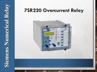
- 2. Description • The 7SR210 and 7SR220 are a new generation of nondirectional and directional overcurrent protection relays, built on years of numeric relay protection experience with the Argus family of products. • Housed in 4U high, size E6, E8 or E12 cases, these relays provide protection, control, monitoring, instrumentation and metering with integrated input and output logic, data logging & fault reports. • Communication access to relay functionality is via a front USB port for local PC connection or rear electrical RS485 port for remote connection. Additional rear port options are available.
- 3. Function Keys Six or twelve user programmable function keys are available for implementing User logic and scheme control functionality, eliminating the need for expensive panel mounted control switches and associated wiring. Each function key has an associated user programmable tri- color LED (red, green, yellow) allowing for clear indication of the associated function’s state. A slip-in label pocket along-side enables the user to insert his own notation for the function Key LED Identification. Each Function Key can be mapped directly to any of the built-in Command functions or to the User Logic equations
- 4. Function Overview • 37 Undercurrent • 46BC Broken Conductor / Load Unbalance • 46NPS Negative Phase Sequence Overcurrent • 49 Thermal Overload 50 Instantaneous Overcurrent • 50G/N Instantaneous Earth Fault • 50BF Circuit Breaker Fail • 50AFD Arc Flash Detector • 51 Time Delayed Overcurrent • 51G/N Time Delayed Measured Earth Fault /SEF • 60CTS-I CT Supervision • 64H High Impedance REF • 74TC/CC Trip/Close Circuit Supervision • 81HBL2 2nd Harmonic Block/Inrush Restraint • 51c Cold Load Pickup • 8 Settings Groups • Password Protection – 2 levels • User Programmable Logic
- 5. Data Communications • Standard Communications Ports Communication access to relay functionality is via a front USB port for local PC connection or rear electrical RS485 port for remote connection • Optional Communications Ports 2 Rear ST fibre optic ports (2 x Tx/Rx) + IRIG-B port 1 Rear RS485 + IRIG-B port 1 Rear RS232 + IRIG-B port 2 Electrical Ethernet 2 Optical Ethernet • Protocols IEC60870-5-103, Modbus RTU and optional DNP 3.0 protocols – User selectable with programmable data points IEC61850 over Ethernet – optional Ethernet Redundancy: RSTP, HSR & PRP – standard on ethernet equipped models
- 7. Optional Functionality 79 Auto-Reclose This function provides independent Phase fault and Earth Fault/Sensitive Earth fault sequences of up to 5 Trips i.e. 4 Reclose attempts before Lockout. Auto-Reclose sequence can be user set to be initiated from internal protection operation or via Binary Input from an external Protection. The user can set each trip in the sequence to be either instantaneous (Fast) or delayed. Independent times can be set by the user for Reclose (Dead) time and Reclaim time. 25 Check Sync The check synchronizing function is used to check that the voltage conditions, measured by the voltage transformers on either side of the open circuit breaker, indicate that it is safe to close without risk of damage to the circuit breaker or disturbance to the system.
- 8. Additional Functionality 27/59 Under/Over Voltage Each element has settings for pickup level, drop-off level and Definite Time Lag (DTL) delays. Operates if voltage ‘exceeds’ setting for duration of delay. 47 Negative Phase Sequence Overvoltage Each element has settings for pickup level and Definite Time Lag (DTL) delays. Operates if NPS Voltage exceeds setting for duration of delay. 51V Voltage Controlled OverCurrent Element has settings for UnderVoltage pickup level and operates if voltage falls below setting. 59N Neutral Overvoltage Two elements, one DTL and one IDMTL, have user settings for pickup level and delays. 60CTS CT Supervision The CT Supervision considers the presence of negative phase sequence current, without an equivalent level of negative phase sequence voltage, for a user set time as a CT failure.
- 9. Monitoring Functions Standard Monitoring – 7SR220 o Direction o Frequency o Primary line and phase voltages o Secondary voltages o Apparent power and power factor o Real and reactive power o W Hr forward and reverse o VAr Hr forward and reverse o Historical demand record o Positive phase sequence (PPS) Voltage o Negative phase sequence (NPS) Voltage o Zero phase sequence (ZPS) Voltage
- 10. Reydisp Evolution Reydisp Evolution is common to the entire range of Reyrolle numeric products. It provides a means for the user to apply settings, interrogate settings and also to retrieve events & disturbance waveforms from the relay.
- 11. Data Acquisition - Via Communication Interface • Sequence of event records Up to 5000 events are stored and time tagged to 1 ms resolution. These can be viewed on the fascia LCD. • Fault Records Up to 100 fault records are stored and can be downloaded from the relay through the communication interface, with time & date of trip, measured quantities and type of fault. • Waveform recorder The waveform recorder stores analogue data for all poles and the states of protection functions, binary inputs, LEDs and binary outputs with user settable pre & post trigger data. • Demand Monitoring A record of demand is available. The demand minimum, maximum and average values for currents, frequency and if applicable, voltages and real, reactive and apparent power and power factor, over a user selectable period of time, is displayed and available via data communications.
- 14. Technical Data - Inputs and Outputs
- 15. Mob No: Mr. Piyush Rathi- +91-9819614841 Website: www.reliservsolution.com Email-ID: piyush@reliserv.in sales1@reliserv.in Address: Office No: 9, Space Heights, Plot No. 53/54 , Sector 34, Kamothe,Navi Mumbai- 410209 Contact us