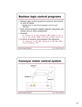
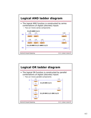
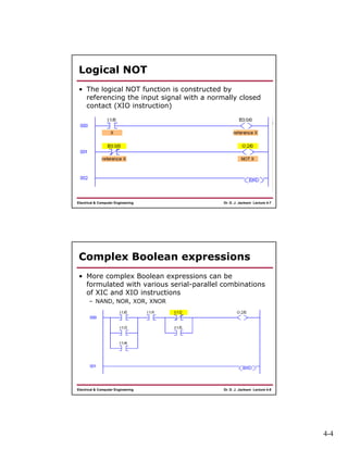
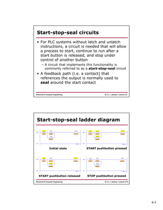
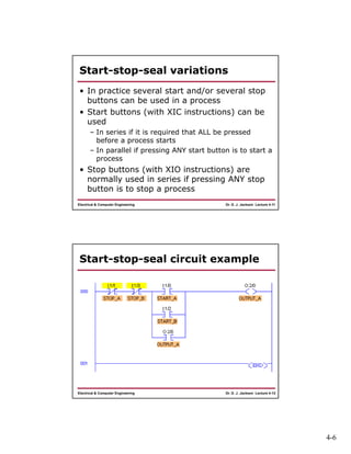
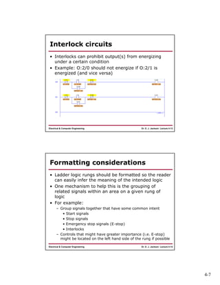
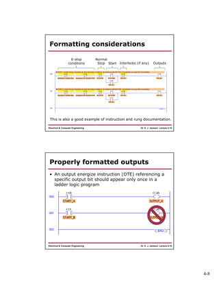
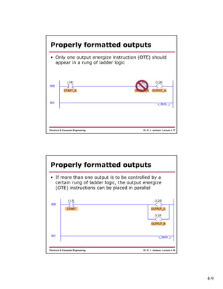
4-1
Dr. D. J. Jackson Lecture 4-1Electrical & Computer Engineering
Programmable Logic
Controllers
Basic Ladder Logic Programming
Dr. D. J. Jackson Lecture 4-2Electrical & Computer Engineering
Outline
• Boolean statements and ladder logic
equivalents
– Logical AND
– Logical OR
– Logical NOT
• Commonly used ladder logic sequences
– Start-stop-seal circuits
– Basic interlocks
• Properly formatted outputs
4-2
Dr. D. J. Jackson Lecture 4-3Electrical & Computer Engineering
Boolean logic control programs
• Boolean logic control programs examine and control
on and off states
– Boolean here is used interchangeably with the word
“discrete”
• Each control program (ladder diagram sequence) can
contain one or more conditionals
• Example
– If (a part is on the conveyor) AND (there is not a
box in the chute) THEN (turn the conveyor motor on)
• In terms of sensors and actuators this becomes
– If (sensor_A is ON) AND (sensor_B is NOT ON) THEN
(turn actuator_C ON)
Dr. D. J. Jackson Lecture 4-4Electrical & Computer Engineering
Conveyor motor control system
sensor_A
sensor_B
actuator_C
4-3
Dr. D. J. Jackson Lecture 4-5Electrical & Computer Engineering
Logical AND ladder diagram
• The logical AND function is constructed by series
combinations of digital (discrete) inputs
– Two (or more) series components
I:1/0 AND I:1/1
I:1/0 AND I:1/1 AND I:1/2
Dr. D. J. Jackson Lecture 4-6Electrical & Computer Engineering
Logical OR ladder diagram
• The logical OR function is constructed by parallel
combinations of digital (discrete) inputs
– Two (or more) parallel components
I:1/0 OR I:1/1
I:1/0 OR I:1/1 OR I:1/2
4-4
Dr. D. J. Jackson Lecture 4-7Electrical & Computer Engineering
Logical NOT
• The logical NOT function is constructed by
referencing the input signal with a normally closed
contact (XIO instruction)
Dr. D. J. Jackson Lecture 4-8Electrical & Computer Engineering
Complex Boolean expressions
• More complex Boolean expressions can be
formulated with various serial-parallel combinations
of XIC and XIO instructions
– NAND, NOR, XOR, XNOR
4-5
Dr. D. J. Jackson Lecture 4-9Electrical & Computer Engineering
Start-stop-seal circuits
• For PLC systems without latch and unlatch
instructions, a circuit is needed that will allow
a process to start, continue to run after a
start button is released, and stop under
control of another button
– A circuit that implements this functionality is
commonly referred to as a start-stop-seal circuit
• A feedback path (i.e. a contact) that
references the output is normally used to
seal around the start contact
Dr. D. J. Jackson Lecture 4-10Electrical & Computer Engineering
Start-stop-seal ladder diagram
Initial state START pushbutton pressed
START pushbutton released STOP pushbutton pressed
4-6
Dr. D. J. Jackson Lecture 4-11Electrical & Computer Engineering
Start-stop-seal variations
• In practice several start and/or several stop
buttons can be used in a process
• Start buttons (with XIC instructions) can be
used
– In series if it is required that ALL be pressed
before a process starts
– In parallel if pressing ANY start button is to start a
process
• Stop buttons (with XIO instructions) are
normally used in series if pressing ANY stop
button is to stop a process
Dr. D. J. Jackson Lecture 4-12Electrical & Computer Engineering
Start-stop-seal circuit example
4-7
Dr. D. J. Jackson Lecture 4-13Electrical & Computer Engineering
Interlock circuits
• Interlocks can prohibit output(s) from energizing
under a certain condition
• Example: O:2/0 should not energize if O:2/1 is
energized (and vice versa)
Dr. D. J. Jackson Lecture 4-14Electrical & Computer Engineering
Formatting considerations
• Ladder logic rungs should be formatted so the reader
can easily infer the meaning of the intended logic
• One mechanism to help this is the grouping of
related signals within an area on a given rung of
logic
• For example:
– Group signals together that have some common intent
• Start signals
• Stop signals
• Emergency stop signals (E-stop)
• Interlocks
– Controls that might have greater importance (i.e. E-stop)
might be located on the left hand side of the rung if possible
4-8
Dr. D. J. Jackson Lecture 4-15Electrical & Computer Engineering
Formatting considerations
E-stop
conditions
Normal
Stop Start Interlocks (if any) Outputs
This is also a good example of instruction and rung documentation.
Dr. D. J. Jackson Lecture 4-16Electrical & Computer Engineering
Properly formatted outputs
• An output energize instruction (OTE) referencing a
specific output bit should appear only once in a
ladder logic program
4-9
Dr. D. J. Jackson Lecture 4-17Electrical & Computer Engineering
Properly formatted outputs
• Only one output energize instruction (OTE) should
appear in a rung of ladder logic
Dr. D. J. Jackson Lecture 4-18Electrical & Computer Engineering
Properly formatted outputs
• If more than one output is to be controlled by a
certain rung of ladder logic, the output energize
(OTE) instructions can be placed in parallel

Lect04

  • 1.
    4-1 Dr. D. J.Jackson Lecture 4-1Electrical & Computer Engineering Programmable Logic Controllers Basic Ladder Logic Programming Dr. D. J. Jackson Lecture 4-2Electrical & Computer Engineering Outline • Boolean statements and ladder logic equivalents – Logical AND – Logical OR – Logical NOT • Commonly used ladder logic sequences – Start-stop-seal circuits – Basic interlocks • Properly formatted outputs
  • 2.
    4-2 Dr. D. J.Jackson Lecture 4-3Electrical & Computer Engineering Boolean logic control programs • Boolean logic control programs examine and control on and off states – Boolean here is used interchangeably with the word “discrete” • Each control program (ladder diagram sequence) can contain one or more conditionals • Example – If (a part is on the conveyor) AND (there is not a box in the chute) THEN (turn the conveyor motor on) • In terms of sensors and actuators this becomes – If (sensor_A is ON) AND (sensor_B is NOT ON) THEN (turn actuator_C ON) Dr. D. J. Jackson Lecture 4-4Electrical & Computer Engineering Conveyor motor control system sensor_A sensor_B actuator_C
  • 3.
    4-3 Dr. D. J.Jackson Lecture 4-5Electrical & Computer Engineering Logical AND ladder diagram • The logical AND function is constructed by series combinations of digital (discrete) inputs – Two (or more) series components I:1/0 AND I:1/1 I:1/0 AND I:1/1 AND I:1/2 Dr. D. J. Jackson Lecture 4-6Electrical & Computer Engineering Logical OR ladder diagram • The logical OR function is constructed by parallel combinations of digital (discrete) inputs – Two (or more) parallel components I:1/0 OR I:1/1 I:1/0 OR I:1/1 OR I:1/2
  • 4.
    4-4 Dr. D. J.Jackson Lecture 4-7Electrical & Computer Engineering Logical NOT • The logical NOT function is constructed by referencing the input signal with a normally closed contact (XIO instruction) Dr. D. J. Jackson Lecture 4-8Electrical & Computer Engineering Complex Boolean expressions • More complex Boolean expressions can be formulated with various serial-parallel combinations of XIC and XIO instructions – NAND, NOR, XOR, XNOR
  • 5.
    4-5 Dr. D. J.Jackson Lecture 4-9Electrical & Computer Engineering Start-stop-seal circuits • For PLC systems without latch and unlatch instructions, a circuit is needed that will allow a process to start, continue to run after a start button is released, and stop under control of another button – A circuit that implements this functionality is commonly referred to as a start-stop-seal circuit • A feedback path (i.e. a contact) that references the output is normally used to seal around the start contact Dr. D. J. Jackson Lecture 4-10Electrical & Computer Engineering Start-stop-seal ladder diagram Initial state START pushbutton pressed START pushbutton released STOP pushbutton pressed
  • 6.
    4-6 Dr. D. J.Jackson Lecture 4-11Electrical & Computer Engineering Start-stop-seal variations • In practice several start and/or several stop buttons can be used in a process • Start buttons (with XIC instructions) can be used – In series if it is required that ALL be pressed before a process starts – In parallel if pressing ANY start button is to start a process • Stop buttons (with XIO instructions) are normally used in series if pressing ANY stop button is to stop a process Dr. D. J. Jackson Lecture 4-12Electrical & Computer Engineering Start-stop-seal circuit example
  • 7.
    4-7 Dr. D. J.Jackson Lecture 4-13Electrical & Computer Engineering Interlock circuits • Interlocks can prohibit output(s) from energizing under a certain condition • Example: O:2/0 should not energize if O:2/1 is energized (and vice versa) Dr. D. J. Jackson Lecture 4-14Electrical & Computer Engineering Formatting considerations • Ladder logic rungs should be formatted so the reader can easily infer the meaning of the intended logic • One mechanism to help this is the grouping of related signals within an area on a given rung of logic • For example: – Group signals together that have some common intent • Start signals • Stop signals • Emergency stop signals (E-stop) • Interlocks – Controls that might have greater importance (i.e. E-stop) might be located on the left hand side of the rung if possible
  • 8.
    4-8 Dr. D. J.Jackson Lecture 4-15Electrical & Computer Engineering Formatting considerations E-stop conditions Normal Stop Start Interlocks (if any) Outputs This is also a good example of instruction and rung documentation. Dr. D. J. Jackson Lecture 4-16Electrical & Computer Engineering Properly formatted outputs • An output energize instruction (OTE) referencing a specific output bit should appear only once in a ladder logic program
  • 9.
    4-9 Dr. D. J.Jackson Lecture 4-17Electrical & Computer Engineering Properly formatted outputs • Only one output energize instruction (OTE) should appear in a rung of ladder logic Dr. D. J. Jackson Lecture 4-18Electrical & Computer Engineering Properly formatted outputs • If more than one output is to be controlled by a certain rung of ladder logic, the output energize (OTE) instructions can be placed in parallel