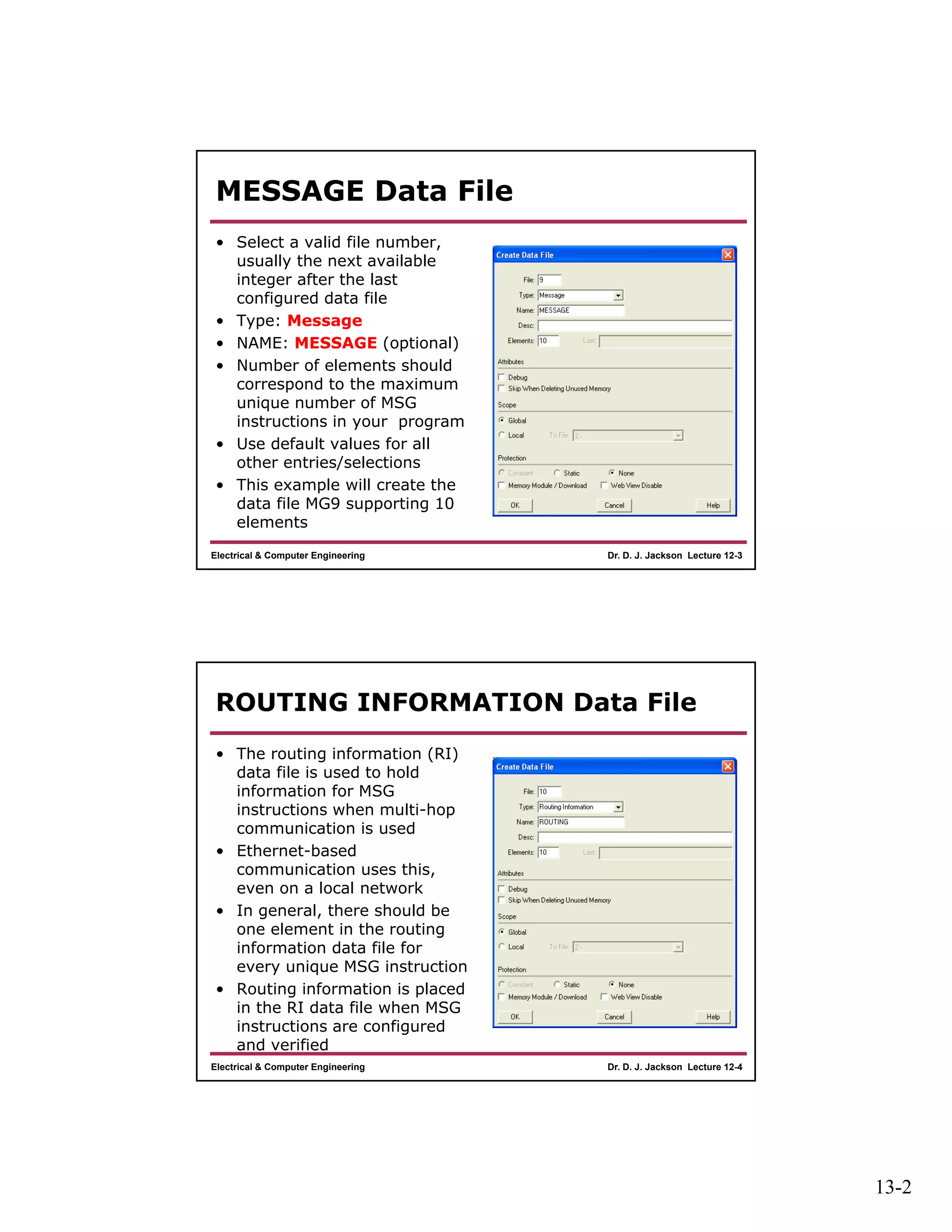
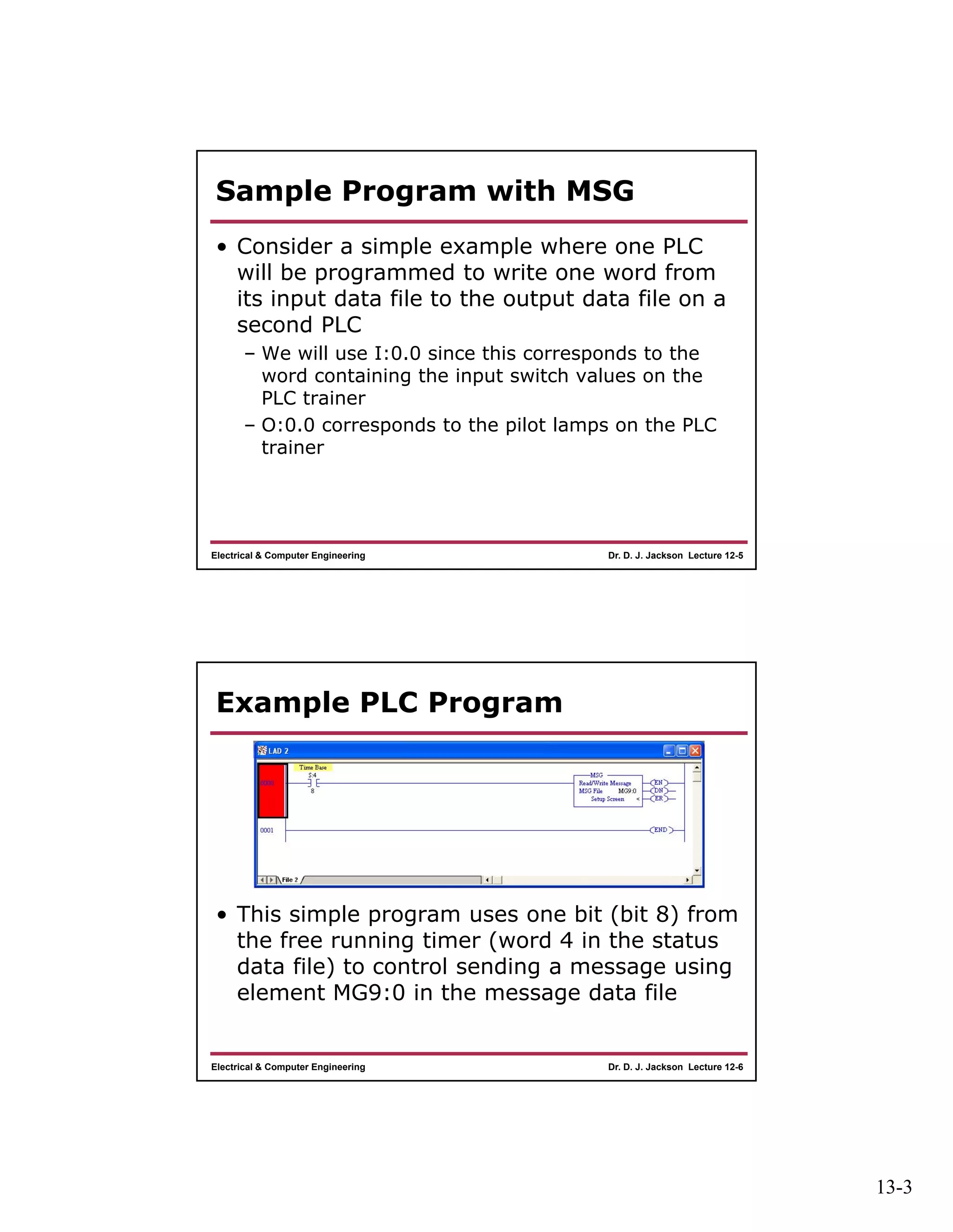
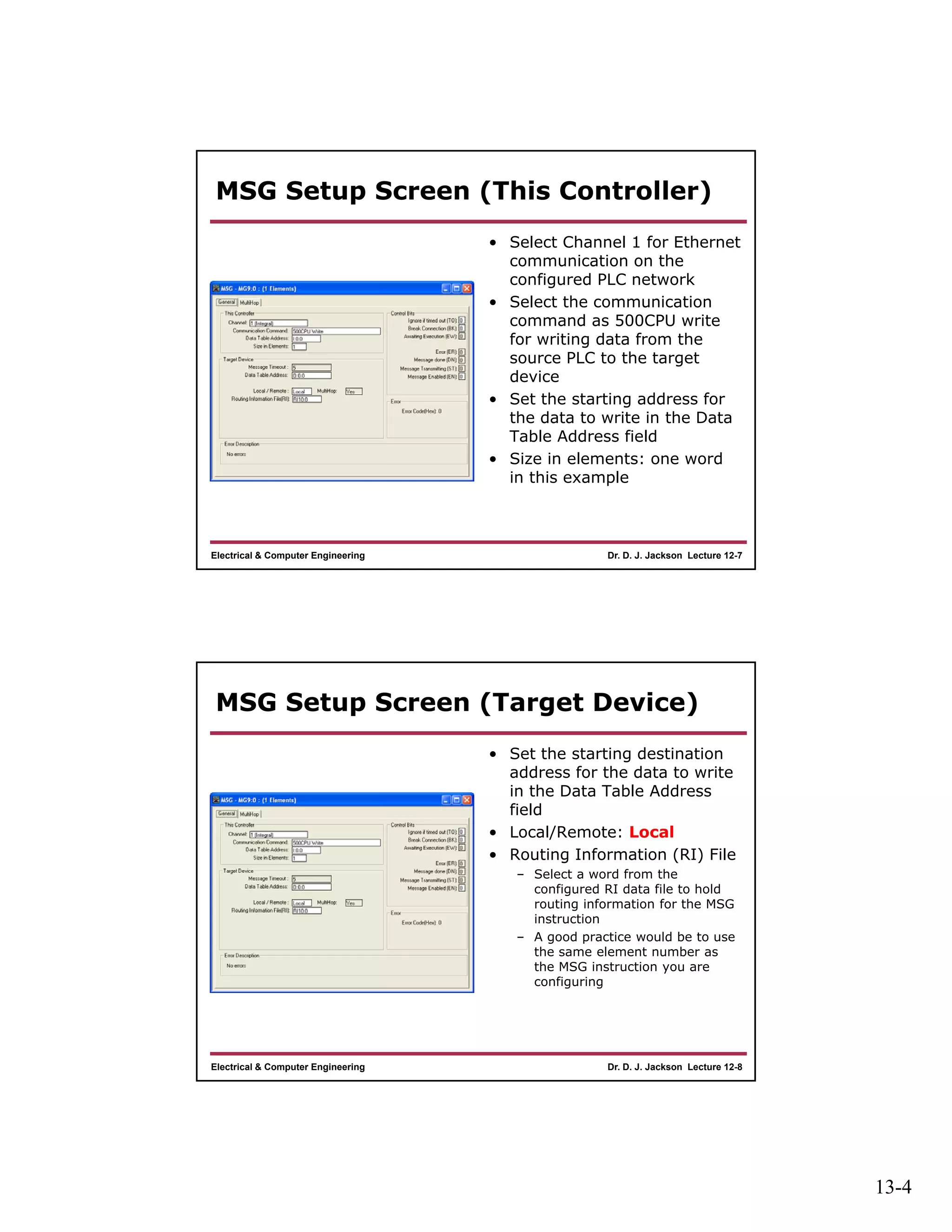
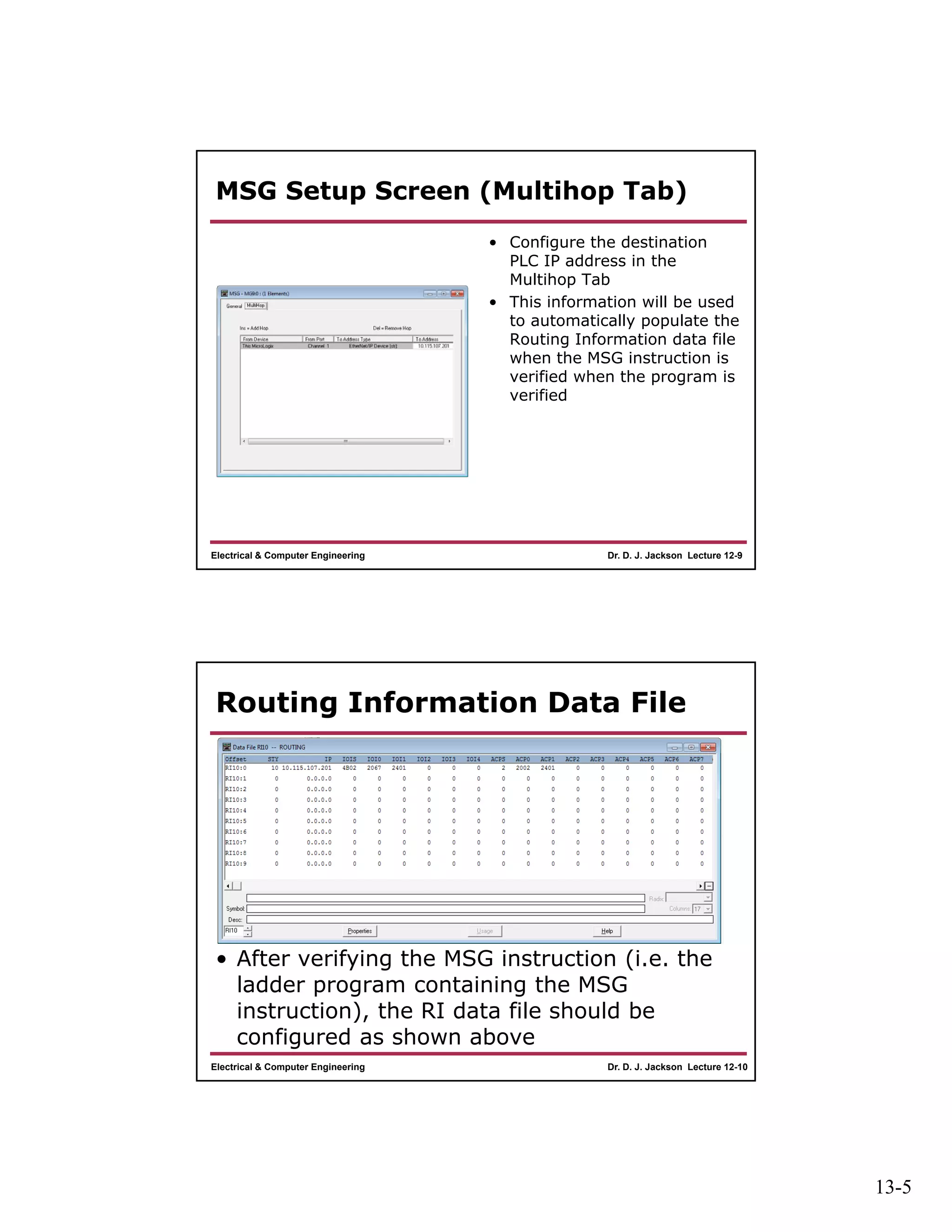
13-1
Dr. D. J. Jackson Lecture 12-1Electrical & Computer Engineering
Programmable Logic
Controllers
Ethernet-Based Communication
Setup and MSG Instruction Use
Dr. D. J. Jackson Lecture 12-2Electrical & Computer Engineering
Communications Setup
• Assuming an RSLogix ladder logic program is
properly setup to use one of the PLCs on the
network, two additional data files need to be
created to support use of the MSG instruction
– A MESSAGE data file
• Will hold all information for configured MSG instructions
– A ROUTING INFORMATION data file
• Will hold routing information from configured MSG
instructions
13-2
Dr. D. J. Jackson Lecture 12-3Electrical & Computer Engineering
MESSAGE Data File
• Select a valid file number,
usually the next available
integer after the last
configured data file
• Type: Message
• NAME: MESSAGE (optional)
• Number of elements should
correspond to the maximum
unique number of MSG
instructions in your program
• Use default values for all
other entries/selections
• This example will create the
data file MG9 supporting 10
elements
Dr. D. J. Jackson Lecture 12-4Electrical & Computer Engineering
ROUTING INFORMATION Data File
• The routing information (RI)
data file is used to hold
information for MSG
instructions when multi-hop
communication is used
• Ethernet-based
communication uses this,
even on a local network
• In general, there should be
one element in the routing
information data file for
every unique MSG instruction
• Routing information is placed
in the RI data file when MSG
instructions are configured
and verified
13-3
Dr. D. J. Jackson Lecture 12-5Electrical & Computer Engineering
Sample Program with MSG
• Consider a simple example where one PLC
will be programmed to write one word from
its input data file to the output data file on a
second PLC
– We will use I:0.0 since this corresponds to the
word containing the input switch values on the
PLC trainer
– O:0.0 corresponds to the pilot lamps on the PLC
trainer
Dr. D. J. Jackson Lecture 12-6Electrical & Computer Engineering
Example PLC Program
• This simple program uses one bit (bit 8) from
the free running timer (word 4 in the status
data file) to control sending a message using
element MG9:0 in the message data file
13-4
Dr. D. J. Jackson Lecture 12-7Electrical & Computer Engineering
MSG Setup Screen (This Controller)
• Select Channel 1 for Ethernet
communication on the
configured PLC network
• Select the communication
command as 500CPU write
for writing data from the
source PLC to the target
device
• Set the starting address for
the data to write in the Data
Table Address field
• Size in elements: one word
in this example
Dr. D. J. Jackson Lecture 12-8Electrical & Computer Engineering
MSG Setup Screen (Target Device)
• Set the starting destination
address for the data to write
in the Data Table Address
field
• Local/Remote: Local
• Routing Information (RI) File
– Select a word from the
configured RI data file to hold
routing information for the MSG
instruction
– A good practice would be to use
the same element number as
the MSG instruction you are
configuring
13-5
Dr. D. J. Jackson Lecture 12-9Electrical & Computer Engineering
MSG Setup Screen (Multihop Tab)
• Configure the destination
PLC IP address in the
Multihop Tab
• This information will be used
to automatically populate the
Routing Information data file
when the MSG instruction is
verified when the program is
verified
Dr. D. J. Jackson Lecture 12-10Electrical & Computer Engineering
Routing Information Data File
• After verifying the MSG instruction (i.e. the
ladder program containing the MSG
instruction), the RI data file should be
configured as shown above

Lect12

  • 1.
    13-1 Dr. D. J.Jackson Lecture 12-1Electrical & Computer Engineering Programmable Logic Controllers Ethernet-Based Communication Setup and MSG Instruction Use Dr. D. J. Jackson Lecture 12-2Electrical & Computer Engineering Communications Setup • Assuming an RSLogix ladder logic program is properly setup to use one of the PLCs on the network, two additional data files need to be created to support use of the MSG instruction – A MESSAGE data file • Will hold all information for configured MSG instructions – A ROUTING INFORMATION data file • Will hold routing information from configured MSG instructions
  • 2.
    13-2 Dr. D. J.Jackson Lecture 12-3Electrical & Computer Engineering MESSAGE Data File • Select a valid file number, usually the next available integer after the last configured data file • Type: Message • NAME: MESSAGE (optional) • Number of elements should correspond to the maximum unique number of MSG instructions in your program • Use default values for all other entries/selections • This example will create the data file MG9 supporting 10 elements Dr. D. J. Jackson Lecture 12-4Electrical & Computer Engineering ROUTING INFORMATION Data File • The routing information (RI) data file is used to hold information for MSG instructions when multi-hop communication is used • Ethernet-based communication uses this, even on a local network • In general, there should be one element in the routing information data file for every unique MSG instruction • Routing information is placed in the RI data file when MSG instructions are configured and verified
  • 3.
    13-3 Dr. D. J.Jackson Lecture 12-5Electrical & Computer Engineering Sample Program with MSG • Consider a simple example where one PLC will be programmed to write one word from its input data file to the output data file on a second PLC – We will use I:0.0 since this corresponds to the word containing the input switch values on the PLC trainer – O:0.0 corresponds to the pilot lamps on the PLC trainer Dr. D. J. Jackson Lecture 12-6Electrical & Computer Engineering Example PLC Program • This simple program uses one bit (bit 8) from the free running timer (word 4 in the status data file) to control sending a message using element MG9:0 in the message data file
  • 4.
    13-4 Dr. D. J.Jackson Lecture 12-7Electrical & Computer Engineering MSG Setup Screen (This Controller) • Select Channel 1 for Ethernet communication on the configured PLC network • Select the communication command as 500CPU write for writing data from the source PLC to the target device • Set the starting address for the data to write in the Data Table Address field • Size in elements: one word in this example Dr. D. J. Jackson Lecture 12-8Electrical & Computer Engineering MSG Setup Screen (Target Device) • Set the starting destination address for the data to write in the Data Table Address field • Local/Remote: Local • Routing Information (RI) File – Select a word from the configured RI data file to hold routing information for the MSG instruction – A good practice would be to use the same element number as the MSG instruction you are configuring
  • 5.
    13-5 Dr. D. J.Jackson Lecture 12-9Electrical & Computer Engineering MSG Setup Screen (Multihop Tab) • Configure the destination PLC IP address in the Multihop Tab • This information will be used to automatically populate the Routing Information data file when the MSG instruction is verified when the program is verified Dr. D. J. Jackson Lecture 12-10Electrical & Computer Engineering Routing Information Data File • After verifying the MSG instruction (i.e. the ladder program containing the MSG instruction), the RI data file should be configured as shown above