This document provides an overview of the key steps for installing and connecting a photovoltaic (PV) system, including:
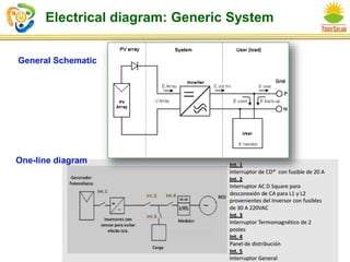
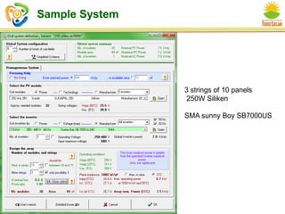
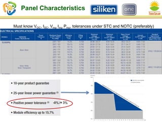
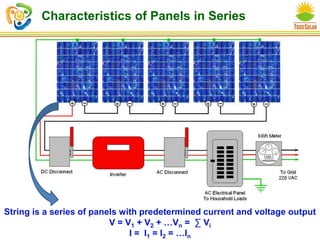
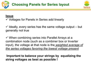
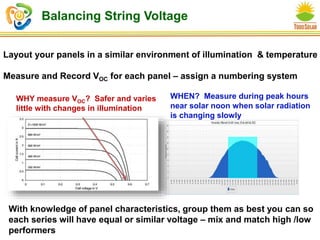
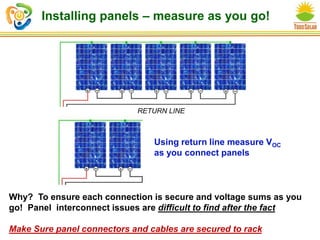
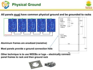
- Choosing and connecting solar panels in series, ensuring proper voltage matching and grounding.
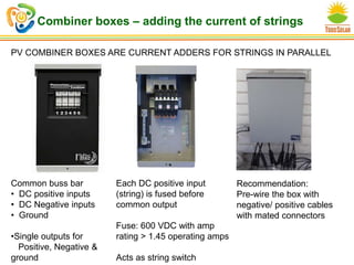
- Using string combiners to combine series connections into parallel arrays and meet input requirements for inverters.
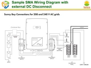
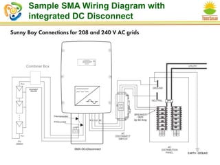
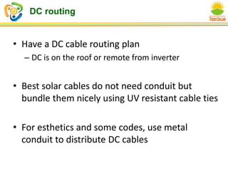
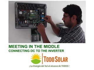
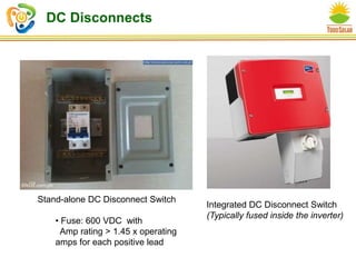
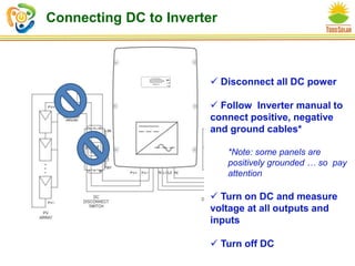
- Connecting the DC side to inverters, including DC disconnects, fusing, and voltage measurements.
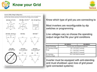
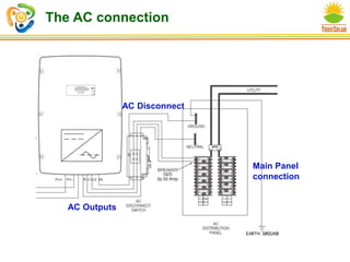
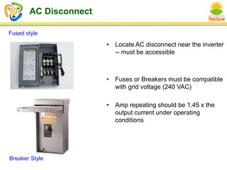
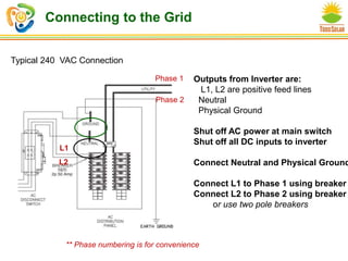
- Connecting the AC side to inverters, including AC disconnects, breakers, and grid connections while following safety procedures.
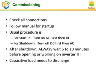
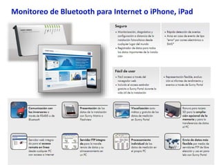
- Commissioning the system by turning components on in the proper sequence, conducting startup checks, and installing monitoring equipment.