Downloaded 135 times
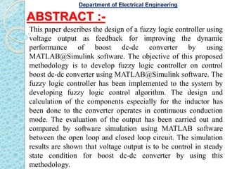

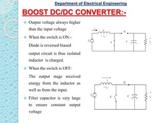


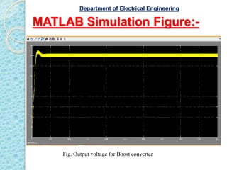


This document describes a study that designed a fuzzy logic controller for a boost DC-DC converter using MATLAB/Simulink software. The objective was to develop a fuzzy logic algorithm to control the output voltage of the boost converter in steady state conditions. Simulation results showed that the fuzzy logic controller was able to maintain the output voltage with no overshoot, unlike the open loop converter which had 80% overshoot. In conclusion, the fuzzy logic controller improved the dynamic performance and stability of the boost converter compared to an open loop design.