Downloaded 139 times


![TRANSMITTER BRIGHTNESS (RADIANCE)
• At the receiver, the quantity of interest is the irradiance, I(W/m2). The
irradiance depends on the transmitter brightness in the far field
– I(Z) = Io{( Db2/4)/[( Db2/4) + (t Z) 2/4]} ~ IoDb2/(t Z) 2 = L / Z 2
– where L = Io Db2/ ( t 2 /4) = Pt / ( t 2 /4) is the brightness (radiance)
– The transmitter brightness depends on the science and engineering of the laser
source, and for each type has fundamental limits
– Brighter transmitters provide better comm links with smaller transmit telescopes
• Narrow linewidth of the laser can improve receiver signal to noise ratio as
more of the background radiation can be filtered
– Linewidth or f =
– Ultra-narrow (kHz to GHz) or ( f / f less than 10-6) can use atomic filters
– Narrow (GHz to THz) can use optical bandpass filters
• The combination of high radiance and narrow linewidth produces high
spectral brightness, which makes the beam visible in ambient illumination
JPHPS - LCO2 24](https://image.slidesharecdn.com/laserradarandapplicationscoursesampler-101209134236-phpapp02/85/ATI-Laser-RADAR-and-Applications-Training-for-Advanced-Students-Course-Sampler-24-320.jpg)


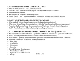
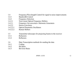
The document outlines a professional development course on laser communications, focusing on various aspects such as emerging challenges, DOD's roadmap, capabilities, and system requirements. It discusses the advantages of laser communications over traditional RF systems, highlights the latest technology and applications, and emphasizes the importance of understanding key components and transmission methods. Additionally, it explores future opportunities, challenges in development, and performance metrics within different operational contexts.