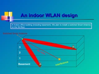
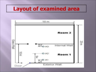
1) The document discusses using smart antennas for indoor wireless communication, including investigating wave propagation using a switched beam smart antenna in a simulated 4-story office building.
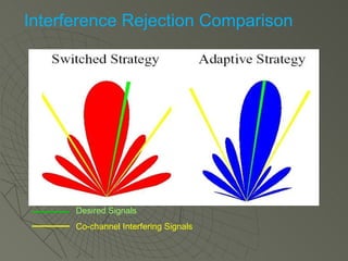
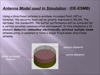
2) A smart antenna can maximize antenna gain towards desired signals while minimizing it for interferers, improving capacity, coverage, bit rate, and link quality over conventional antennas.
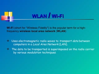
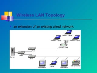
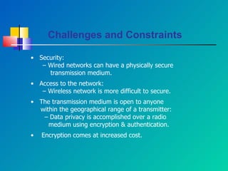
3) Wireless local area networks (WLANs) use radio waves to transport data between computers in a local area network, and challenges for indoor WLAN design include interference and security.


![DOC-20230719-WA0002wivi[1].doc important questions](https://cdn.slidesharecdn.com/ss_thumbnails/doc-20230719-wa0002wivi1-240109100415-1386cb3d-thumbnail.jpg?width=640&height=640&fit=bounds)

