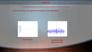
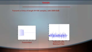
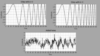
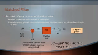
Matched Filter Detection 
Using lab view
Objectives(Tasks) 
Generation of 
chrip signal 
Generation 
of noisy 
wave form 
Matched 
filter 
detection 
• Generation of chirp signal 
• Generation of noisy wave form 
• Matched filter detection
2 
Matched Filter 
• Detection of pulse in presence of additive noise 
Receiver knows what pulse shape it is looking for 
Channel memory ignored (assumed compensated by other means, e.g. channel equalizer in 
receiver) 
Additive white Gaussian noise 
(AWGN) with zero mean and 
variance N0 /2 
g(t) 
Pulse 
signal 
w(t) 
x(t) 
h(t) 
y(t) 
t = T 
y(T) 
Matched 
filter 
y t g t h t w t h t 
( )  ( )* ( )  
( )* ( ) 
0 g t n t 
  
( ) ( ) 
T is pulse 
period
13 - 4 
Matched Filter 
• Given transmitter pulse shape g(t) of duration T, matched filter 
is given by hopt(t) = k g*(T-t) for all k 
Duration and shape of impulse response of the optimal filter is 
determined by pulse shape g(t) 
hopt(t) is scaled, time-reversed, and shifted version of g(t) 
• Optimal filter maximizes peak pulse SNR 
SNR 
2 
 
 
E 
b  
g t dt 
G f df 
    | ( ) | 
  
max 2 
| ( ) | 
2 
0 
2 
N 
 0 
2 
0 
 
N 
N 
Does not depend on pulse shape g(t) 
Proportional to signal energy (energy per bit) Eb 
Inversely proportional to power spectral density of noise
Typical Application: Radar 
Send a Pulse… 
] [ns 
n 
… and receive it back with noise, distortion … 
] [ny 
n 
0 n 
N 
Problem: estimate the time delay , ie detect when we receive it. 0 n
Use Inner Product 
“Slide” the pulse s[n] over the received signal and see when 
the inner product is maximum: 
s[] 
[ ]  [  
] * [ ] 
 
y[] 
 
0 n 
N 
n 
 
 
 
1 
0 
N 
ys r n y n s 
 
  
0 r [n] 0, if n n ys  
Use Inner Product 
“Slide” the pulse x[n] over the received signal and see when 
the inner product is maximum: 
 
* [ ] [ ] [ ] 
if 0 nnMAX s n y n r 
0 n   
s[] 
 
y[] 
 
N 
N 
ys    
 
1 
0 
 
 
Matched Filter 
Take the expression 
 
1 
* 
  
  
r n y n s 
[ ] [ ] [ ] 
0 
 
* * * 
s N y n N s y n s y n 
[ 1] [ 1] ... [1] [ 1] [0] [ ] 
N 
n 
ys 
        
Compare this, with the output of the following FIR Filter 
rˆ[n]  h[0]y[n]... h[1]y[n 1] h[N 1]y[n  N 1] 
Then 
y[n] h[n] 
rˆ[n]  r [n  N 1] ys 
[ ] [ 1 ], 0,..., 1 * h n  s N   n n  N 
Matched Filter 
This Filter is called a Matched Filter 
y[n] rˆ[n] 
] [nh 
[ ] [ 1 ], 0,..., 1 * h n  s N   n n  N  
The output is maximum when 
rˆ[n]  r [n  N 1] ys 
0 n  N 1 n 
1 0 i.e. n  n  N 
Example 
We transmit the pulse s [ n ] , n  0 , . . . , N  1 shown below, with 
length N  20 
0 2 4 6 8 10 12 14 16 18 20 
1 
0.8 
0.6 
0.4 
0.2 
0 
-0.2 
-0.4 
-0.6 
-0.8 
-1 
] [ns 
0 20 40 60 80 100 120 140 160 180 200 
12 
10 
8 
6 
4 
2 
0 
-2 
-4 
-6 
1.5 ] [ny 
1 
0.5 
0 
-0.5 
-1 
-1.5 
0 20 40 60 80 100 120 140 160 180 
-2 
y[n] rˆ[n] 
h[n] 
[ ] [ 1 ], 0,..., 1 * h n  s N   n n  N  
Received signal: 
Max at n=119 
119 20 1 100 0 n    
Example: Chirp 
r [n], n  49,...,49 ss 
0 5 10 15 20 25 30 35 40 45 50 
s[n],n  0,...,49 
1 
0.8 
0.6 
0.4 
0.2 
0 
-0.2 
-0.4 
-0.6 
-0.8 
-1 
30 
25 
20 
15 
10 
5 
0 
-5 
-10 
-50 -40 -30 -20 -10 0 10 20 30 40 50 
s=chirp(0:49,0,49,0.1)
Example 
Transmit a Chirp of length N=50 samples, with SNR=0dB 
0 50 100 150 200 250 300 
2 
1.5 
1 
0.5 
0 
-0.5 
-1 
-1.5 
-2 
0 200 400 600 800 1000 1200 
30 
25 
20 
15 
10 
5 
0 
-5 
-10 
-15 
Transmitted Detected with 
Matched Filter
Example 
Transmit a Chirp of length N=100 samples, with SNR=0dB 
0 50 100 150 200 250 300 
2 
1.5 
1 
0.5 
0 
-0.5 
-1 
-1.5 
-2 
0 200 400 600 800 1000 1200 
50 
40 
30 
20 
10 
0 
-10 
-20 
Transmitted Detected with 
Matched Filter
Matched filter detection

Matched filter detection

  • 1.
    Matched Filter Detection Using lab view
  • 2.
    Objectives(Tasks) Generation of chrip signal Generation of noisy wave form Matched filter detection • Generation of chirp signal • Generation of noisy wave form • Matched filter detection
  • 3.
    2 Matched Filter • Detection of pulse in presence of additive noise Receiver knows what pulse shape it is looking for Channel memory ignored (assumed compensated by other means, e.g. channel equalizer in receiver) Additive white Gaussian noise (AWGN) with zero mean and variance N0 /2 g(t) Pulse signal w(t) x(t) h(t) y(t) t = T y(T) Matched filter y t g t h t w t h t ( )  ( )* ( )  ( )* ( ) 0 g t n t   ( ) ( ) T is pulse period
  • 4.
    13 - 4 Matched Filter • Given transmitter pulse shape g(t) of duration T, matched filter is given by hopt(t) = k g*(T-t) for all k Duration and shape of impulse response of the optimal filter is determined by pulse shape g(t) hopt(t) is scaled, time-reversed, and shifted version of g(t) • Optimal filter maximizes peak pulse SNR SNR 2   E b  g t dt G f df     | ( ) |   max 2 | ( ) | 2 0 2 N  0 2 0  N N Does not depend on pulse shape g(t) Proportional to signal energy (energy per bit) Eb Inversely proportional to power spectral density of noise
  • 5.
    Typical Application: Radar Send a Pulse… ] [ns n … and receive it back with noise, distortion … ] [ny n 0 n N Problem: estimate the time delay , ie detect when we receive it. 0 n
  • 6.
    Use Inner Product “Slide” the pulse s[n] over the received signal and see when the inner product is maximum: s[] [ ]  [  ] * [ ]  y[]  0 n N n    1 0 N ys r n y n s    0 r [n] 0, if n n ys  
  • 7.
    Use Inner Product “Slide” the pulse x[n] over the received signal and see when the inner product is maximum:  * [ ] [ ] [ ] if 0 nnMAX s n y n r 0 n   s[]  y[]  N N ys     1 0   
  • 8.
    Matched Filter Takethe expression  1 *     r n y n s [ ] [ ] [ ] 0  * * * s N y n N s y n s y n [ 1] [ 1] ... [1] [ 1] [0] [ ] N n ys         Compare this, with the output of the following FIR Filter rˆ[n]  h[0]y[n]... h[1]y[n 1] h[N 1]y[n  N 1] Then y[n] h[n] rˆ[n]  r [n  N 1] ys [ ] [ 1 ], 0,..., 1 * h n  s N   n n  N 
  • 9.
    Matched Filter ThisFilter is called a Matched Filter y[n] rˆ[n] ] [nh [ ] [ 1 ], 0,..., 1 * h n  s N   n n  N  The output is maximum when rˆ[n]  r [n  N 1] ys 0 n  N 1 n 1 0 i.e. n  n  N 
  • 10.
    Example We transmitthe pulse s [ n ] , n  0 , . . . , N  1 shown below, with length N  20 0 2 4 6 8 10 12 14 16 18 20 1 0.8 0.6 0.4 0.2 0 -0.2 -0.4 -0.6 -0.8 -1 ] [ns 0 20 40 60 80 100 120 140 160 180 200 12 10 8 6 4 2 0 -2 -4 -6 1.5 ] [ny 1 0.5 0 -0.5 -1 -1.5 0 20 40 60 80 100 120 140 160 180 -2 y[n] rˆ[n] h[n] [ ] [ 1 ], 0,..., 1 * h n  s N   n n  N  Received signal: Max at n=119 119 20 1 100 0 n    
  • 11.
    Example: Chirp r[n], n  49,...,49 ss 0 5 10 15 20 25 30 35 40 45 50 s[n],n  0,...,49 1 0.8 0.6 0.4 0.2 0 -0.2 -0.4 -0.6 -0.8 -1 30 25 20 15 10 5 0 -5 -10 -50 -40 -30 -20 -10 0 10 20 30 40 50 s=chirp(0:49,0,49,0.1)
  • 12.
    Example Transmit aChirp of length N=50 samples, with SNR=0dB 0 50 100 150 200 250 300 2 1.5 1 0.5 0 -0.5 -1 -1.5 -2 0 200 400 600 800 1000 1200 30 25 20 15 10 5 0 -5 -10 -15 Transmitted Detected with Matched Filter
  • 13.
    Example Transmit aChirp of length N=100 samples, with SNR=0dB 0 50 100 150 200 250 300 2 1.5 1 0.5 0 -0.5 -1 -1.5 -2 0 200 400 600 800 1000 1200 50 40 30 20 10 0 -10 -20 Transmitted Detected with Matched Filter