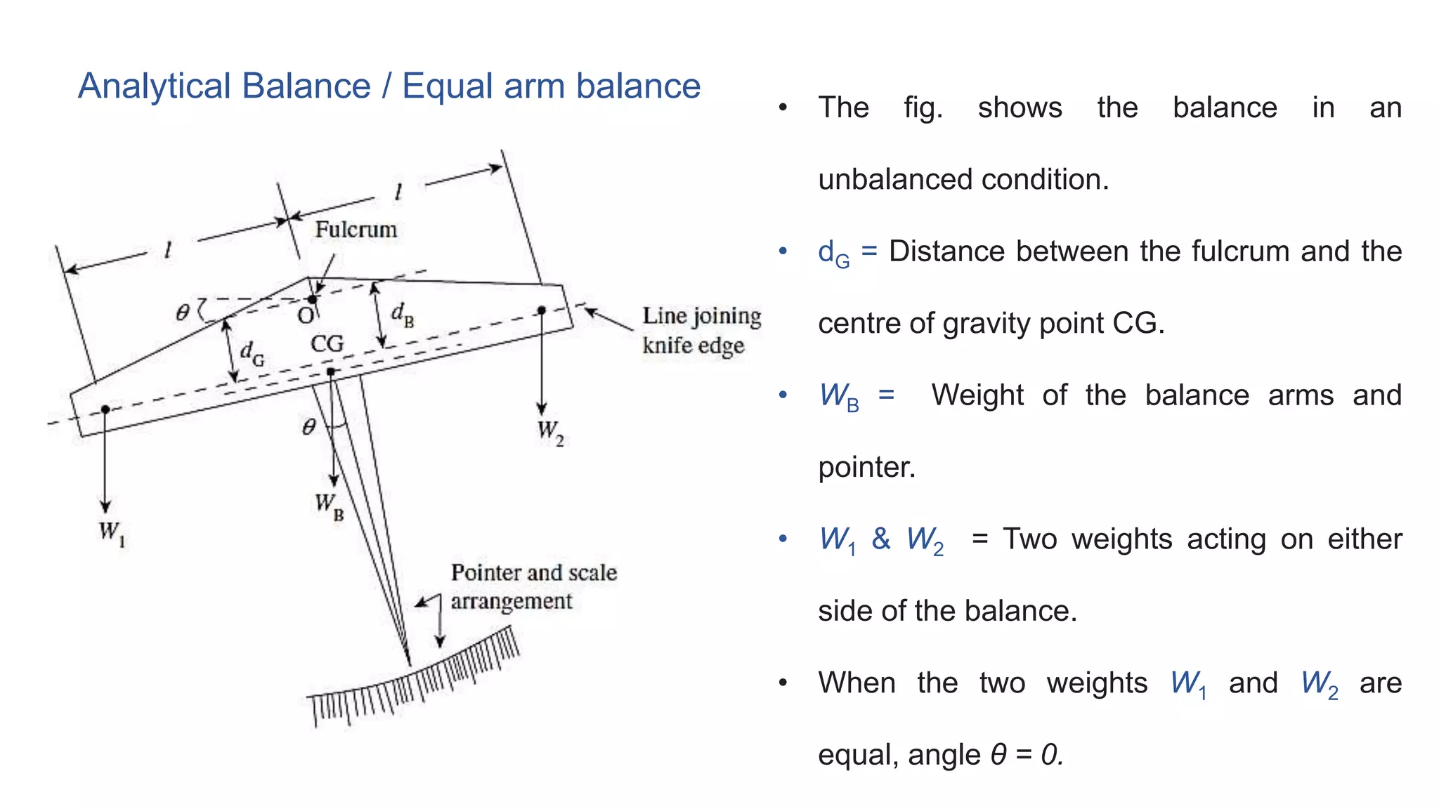
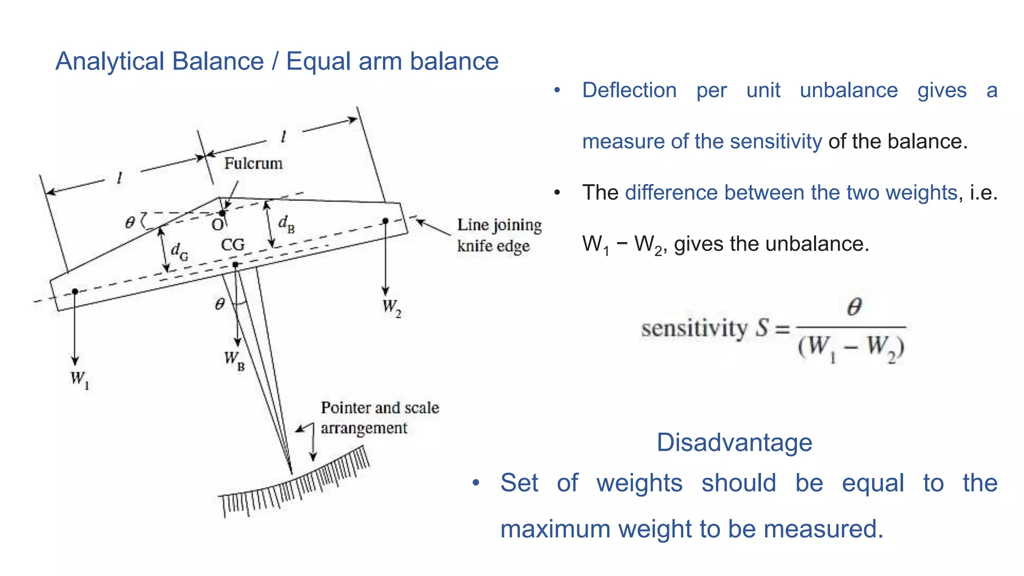
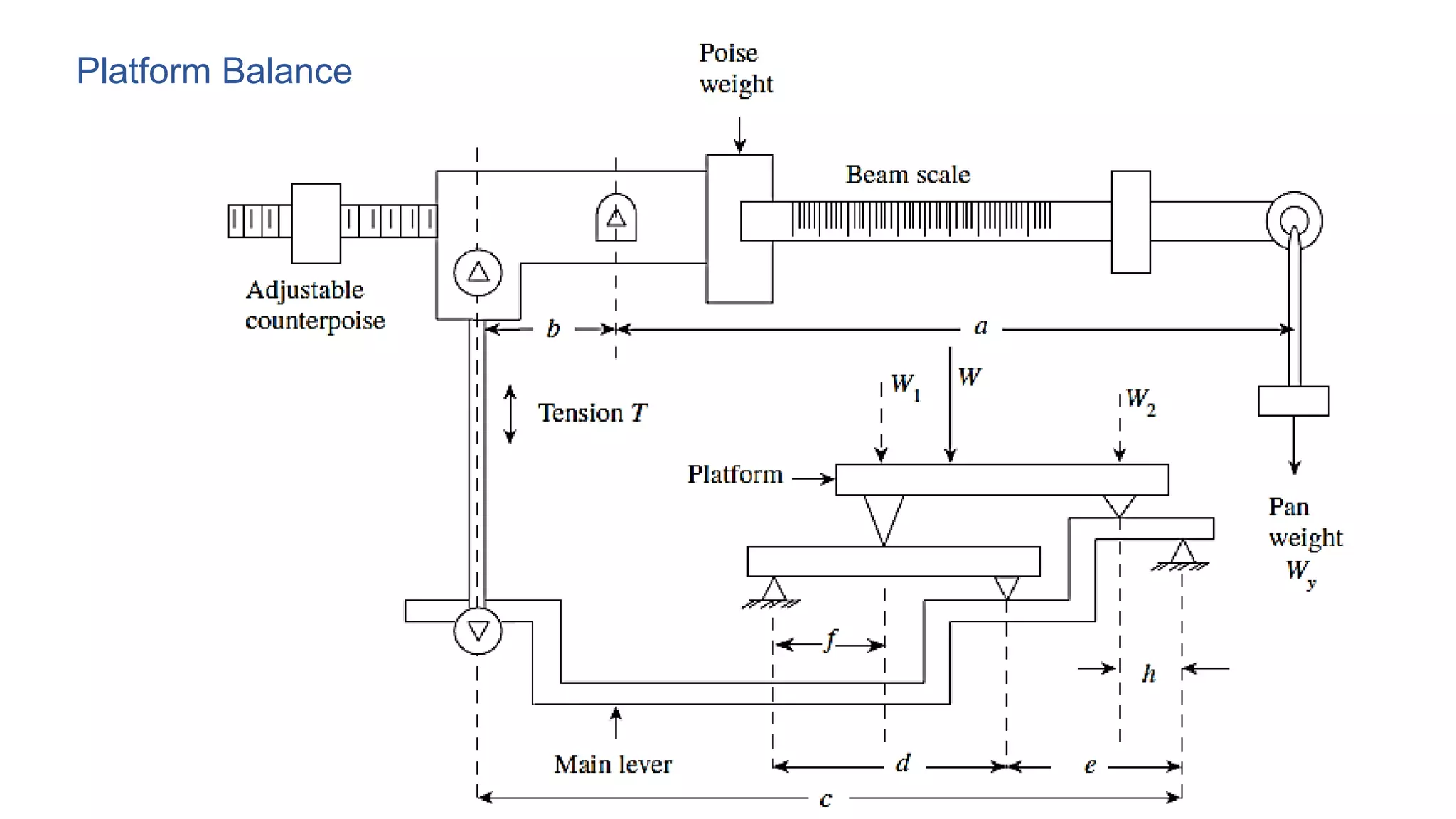
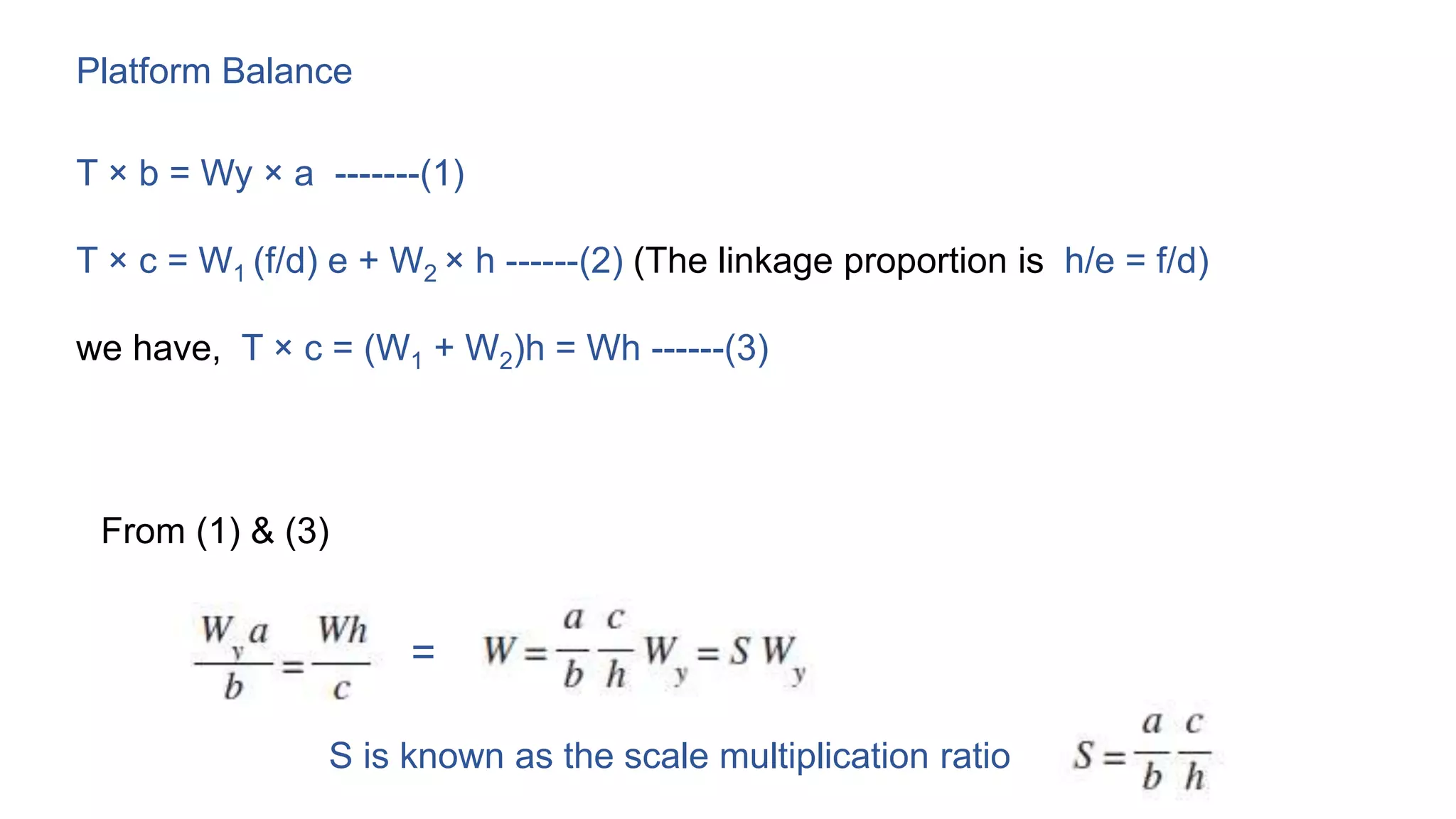
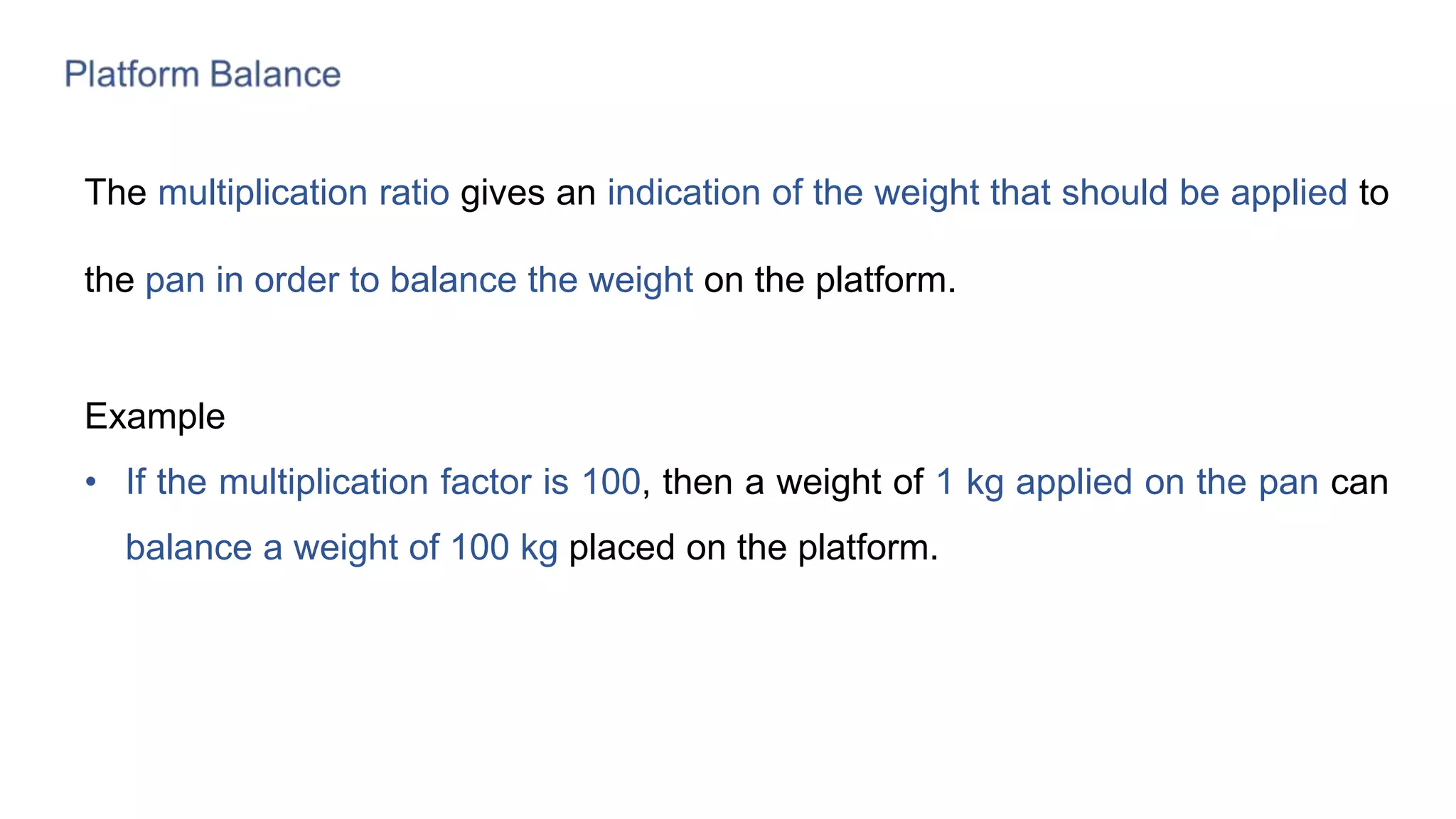
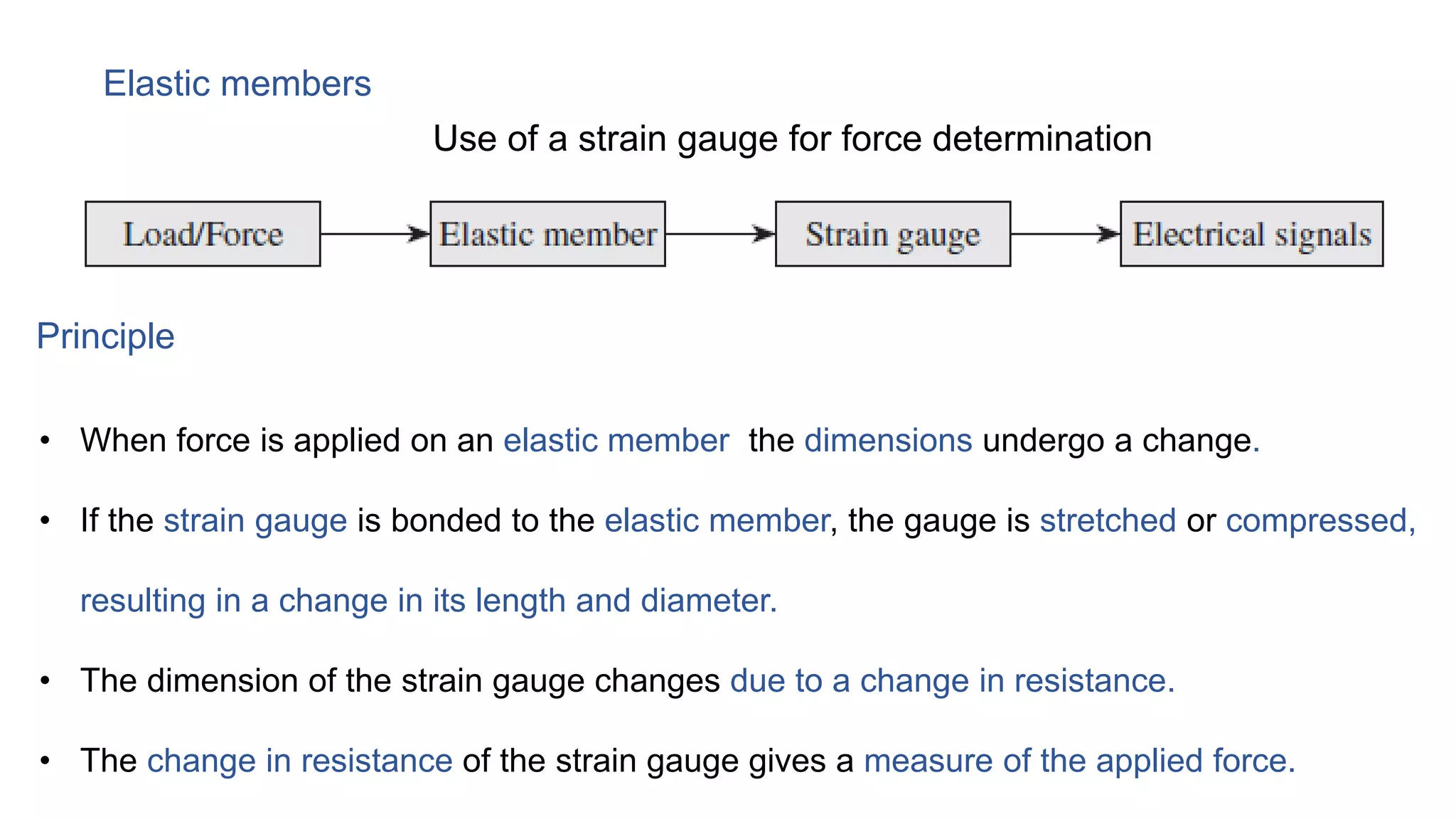
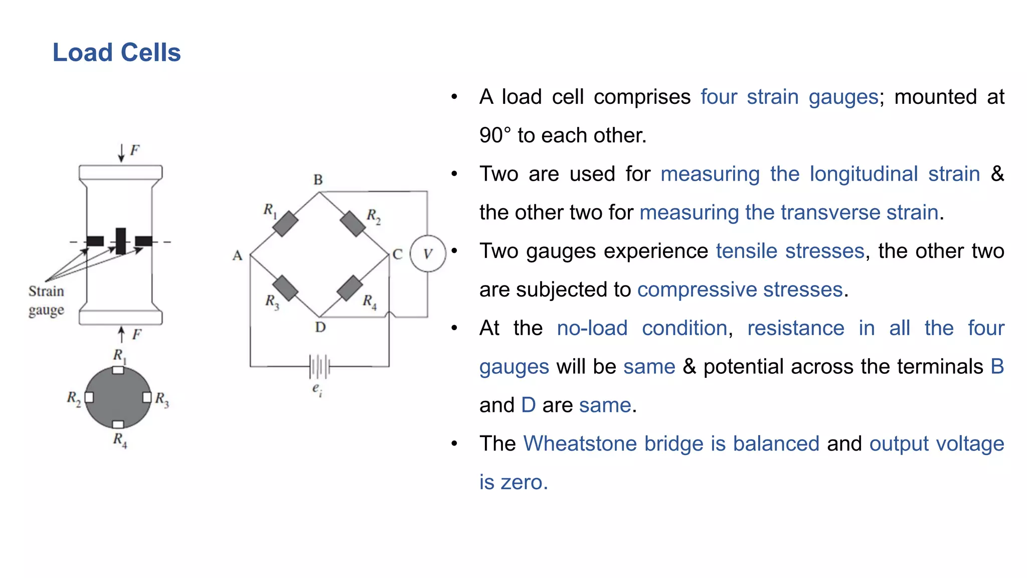
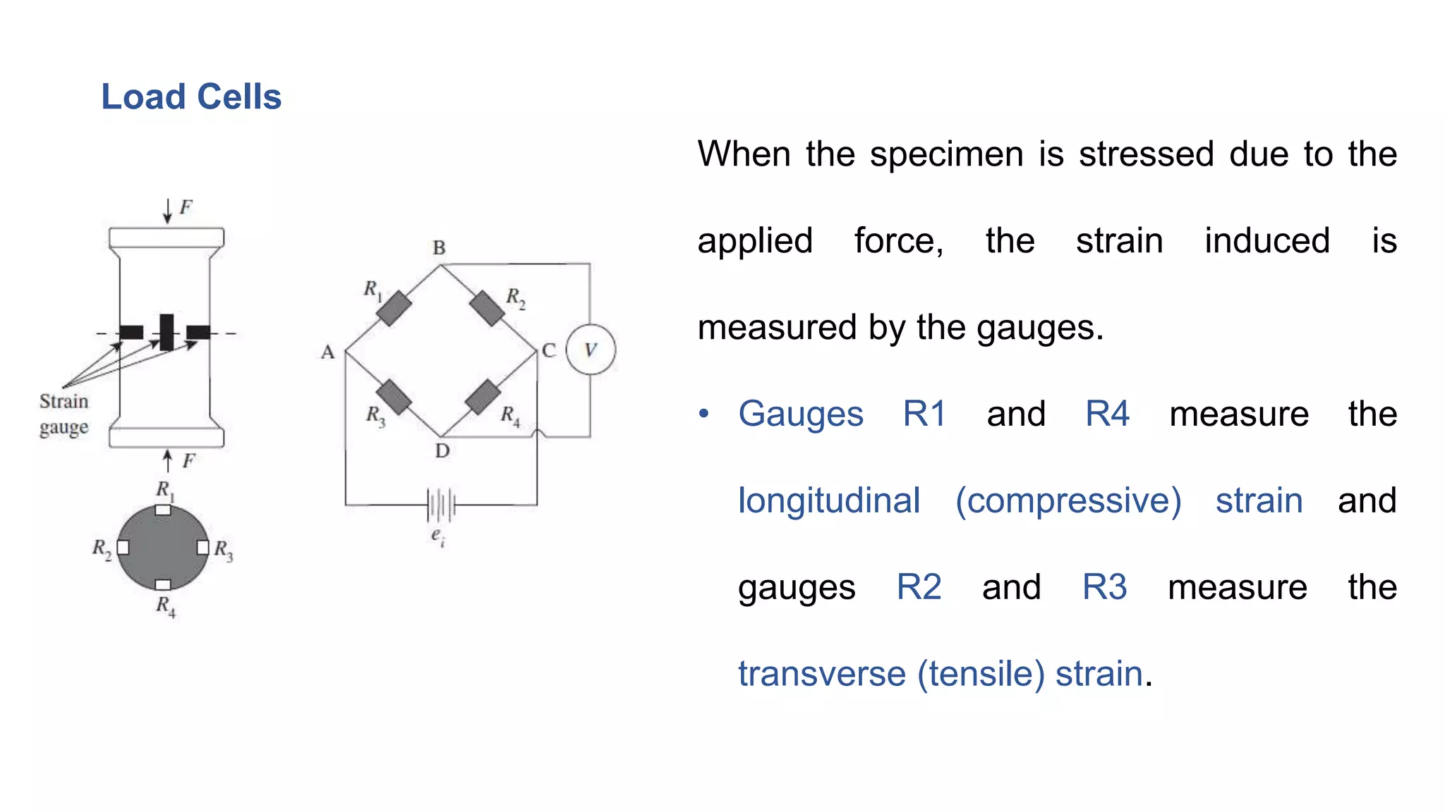
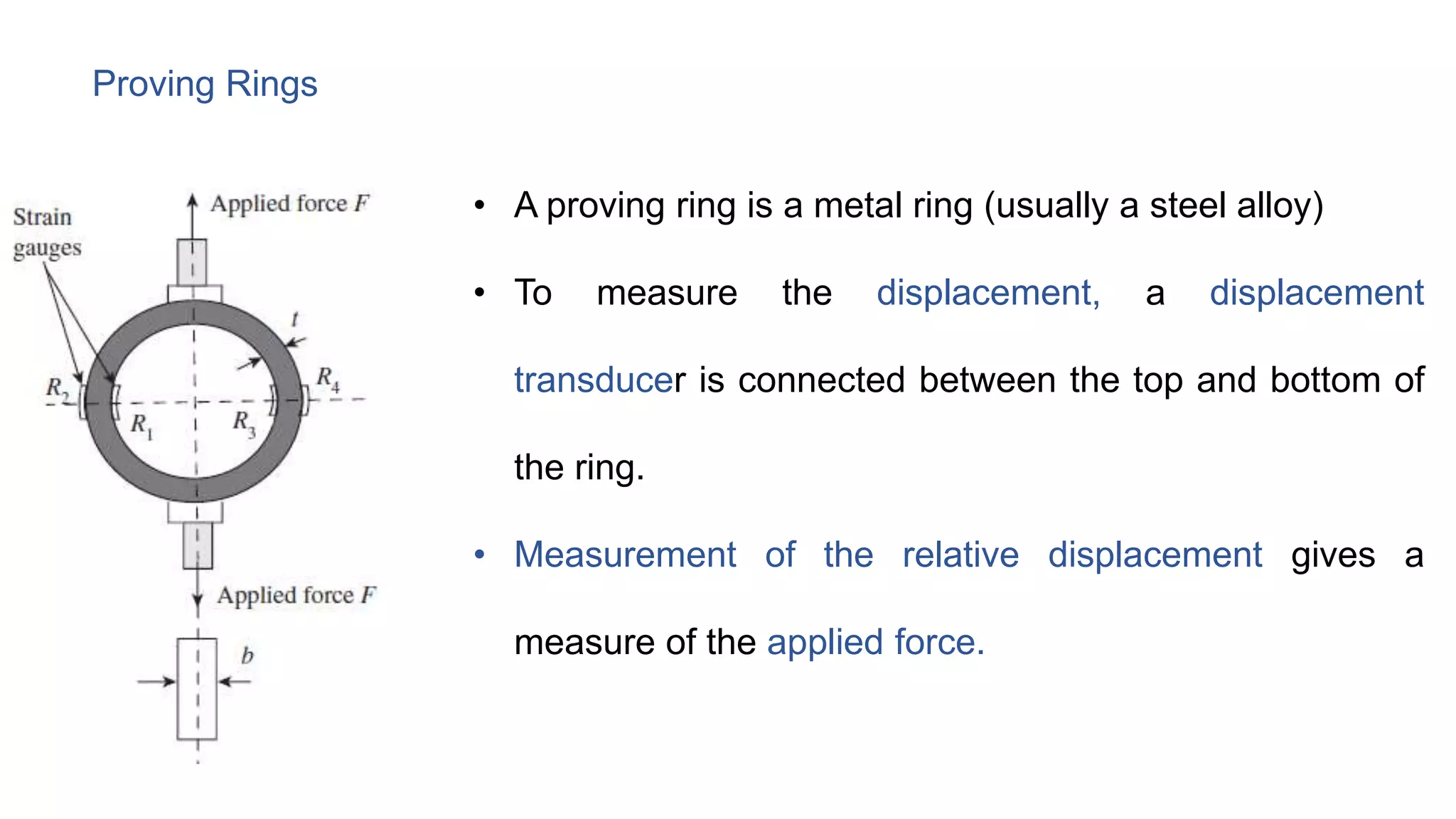
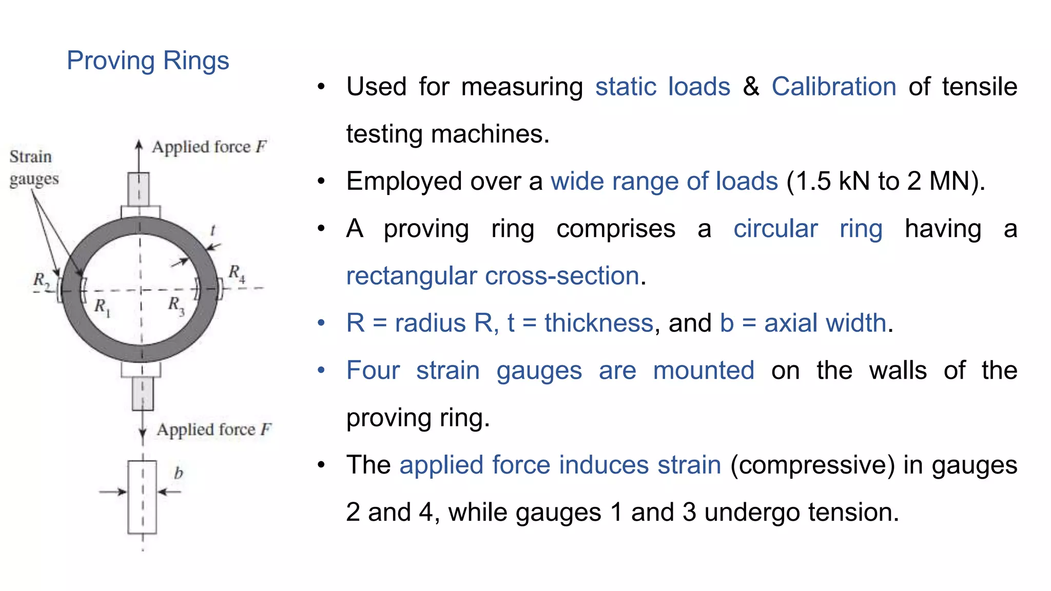
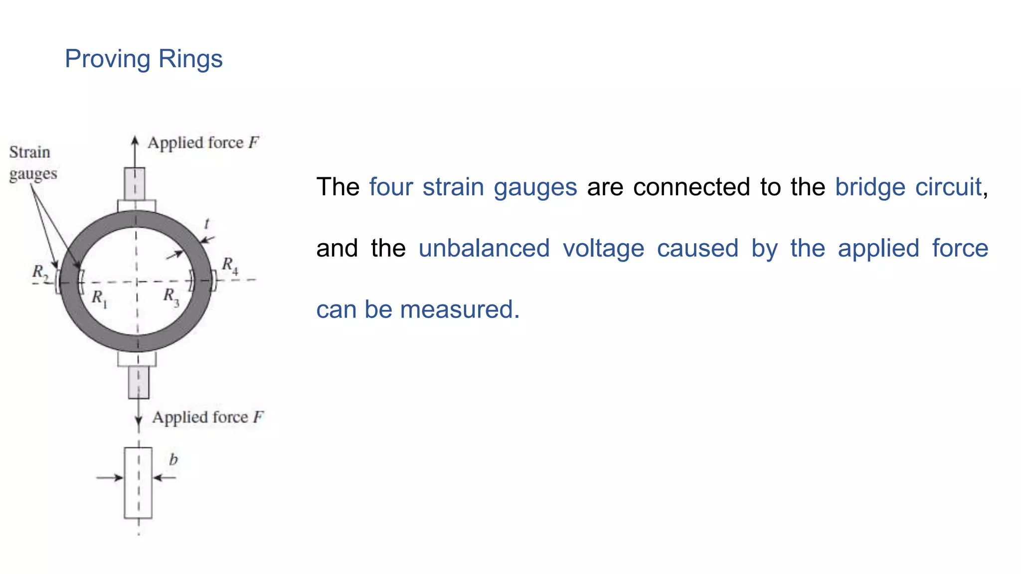
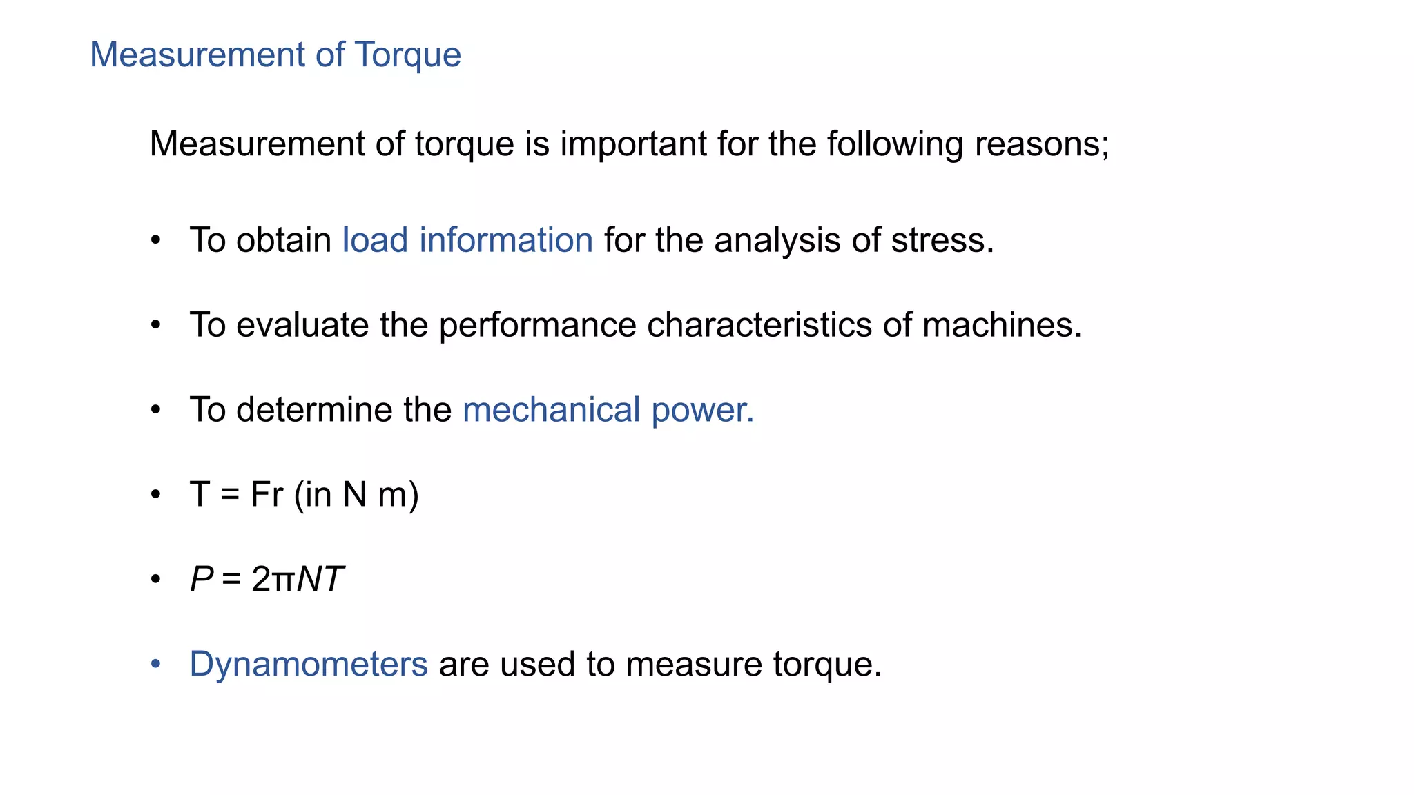
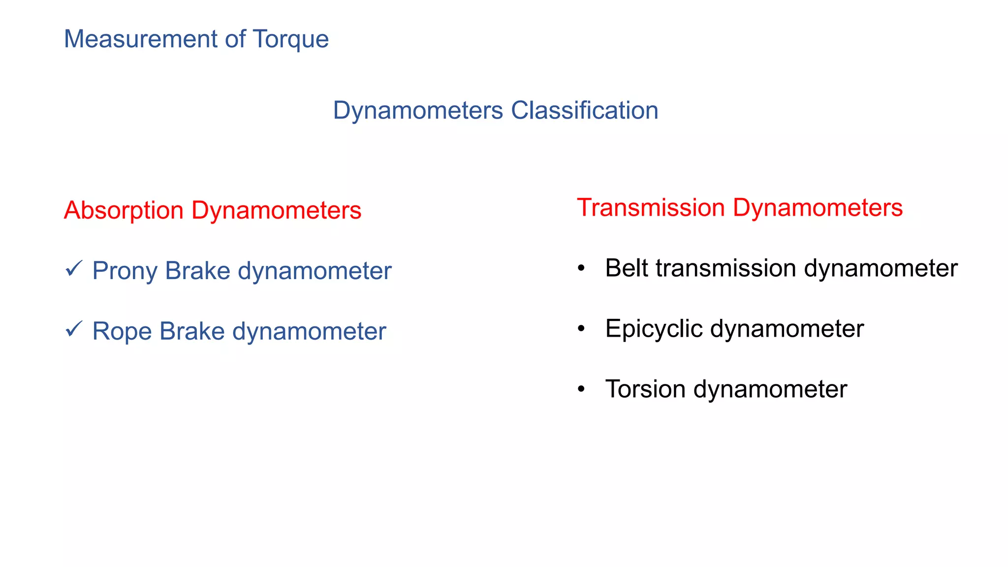
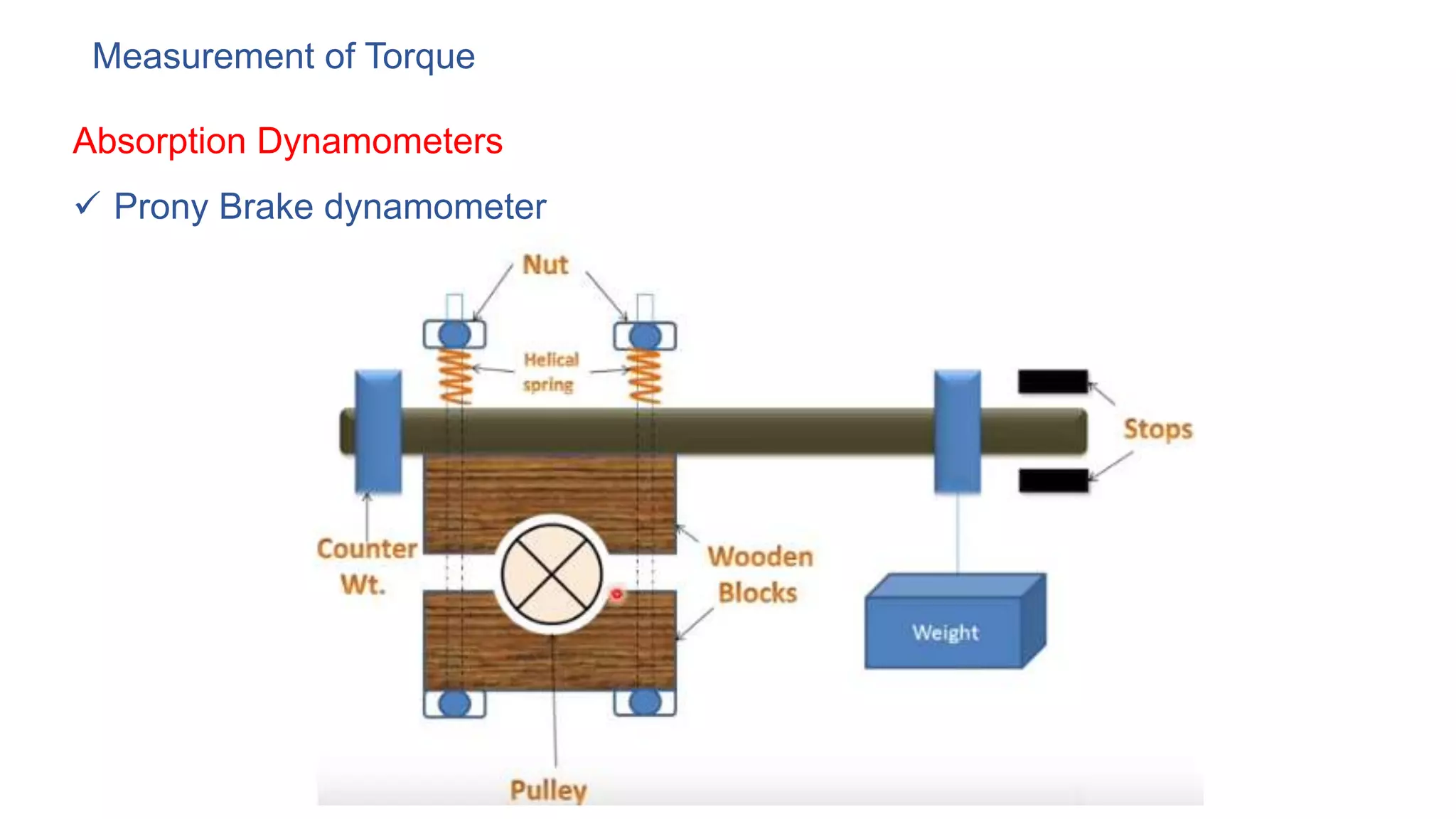
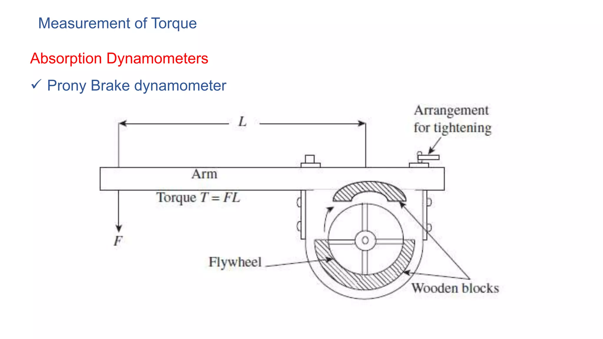
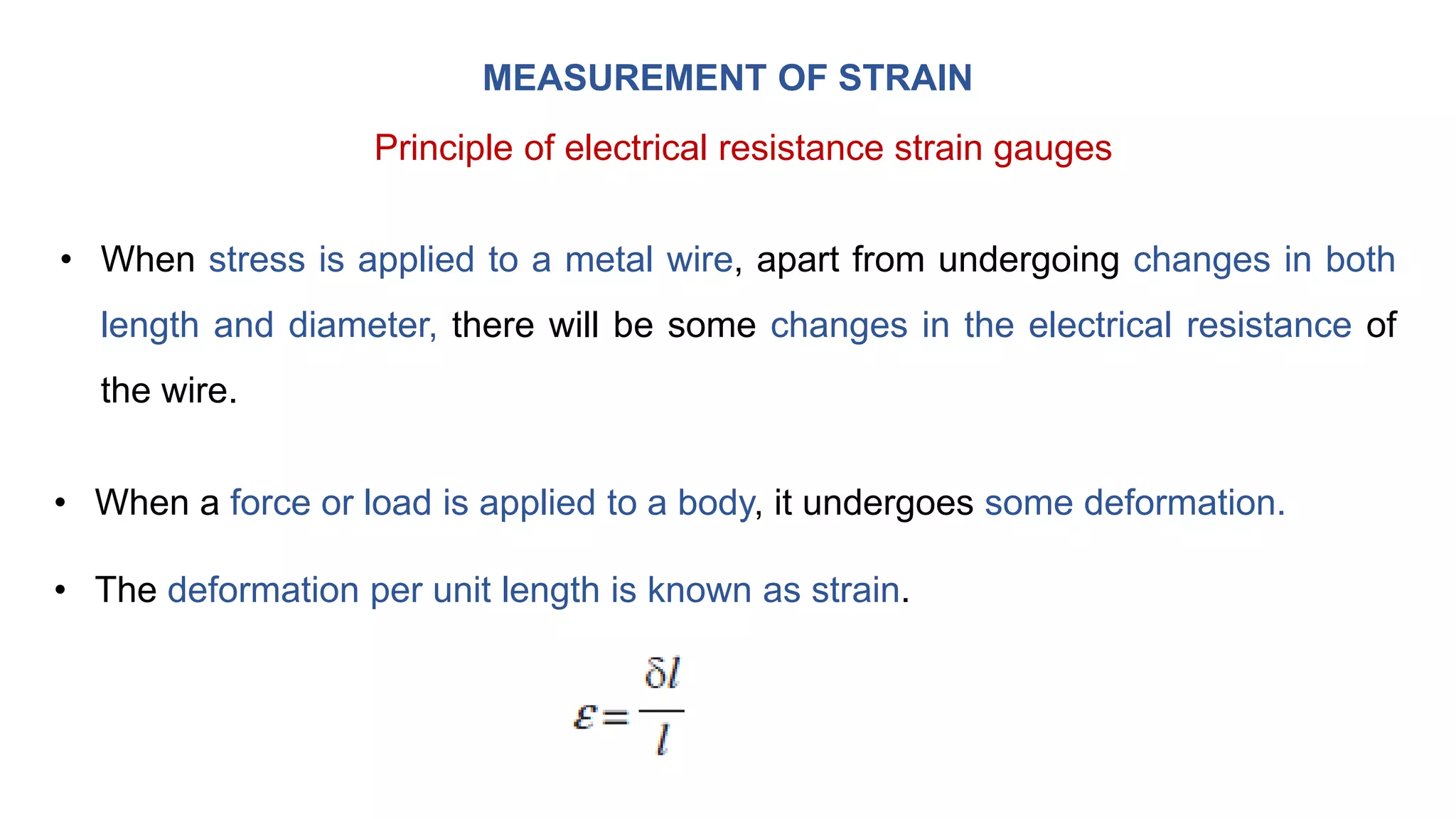
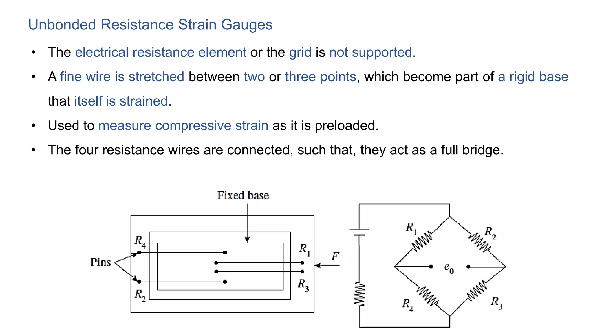
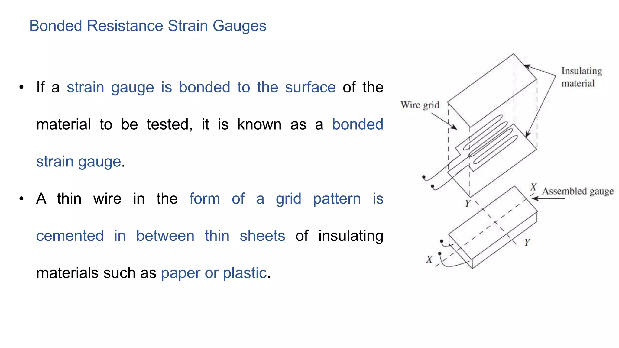
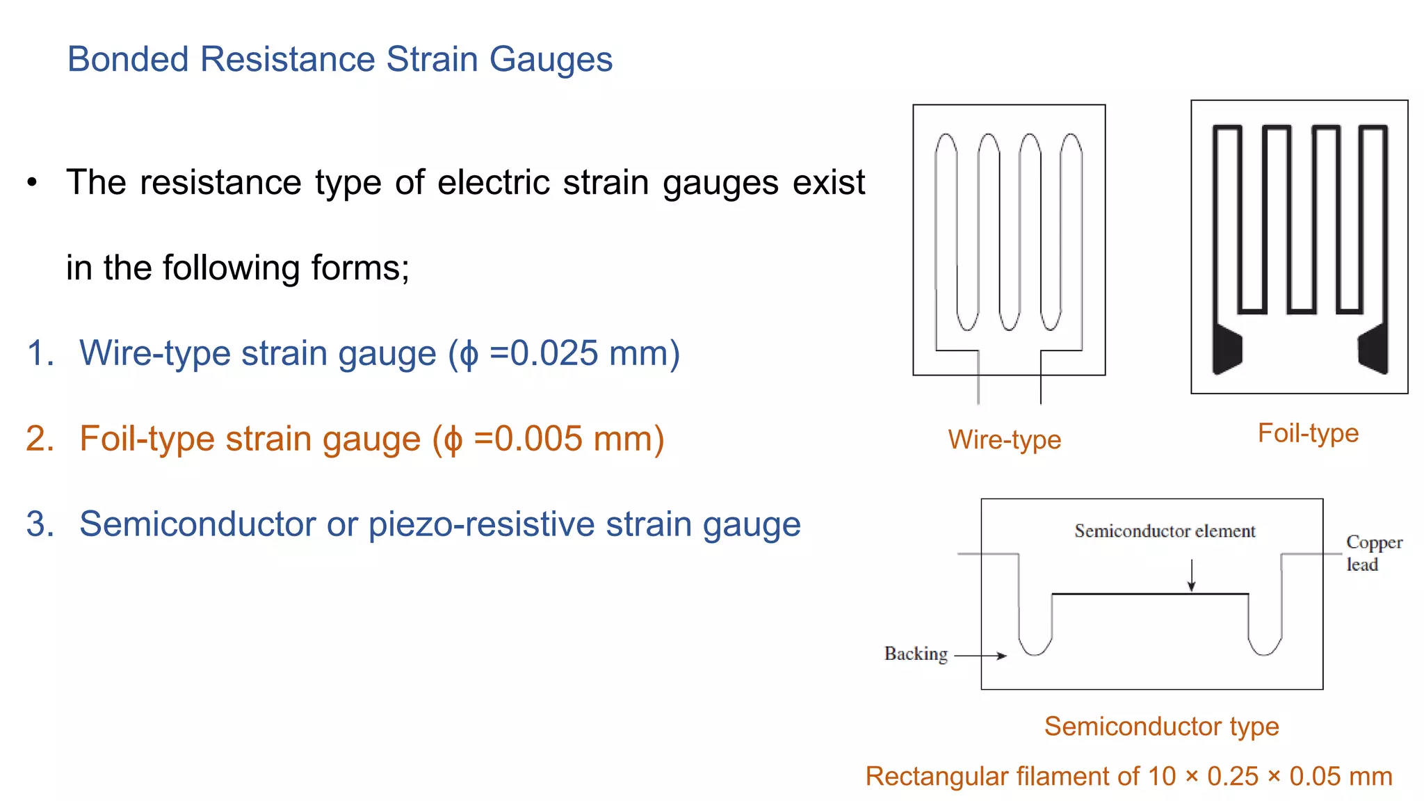
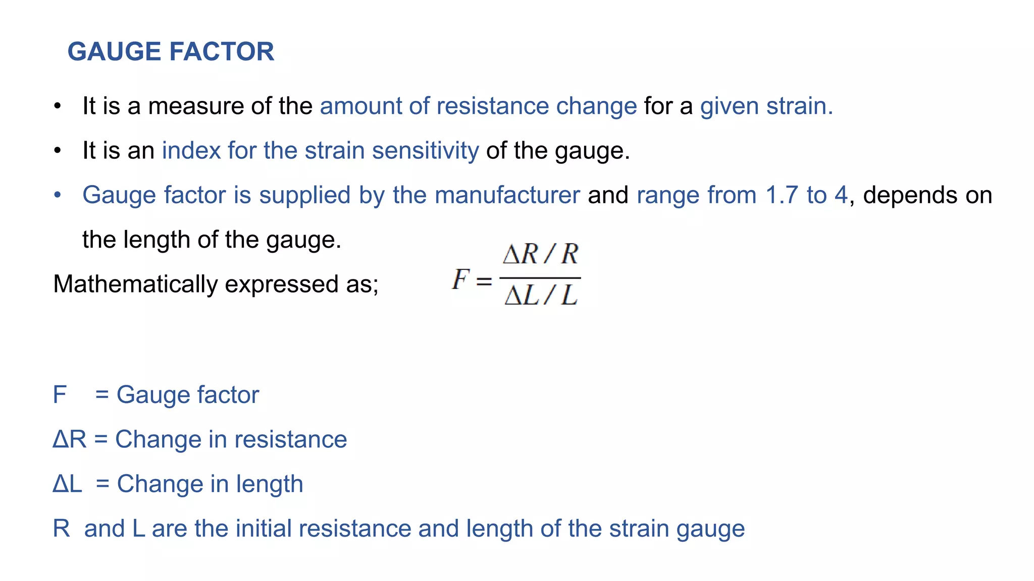
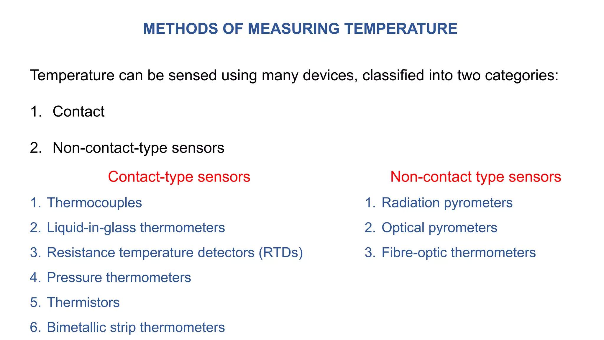
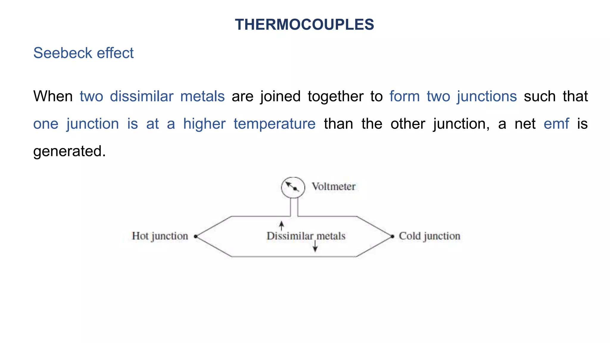
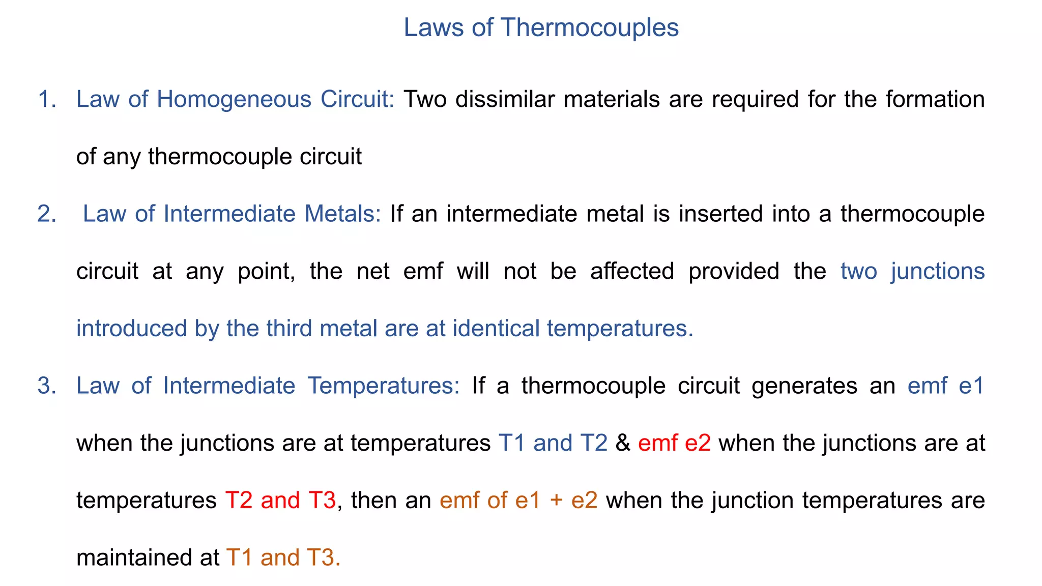
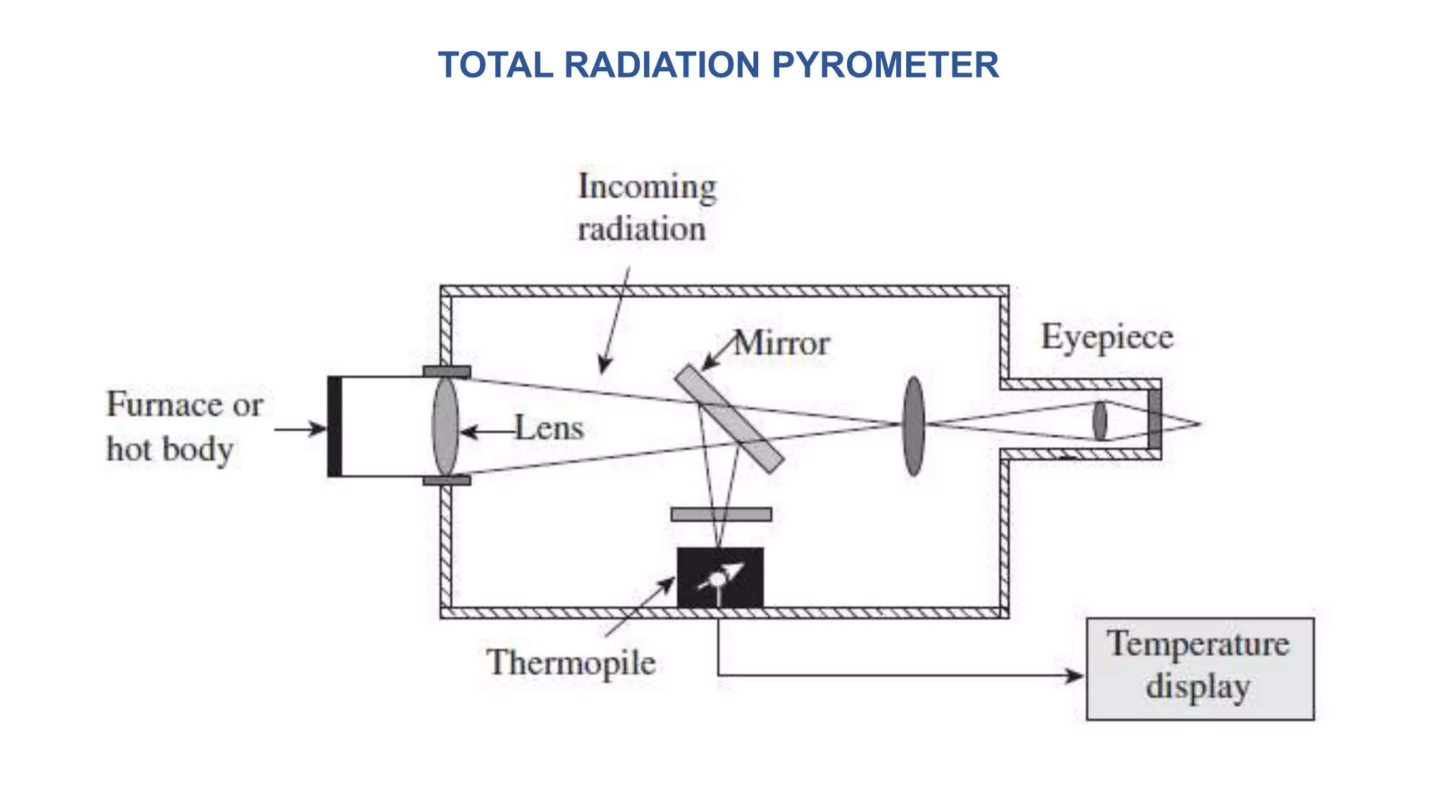
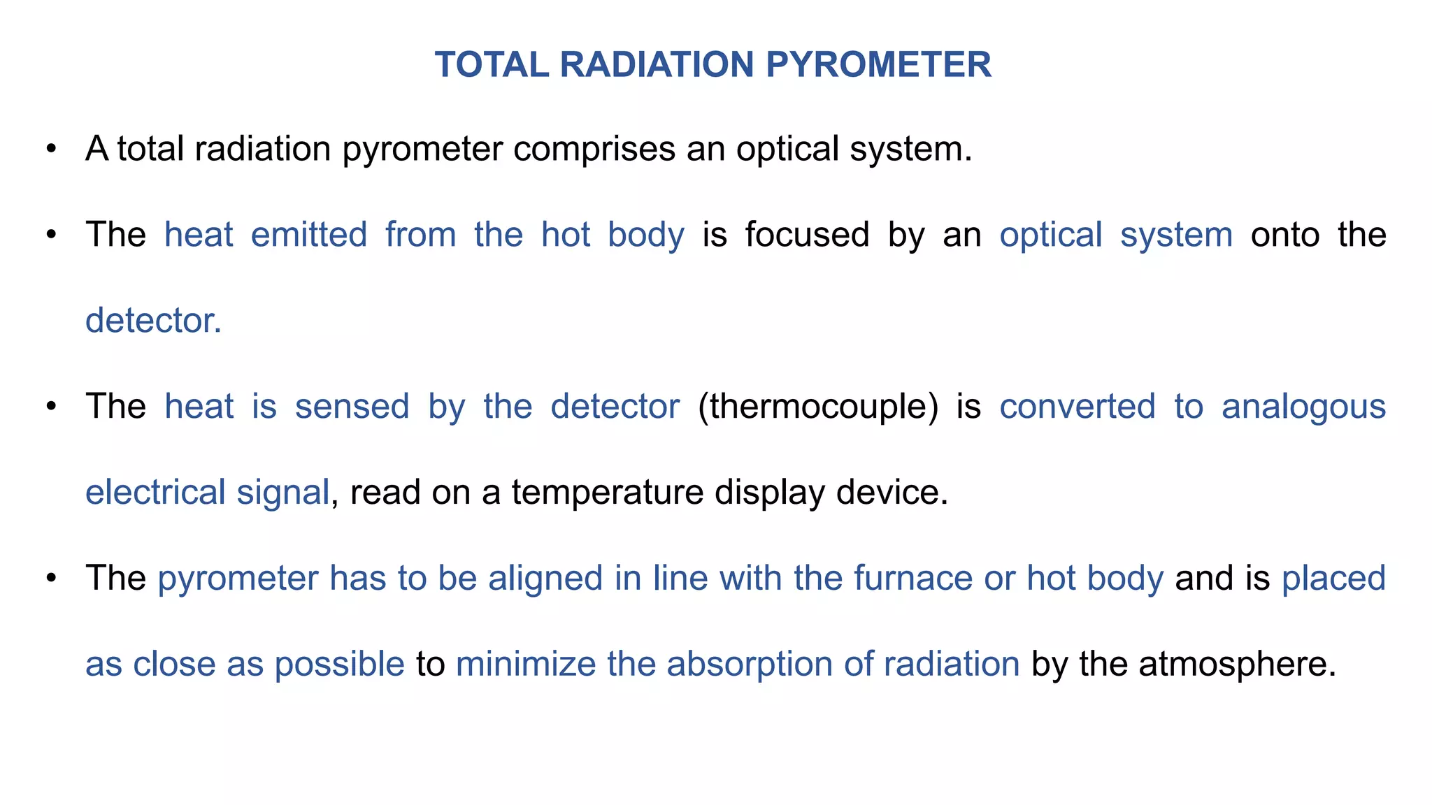
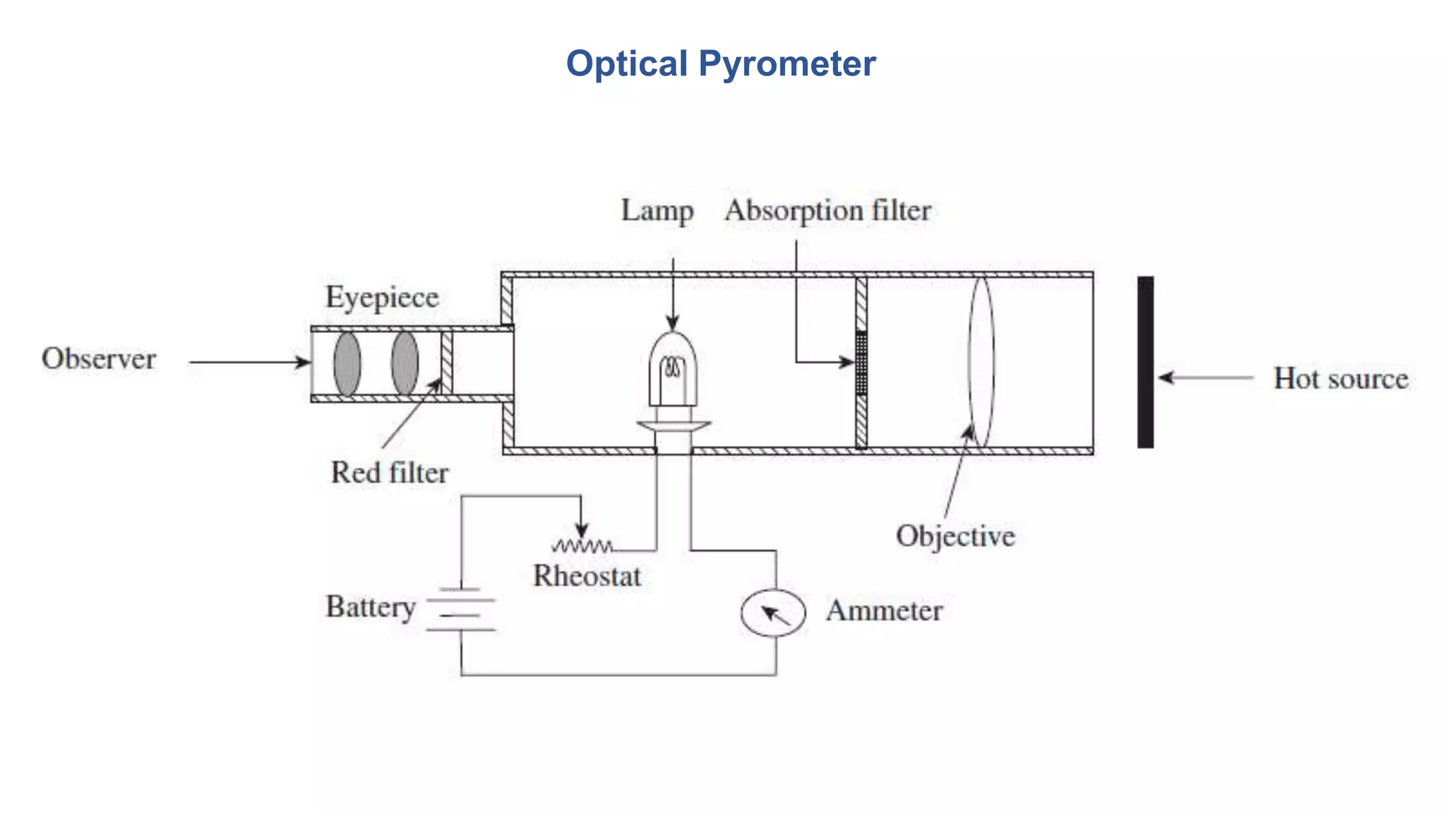
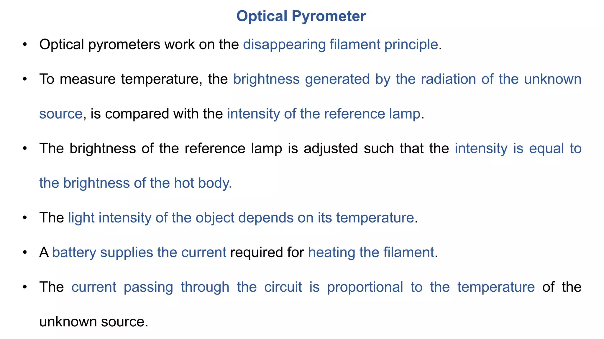
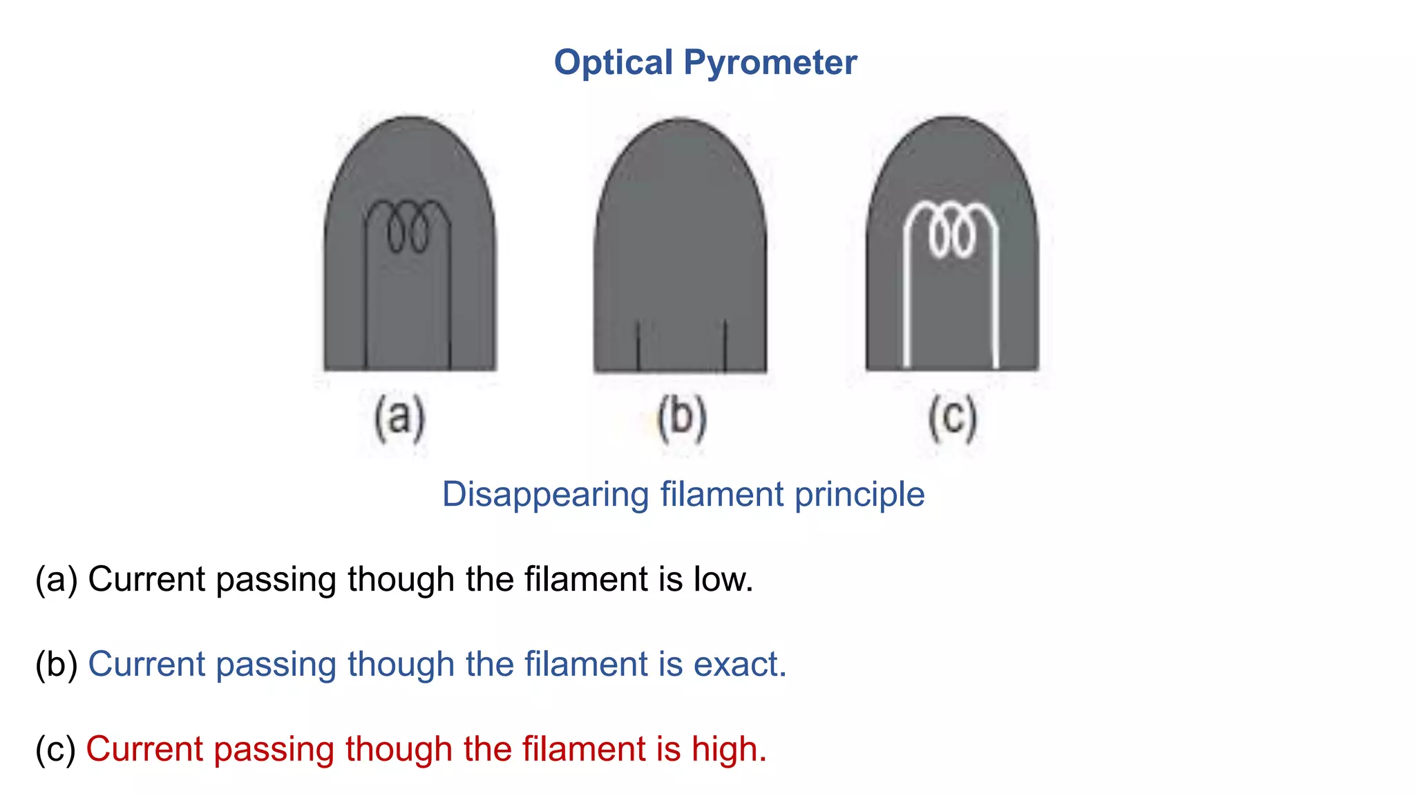
This document provides an overview of mechanical measurements and metrology. It discusses various methods for measuring force, torque, strain, and temperature. For force measurement, it describes direct methods using analytical balances and platform balances, as well as indirect methods using load cells and proving rings with strain gauges. Torque measurement uses dynamometers like the Prony brake. Strain is measured using electrical resistance strain gauges. Temperature is sensed using contact sensors like thermocouples and resistance temperature detectors or non-contact sensors like pyrometers.
Surface roughness metrology deals with basic terminology of surface,surface roughness indication methods,analysis of surface traces, measurement methods,surface roughness measuring instruments such as Stylus Probe Instrument, Profilometer, Tomlinson Surface Meter ,The Taylor-Hobson Talysurf etc.This is very useful for diploma,degree engineering students of mechanical,production,automobile branch
Introduction to Mechanical Measurements and Metrology taruian
Introduction to Metrology: Definition, objectives of metrology, Material Standards, Wavelength Standards, Classification of standards, Line and End standards, Calibration of End bars. Numerical examples.
This presentation gives the information about Screw thread measurements and Gear measurement of the subject: Mechanical measurement and Metrology (10ME32/42) of VTU Syllabus covering unit-4.
1. Measuring the angle of a component.
2. Checking the sloping angle of a vee-block.
3. Measuring the angle of a cone or taper gauges.
4. Precise angular settings for machining operations.
the above PPT will give a brief idea of the measuring device used in the field of Mechanical Engineering with images related to the topics in the field of measurement.
Basic civil Mechanical Engineering Subject full notes according to JNTUAMOKSHIT TECH
Basic Definitions of Force – Stress – Strain – Elasticity. Shear force – Bending Moment –
Torsion . Simple problems on Shear force Diagram and Bending moment Diagram for cantilever and simply supported beams.
Measurement of force and torque and pressure standardsMech-4u
Measurement of Force and Torque and pressure Standards,
Measuring Methods,
study of different types of forces and torque Measuring systems.
Description and working Principle of different types of Transducers for Measuring Pressure.
This ppt contains the information regarding the measurement of force and various instruments that are used for the measurement of force. This a topic in the fifth unit of Metrology and instrumentation for the third mechanical in JNTUACEP.
for detailed information or video of this ppt just follow the youtube link attached below
https://youtu.be/aCMXmWc2poU
Introduction_Medical Robotics
Types of medical robots - Navigation - Motion Replication - Imaging - Rehabilitation and Prosthetics - State of art of robotics in the field of healthcare
Introduction to OS
Basic Principles, Operating System Structures, System Calls & Types, Processes: Concept Scheduling - Inter
Process Communication, Introduction to Distributed Operating System, Types of network based OS.
Robot Drives And End Effectors
Robot drive systems: Hydraulic, Pneumatic and Electric drive
systems, classification of end effectors, mechanical grippers, vacuum grippers, magnetic grippers,
adhesive gripper, gripper force analysis and gripper design
Robot Anatomy And Motion Analysis
Anatomy of a Robot, Robot configurations: polar, cylindrical,
Cartesian, and jointed arm configurations, Robot links and joints, Degrees of freedom: types of
movements, vertical, radial and rotational traverse, roll, pitch and yaw, Wok volume/envelope, Robot
kinematics: Introduction to direct and inverse kinematics, transformations and rotation matrix
Avoiding Risk & Harmful Habits
Characteristics of health compromising behaviors, Recognizing and avoiding of
addictions, How addiction develops, Types of addictions, influencing factors of addictions, Differences between addictive
people and non addictive people & their behaviors. Effects of addictions
Creating Healthy & Caring Relationships
Building communication skills, Friends and friendship - Education,
the value of relationship and communication skills, Relationships for Better or worsening of life, understanding of basic
instincts of life (more than a biology), Changing health behaviours through social engineering
Building Healthy Life Style for Better Future.pptxtaruian
Building Healthy Life Style for Better Future
Developing healthy diet for good health, Food & health, Nutritional
guidelines for good health, Obesity & overweight disorders and its management, Eating disorders, Fitness components for
health, Wellness and physical function, How to avoid exercise injuries
Good Health & It’s balance for positive mindset.pptxtaruian
Health -Importance of Health, Influencing factors of Health,
Health beliefs, Advantages of good health, Health & Behavior, Health & Society, Health & family, Health & Personality,
Psychological disorders-Methods to improve good psychological health, Changing health habits for good health
Thread terminology, sectional views of threads. ISO Metric (Internal & External), BSW (Internal & External), Square and Acme, Sellers thread, American Standard thread.
IoT Processing Topologies and Types: Data Format, Importance of Processing in IoT, Processing Topologies, IoT Device Design and Selection Considerations, Processing Offloading.
Introduction to IoT (Basics of Networking & Emergence of IoT).pptxtaruian
Basics of Networking: Introduction, Network Types, Layered network models.
Emergence of IoT: Introduction, Evolution of IoT, Enabling IoT and the Complex Interdependence of Technologies, IoT Networking Components.
About
Indigenized remote control interface card suitable for MAFI system CCR equipment. Compatible for IDM8000 CCR. Backplane mounted serial and TCP/Ethernet communication module for CCR remote access. IDM 8000 CCR remote control on serial and TCP protocol.
• Remote control: Parallel or serial interface.
• Compatible with MAFI CCR system.
• Compatible with IDM8000 CCR.
• Compatible with Backplane mount serial communication.
• Compatible with commercial and Defence aviation CCR system.
• Remote control system for accessing CCR and allied system over serial or TCP.
• Indigenized local Support/presence in India.
• Easy in configuration using DIP switches.
Technical Specifications
Indigenized remote control interface card suitable for MAFI system CCR equipment. Compatible for IDM8000 CCR. Backplane mounted serial and TCP/Ethernet communication module for CCR remote access. IDM 8000 CCR remote control on serial and TCP protocol.
Key Features
Indigenized remote control interface card suitable for MAFI system CCR equipment. Compatible for IDM8000 CCR. Backplane mounted serial and TCP/Ethernet communication module for CCR remote access. IDM 8000 CCR remote control on serial and TCP protocol.
• Remote control: Parallel or serial interface
• Compatible with MAFI CCR system
• Copatiable with IDM8000 CCR
• Compatible with Backplane mount serial communication.
• Compatible with commercial and Defence aviation CCR system.
• Remote control system for accessing CCR and allied system over serial or TCP.
• Indigenized local Support/presence in India.
Application
• Remote control: Parallel or serial interface.
• Compatible with MAFI CCR system.
• Compatible with IDM8000 CCR.
• Compatible with Backplane mount serial communication.
• Compatible with commercial and Defence aviation CCR system.
• Remote control system for accessing CCR and allied system over serial or TCP.
• Indigenized local Support/presence in India.
• Easy in configuration using DIP switches.
Welcome to WIPAC Monthly the magazine brought to you by the LinkedIn Group Water Industry Process Automation & Control.
In this month's edition, along with this month's industry news to celebrate the 13 years since the group was created we have articles including
A case study of the used of Advanced Process Control at the Wastewater Treatment works at Lleida in Spain
A look back on an article on smart wastewater networks in order to see how the industry has measured up in the interim around the adoption of Digital Transformation in the Water Industry.
Explore the innovative world of trenchless pipe repair with our comprehensive guide, "The Benefits and Techniques of Trenchless Pipe Repair." This document delves into the modern methods of repairing underground pipes without the need for extensive excavation, highlighting the numerous advantages and the latest techniques used in the industry.
Learn about the cost savings, reduced environmental impact, and minimal disruption associated with trenchless technology. Discover detailed explanations of popular techniques such as pipe bursting, cured-in-place pipe (CIPP) lining, and directional drilling. Understand how these methods can be applied to various types of infrastructure, from residential plumbing to large-scale municipal systems.
Ideal for homeowners, contractors, engineers, and anyone interested in modern plumbing solutions, this guide provides valuable insights into why trenchless pipe repair is becoming the preferred choice for pipe rehabilitation. Stay informed about the latest advancements and best practices in the field.
Sachpazis:Terzaghi Bearing Capacity Estimation in simple terms with Calculati...Dr.Costas Sachpazis
Terzaghi's soil bearing capacity theory, developed by Karl Terzaghi, is a fundamental principle in geotechnical engineering used to determine the bearing capacity of shallow foundations. This theory provides a method to calculate the ultimate bearing capacity of soil, which is the maximum load per unit area that the soil can support without undergoing shear failure. The Calculation HTML Code included.
Overview of the fundamental roles in Hydropower generation and the components involved in wider Electrical Engineering.
This paper presents the design and construction of hydroelectric dams from the hydrologist’s survey of the valley before construction, all aspects and involved disciplines, fluid dynamics, structural engineering, generation and mains frequency regulation to the very transmission of power through the network in the United Kingdom.
Author: Robbie Edward Sayers
Collaborators and co editors: Charlie Sims and Connor Healey.
(C) 2024 Robbie E. Sayers
1. Department of Mechanical Engineering
JSS Academy of Technical Education, Bangalore-560060
MECHANICAL MEASUREMENTS AND METROLOGY
(Course Code:18ME36B)
2. TEXT BOOKS
• Mechanical Measurements, Beckwith Marangoni and Lienhard, Pearson Education, 6th Ed., 2006.
• Instrumentation, Measurement and Analysis, B C Nakra, K K Chaudhry, 4th Edition, McGraw Hill.
• Engineering Metrology, R.K. Jain, Khanna Publishers, Delhi, 2009
REFERENCE BOOKS:
• Engineering Metrology and Measurements, N.V.Raghavendra and L.Krishnamurthy, Oxford
University Press..
Further Reference:
National Programme on Technology Enhanced Learning (NPTEL)
http://nptel.ac.in/courses/112104121/1
5. Module 5
Applied mechanical measurement:
Applied mechanical measurement: Measurement of force, Torque, Pressure,
Types of Dynamometers, Absorption dynamometer, Prony brake and Rope brake
dynamometer, and Power Measuring Instruments. Use of elastic members,
Bridgeman gauge, McLeod gauge, Pirani gauge.
6. Measurement of force
Force measurement can be classified into two basic categories:
1. Direct
2. Indirect
7. Direct Method
• Direct methods involves comparison of an unknown force with a known
gravitational force on the standard mass.
• A force is exerted on a body of mass m due to the earth’s gravitational field,
represented by the following equation:
W = mg
m = standard mass
g = acceleration due to gravity
W = weight of the body
8. Analytical Balance / Equal arm balance
• An unknown force is directly compared with a known gravitational force.
• Comparison of masses is done by beam balance.
• It is sufficient to find only the magnitude, as the unknown force and the
gravitational force act in direction parallel to each other.
• The working principle is illustrated schematically.
9. Analytical Balance / Equal arm balance
• The fig. shows the balance in an
unbalanced condition.
• dG = Distance between the fulcrum and the
centre of gravity point CG.
• WB = Weight of the balance arms and
pointer.
• W1 & W2 = Two weights acting on either
side of the balance.
• When the two weights W1 and W2 are
equal, angle θ = 0.
10. Analytical Balance / Equal arm balance
• Deflection per unit unbalance gives a
measure of the sensitivity of the balance.
• The difference between the two weights, i.e.
W1 − W2, gives the unbalance.
Disadvantage
• Set of weights should be equal to the
maximum weight to be measured.
11. Platform Balance
• For measurement of large weights, a platform balance or multiple-lever system is
preferred.
• In a platform balance, two smaller weights are used;
Wx = poise weight & Wy, = pan weight for measurement of W (Large weight)
• The initial zero balance is set by an adjustable counterpoise.
13. Platform Balance
• The poise weight Wx is set to zero.
• The counterpoise is adjusted to obtain the initial balance
before applying the unknown weight W on the platform.
• For analysis, it is assumed that the two weights W1 and
W2 are substituted by W.
• As Wx is adjusted to zero, the unknown weight W is
balanced by pan weight Wy.
14. Platform Balance
T × b = Wy × a -------(1)
T × c = W1 (f/d) e + W2 × h ------(2) (The linkage proportion is h/e = f/d)
we have, T × c = (W1 + W2)h = Wh ------(3)
From (1) & (3)
=
S is known as the scale multiplication ratio
15. The multiplication ratio gives an indication of the weight that should be applied to
the pan in order to balance the weight on the platform.
Example
• If the multiplication factor is 100, then a weight of 1 kg applied on the pan can
balance a weight of 100 kg placed on the platform.
16.
17. Elastic members
Use of a strain gauge for force determination
• When force is applied on an elastic member the dimensions undergo a change.
• If the strain gauge is bonded to the elastic member, the gauge is stretched or compressed,
resulting in a change in its length and diameter.
• The dimension of the strain gauge changes due to a change in resistance.
• The change in resistance of the strain gauge gives a measure of the applied force.
Principle
18. Elastic members
The two most common instruments used for force measurement.
1. Load cells
2. Proving rings
Both employ strain gauges
19. Load Cells
• In load cells, elastic members act as primary transducers and strain gauges as
secondary transducers.
• A load cell is an indirect method of force measurement, i.e. Force or weight is
converted into an electrical signal.
20. Load Cells
• A load cell comprises four strain gauges; mounted at
90° to each other.
• Two are used for measuring the longitudinal strain &
the other two for measuring the transverse strain.
• Two gauges experience tensile stresses, the other two
are subjected to compressive stresses.
• At the no-load condition, resistance in all the four
gauges will be same & potential across the terminals B
and D are same.
• The Wheatstone bridge is balanced and output voltage
is zero.
21. Load Cells
When the specimen is stressed due to the
applied force, the strain induced is
measured by the gauges.
• Gauges R1 and R4 measure the
longitudinal (compressive) strain and
gauges R2 and R3 measure the
transverse (tensile) strain.
22. Proving Rings
• A proving ring is a metal ring (usually a steel alloy)
• To measure the displacement, a displacement
transducer is connected between the top and bottom of
the ring.
• Measurement of the relative displacement gives a
measure of the applied force.
23. Proving Rings
• Used for measuring static loads & Calibration of tensile
testing machines.
• Employed over a wide range of loads (1.5 kN to 2 MN).
• A proving ring comprises a circular ring having a
rectangular cross-section.
• R = radius R, t = thickness, and b = axial width.
• Four strain gauges are mounted on the walls of the
proving ring.
• The applied force induces strain (compressive) in gauges
2 and 4, while gauges 1 and 3 undergo tension.
24. Proving Rings
The four strain gauges are connected to the bridge circuit,
and the unbalanced voltage caused by the applied force
can be measured.
25. Measurement of Torque
Measurement of torque is important for the following reasons;
• To obtain load information for the analysis of stress.
• To evaluate the performance characteristics of machines.
• To determine the mechanical power.
• T = Fr (in N m)
• P = 2πNT
• Dynamometers are used to measure torque.
29. Measurement of Torque
Invented by Gaspard de Prony, a French engineer, in 1821, to measure engine
power.
• It comprises two wooden blocks mounted on either side of the fly wheel.
• The fly wheel is attached to the shaft whose power needs to be determined.
• A lever arm is fixed to one block and the other arm is connected to an
arrangement, to tighten the rope.
• Tightening of the rope is to enhance the frictional resistance between the blocks
and the flywheel.
30. Measurement of Torque
• The torque is given by the following equation: T = FL
• The power dissipated in the brake is calculated by the equation;
or
31. Measurement of Torque
• The No. of turn of rope is wound on the rotating drum
that is attached to the output shaft.
• One end of the rope is connected to the spring balance
and the other end is connected to the loading device.
• The power is absorbed between the rope and the drum
and hence the drum requires cooling.
• Not very accurate since the friction coefficient of the
rope changes with the temperature.
32. MEASUREMENT OF STRAIN
Principle of electrical resistance strain gauges
• When stress is applied to a metal wire, apart from undergoing changes in both
length and diameter, there will be some changes in the electrical resistance of
the wire.
• When a force or load is applied to a body, it undergoes some deformation.
• The deformation per unit length is known as strain.
33. MEASUREMENT OF STRAIN
Principle of electrical resistance strain gauges
Strain gauges are for two purposes:
1. To determine the state of strain existing at a point on a loaded member.
2. To act as a transducer element in the measurement of quantities such as force,
pressure, displacement etc.
34. MEASUREMENT OF STRAIN
Two types of strain gauges are employed:
1. Mechanical strain gauges
2. Electrical strain gauges
35. MEASUREMENT OF STRAIN
Electrical strain gauges:
A change in strain produces a change in electrical characteristics such as
capacitance, inductance, or resistance.
Types of resistance strain gauges:
1. Unbonded
2. Bonded.
36. Unbonded Resistance Strain Gauges
• The electrical resistance element or the grid is not supported.
• A fine wire is stretched between two or three points, which become part of a rigid base
that itself is strained.
• Used to measure compressive strain as it is preloaded.
• The four resistance wires are connected, such that, they act as a full bridge.
37. Bonded Resistance Strain Gauges
• If a strain gauge is bonded to the surface of the
material to be tested, it is known as a bonded
strain gauge.
• A thin wire in the form of a grid pattern is
cemented in between thin sheets of insulating
materials such as paper or plastic.
38. Bonded Resistance Strain Gauges
• The resistance type of electric strain gauges exist
in the following forms;
1. Wire-type strain gauge (ϕ =0.025 mm)
2. Foil-type strain gauge (ϕ =0.005 mm)
3. Semiconductor or piezo-resistive strain gauge
Wire-type Foil-type
Semiconductor type
Rectangular filament of 10 × 0.25 × 0.05 mm
39. BONDING OF GAUGES
The steps to be followed while bonding the gauge to the specimen:
• The working desk area should be kept clean.
• Bare hands should not be used to grasp the gauge.
• Tweezers can be used to hold the gauge.
• Place the gauge on a clean working area with the bonding side down.
• Use a length about 15 cm, of cellophane tape to pick up the strain gauge and transfer it to the
gauging area of the specimen.
• Align the gauge with the layout lines.
• Press one end of the tape to the specimen, and gently apply the whole tape and gauge into
position.
40. BONDING OF GAUGES
• Lift one end of the tape such that the gauge does not contact the gauging area and the bonding
site is exposed.
• Apply the catalyst evenly and gently on the gauge.
• Apply enough adhesive to provide sufficient coverage under the gauge for proper adhesion.
• Some iteration may be required in determining ‘sufficient’ coverage.
41. GAUGE FACTOR
• It is a measure of the amount of resistance change for a given strain.
• It is an index for the strain sensitivity of the gauge.
• Gauge factor is supplied by the manufacturer and range from 1.7 to 4, depends on
the length of the gauge.
Mathematically expressed as;
F = Gauge factor
ΔR = Change in resistance
ΔL = Change in length
R and L are the initial resistance and length of the strain gauge
42. METHODS OF MEASURING TEMPERATURE
Temperature can be sensed using many devices, classified into two categories:
1. Contact
2. Non-contact-type sensors
Contact-type sensors
1. Thermocouples
2. Liquid-in-glass thermometers
3. Resistance temperature detectors (RTDs)
4. Pressure thermometers
5. Thermistors
6. Bimetallic strip thermometers
Non-contact type sensors
1. Radiation pyrometers
2. Optical pyrometers
3. Fibre-optic thermometers
43. THERMOCOUPLES
When two dissimilar metals are joined together to form two junctions such that
one junction is at a higher temperature than the other junction, a net emf is
generated.
Seebeck effect
44. Laws of Thermocouples
1. Law of Homogeneous Circuit: Two dissimilar materials are required for the formation
of any thermocouple circuit
2. Law of Intermediate Metals: If an intermediate metal is inserted into a thermocouple
circuit at any point, the net emf will not be affected provided the two junctions
introduced by the third metal are at identical temperatures.
3. Law of Intermediate Temperatures: If a thermocouple circuit generates an emf e1
when the junctions are at temperatures T1 and T2 & emf e2 when the junctions are at
temperatures T2 and T3, then an emf of e1 + e2 when the junction temperatures are
maintained at T1 and T3.
46. PYROMETRY
The term pyrometer is of Greek origin, wherein pyro means ‘fire’ and metron means
‘to measure’.
Pyrometers are classified into two categories:
1. Total radiation pyrometers
2. Optical pyrometers
48. TOTAL RADIATION PYROMETER
• A total radiation pyrometer comprises an optical system.
• The heat emitted from the hot body is focused by an optical system onto the
detector.
• The heat is sensed by the detector (thermocouple) is converted to analogous
electrical signal, read on a temperature display device.
• The pyrometer has to be aligned in line with the furnace or hot body and is placed
as close as possible to minimize the absorption of radiation by the atmosphere.
50. Optical Pyrometer
• Optical pyrometers work on the disappearing filament principle.
• To measure temperature, the brightness generated by the radiation of the unknown
source, is compared with the intensity of the reference lamp.
• The brightness of the reference lamp is adjusted such that the intensity is equal to
the brightness of the hot body.
• The light intensity of the object depends on its temperature.
• A battery supplies the current required for heating the filament.
• The current passing through the circuit is proportional to the temperature of the
unknown source.
51. Optical Pyrometer
Disappearing filament principle
(a) Current passing though the filament is low.
(b) Current passing though the filament is exact.
(c) Current passing though the filament is high.