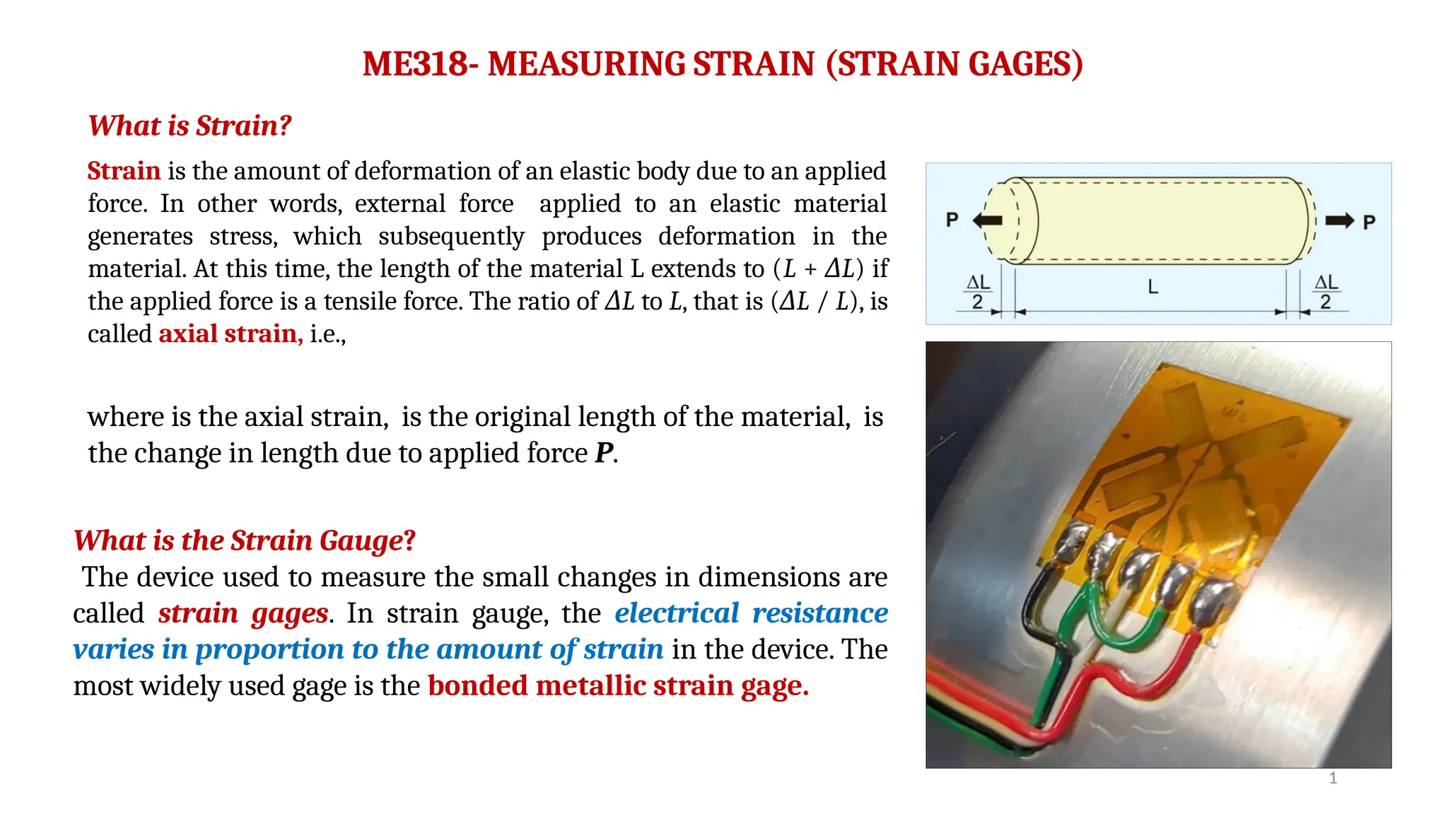
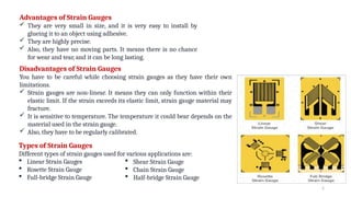
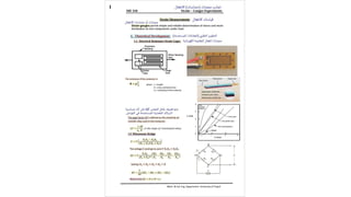
1
ME318- MEASURING STRAIN (STRAIN GAGES)
What is Strain?
Strain is the amount of deformation of an elastic body due to an applied
force. In other words, external force applied to an elastic material
generates stress, which subsequently produces deformation in the
material. At this time, the length of the material L extends to (L + L
Δ ) if
the applied force is a tensile force. The ratio of L
Δ to L, that is ( L
Δ / L), is
called axial strain, i.e.,
where is the axial strain, is the original length of the material, is
the change in length due to applied force P.
What is the Strain Gauge?
The device used to measure the small changes in dimensions are
called strain gages. In strain gauge, the electrical resistance
varies in proportion to the amount of strain in the device. The
most widely used gage is the bonded metallic strain gage.
2
Advantages of Strain Gauges
 They are very small in size, and it is very easy to install by
glueing it to an object using adhesive.
 They are highly precise.
 Also, they have no moving parts. It means there is no chance
for wear and tear, and it can be long lasting.
Disadvantages of Strain Gauges
You have to be careful while choosing strain gauges as they have their own
limitations.
 Strain gauges are non-linear. It means they can only function within their
elastic limit. If the strain exceeds its elastic limit, strain gauge material may
fracture.
 It is sensitive to temperature. The temperature it could bear depends on the
material used in the strain gauge.
 Also, they have to be regularly calibrated.
Types of Strain Gauges
Different types of strain gauges used for various applications are:
 Linear Strain Gauges
 Rosette Strain Gauge
 Full-bridge Strain Gauge
 Shear Strain Gauge
 Chain Strain Gauge
 Half-bridge Strain Gauge
3
Applications of Strain Gauges
 Strain gauges are commonly used to measure the stresses/strains caused
by vertical wheel loads in a railroad track.
 Strain gauges are bonded directly to structural load bearing
components to measure stresses along load paths for wing deflection.
 A simple civil engineering application using strain gauge technology is
to install strain gauges on structural components in a bridge or building
to measure stresses/strains and compare them to analytical models and
stress calculations
 Strain gauges can measure the stresses due to applied torque by a
motor, turbine, or engine to fans, generators, wheels, or propellers.
4
Strain Gauge Principles
The electric resistance of a metal changes proportionally to
the mechanical deformation caused by an external force
applied to the metal. By bonding a thin metal to a measurement
object through a thin electrical insulator, the metal deforms
depending on deformation of the measurement object and its
electric resistance changes. The strain gauge (electrical –
resistance strain gauge) is a sensor to measure the strain by
means of measuring the resistance change.
Strain Gauge Configuration
A strain gauge is constructed by forming a grid made of fine
electric resistance wire or photographically etched metallic
resistance foil on an electrical insulation base (backing), and
attaching gauge leads.
When strain is generated in a measurement object, the strain is transferred to the resistance wire or foil of the strain
gauge via the gauge base (backing). As a result, the wire or foil experiences a resistance change. This change is exactly
proportional to the strain as in the equation below :
(1)
where R is the gauge resistance, ΔR is the resistance change due to strain, and GF is the Gauge Factor or (Sensitivity
Factor) as shown on package.
5
Normally, this resistance change () is very small and requires a
Wheatstone bridge circuit to convert the small resistance change
to a more easily measured voltage change.
The voltage output E of the circuit is given as follows :
(2)
where E is the voltage output, V is the exciting voltage, are fixed
resistances.
The voltage E could go to zero if R1R3 = R2 R4.
The variation of voltage is given as:
Here, if R1 = R2 = R3 = R4 = R, the resistance of the strain gauge
changes to (R+ R
Δ ) due to strain. Thus, the variation of output voltage
( E) due to the strain is given as:
Δ
(3)
From equation (1):
By substituting in equation (3), yields:
(4)
Rearranging equation (4) to get the general equation for the
experimental value of the axial strain as:
6
(5)
When measuring with a strain gauge, it is connected to an instrument called a measuring amplifier. The
amplifier configures a full (four strain gauges) Wheatstone bridge circuit supplied by an exciting input
voltage V.
The voltage change ratio ( E/V)
Δ readings of the Wheatstone bridge circuit are displayed on the digital
display output amplifier, the associated axial strain 𝛆𝒂 is calculated using equation (5). After some slight
change of the left-hand side of equation (5) is depending on the type of loading of the test specimen object
used in the experiment.
5
7
5
5
Experimental Strain Gauges Measurement .pptx

Experimental Strain Gauges Measurement .pptx

  • 1.
    1 ME318- MEASURING STRAIN(STRAIN GAGES) What is Strain? Strain is the amount of deformation of an elastic body due to an applied force. In other words, external force applied to an elastic material generates stress, which subsequently produces deformation in the material. At this time, the length of the material L extends to (L + L Δ ) if the applied force is a tensile force. The ratio of L Δ to L, that is ( L Δ / L), is called axial strain, i.e., where is the axial strain, is the original length of the material, is the change in length due to applied force P. What is the Strain Gauge? The device used to measure the small changes in dimensions are called strain gages. In strain gauge, the electrical resistance varies in proportion to the amount of strain in the device. The most widely used gage is the bonded metallic strain gage.
  • 2.
    2 Advantages of StrainGauges  They are very small in size, and it is very easy to install by glueing it to an object using adhesive.  They are highly precise.  Also, they have no moving parts. It means there is no chance for wear and tear, and it can be long lasting. Disadvantages of Strain Gauges You have to be careful while choosing strain gauges as they have their own limitations.  Strain gauges are non-linear. It means they can only function within their elastic limit. If the strain exceeds its elastic limit, strain gauge material may fracture.  It is sensitive to temperature. The temperature it could bear depends on the material used in the strain gauge.  Also, they have to be regularly calibrated. Types of Strain Gauges Different types of strain gauges used for various applications are:  Linear Strain Gauges  Rosette Strain Gauge  Full-bridge Strain Gauge  Shear Strain Gauge  Chain Strain Gauge  Half-bridge Strain Gauge
  • 3.
    3 Applications of StrainGauges  Strain gauges are commonly used to measure the stresses/strains caused by vertical wheel loads in a railroad track.  Strain gauges are bonded directly to structural load bearing components to measure stresses along load paths for wing deflection.  A simple civil engineering application using strain gauge technology is to install strain gauges on structural components in a bridge or building to measure stresses/strains and compare them to analytical models and stress calculations  Strain gauges can measure the stresses due to applied torque by a motor, turbine, or engine to fans, generators, wheels, or propellers.
  • 4.
    4 Strain Gauge Principles Theelectric resistance of a metal changes proportionally to the mechanical deformation caused by an external force applied to the metal. By bonding a thin metal to a measurement object through a thin electrical insulator, the metal deforms depending on deformation of the measurement object and its electric resistance changes. The strain gauge (electrical – resistance strain gauge) is a sensor to measure the strain by means of measuring the resistance change. Strain Gauge Configuration A strain gauge is constructed by forming a grid made of fine electric resistance wire or photographically etched metallic resistance foil on an electrical insulation base (backing), and attaching gauge leads. When strain is generated in a measurement object, the strain is transferred to the resistance wire or foil of the strain gauge via the gauge base (backing). As a result, the wire or foil experiences a resistance change. This change is exactly proportional to the strain as in the equation below : (1) where R is the gauge resistance, ΔR is the resistance change due to strain, and GF is the Gauge Factor or (Sensitivity Factor) as shown on package.
  • 5.
    5 Normally, this resistancechange () is very small and requires a Wheatstone bridge circuit to convert the small resistance change to a more easily measured voltage change. The voltage output E of the circuit is given as follows : (2) where E is the voltage output, V is the exciting voltage, are fixed resistances. The voltage E could go to zero if R1R3 = R2 R4. The variation of voltage is given as: Here, if R1 = R2 = R3 = R4 = R, the resistance of the strain gauge changes to (R+ R Δ ) due to strain. Thus, the variation of output voltage ( E) due to the strain is given as: Δ (3) From equation (1): By substituting in equation (3), yields: (4) Rearranging equation (4) to get the general equation for the experimental value of the axial strain as:
  • 6.
    6 (5) When measuring witha strain gauge, it is connected to an instrument called a measuring amplifier. The amplifier configures a full (four strain gauges) Wheatstone bridge circuit supplied by an exciting input voltage V. The voltage change ratio ( E/V) Δ readings of the Wheatstone bridge circuit are displayed on the digital display output amplifier, the associated axial strain 𝛆𝒂 is calculated using equation (5). After some slight change of the left-hand side of equation (5) is depending on the type of loading of the test specimen object used in the experiment. 5
  • 7.