Introduction
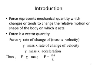
• Force representsmechanical quantity which
changes or tends to change the relative motion or
shape of the body on which it acts.
• Force is a vector quantity.
Force ɣ rate of change of (mass x velocity)
ɣ mass x rate of change of velocity
ɣ mass x acceleration
Thus , F ɣ ma ; F =
2
c
ma
g
3.
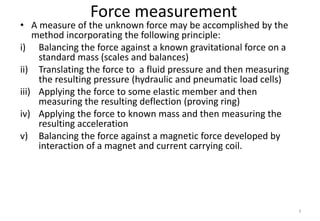
Force measurement
• Ameasure of the unknown force may be accomplished by the
method incorporating the following principle:
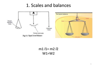
i) Balancing the force against a known gravitational force on a
standard mass (scales and balances)
ii) Translating the force to a fluid pressure and then measuring
the resulting pressure (hydraulic and pneumatic load cells)
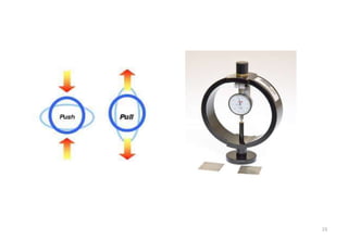
iii) Applying the force to some elastic member and then
measuring the resulting deflection (proving ring)
iv) Applying the force to known mass and then measuring the
resulting acceleration
v) Balancing the force against a magnetic force developed by
interaction of a magnet and current carrying coil.
3
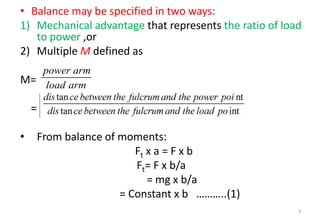
• Balance maybe specified in two ways:
1) Mechanical advantage that represents the ratio of load
to power ,or
2) Multiple M defined as
M=
=
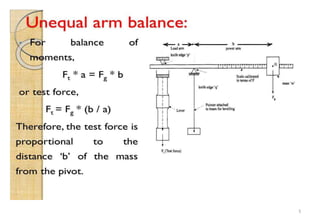
• From balance of moments:
Ft x a = F x b
Ft= F x b/a
= mg x b/a
= Constant x b ………..(1)
6
power arm
load arm
7.
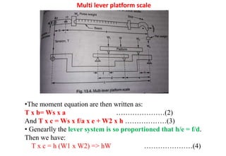
Multi lever platformscale
•The moment equation are then written as:
T x b= Ws x a …………………(2)
And T x c = Ws x f/a x e + W2 x h ………………(3)
• Genearlly the lever system is so proportioned that h/e = f/d.
Then we have:
T x c = h (W1 x W2) => hW …………………(4)
8.
8
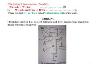
•Eliminating T fromequation (2) and (3);
Ws x a/b = W x h/c ……………………….(5)
Or W= (a/b) x(c/h) Ws => R Ws …………………………….(6)
Where constant R = ac / bh is called Multiplication ratio of the scale.
WORKING
• Pendulum scale (in Fig) is a self balancing and direct reading force measuring
device of multiple lever type.
9.
9
•When the unknownpull P is applied to the load rod, sectors tend to
rotate due to unwinding of the loading tapes and consequently the counetr
weights W swing out.
•Equilibrium conditions are attained when the counter weight effective
moment balances the load moment.
•The resulting linear movement of the equalizer bar is converted to
indicator movement by a rack and pinion arrangement.
•An electrical signal proportional to the force can also be obtained by
incorporating an angular displacement transducer hat would measure the
angular displacement θ.
10.
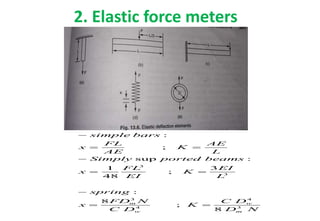
2. Elastic forcemeters
3
3
3 4
4 3
:
;
sup :
1 3
;
48
:
8
;
8
m w
w m
simple bars
FL AE
x K
AE L
Simply ported beams
FL EI
x K
EI L
spring
FD N C D
x K
C D D N
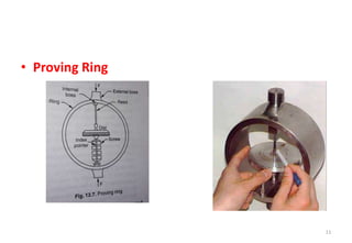
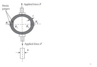
Proving ring
• Theproving ring is a device used to measure force. It consists of an elastic
ring of known diameter with a measuring device located in the center of
the ring.
• They are made of a steel alloy.
• manufactured according to design specifications established in 1946 by
the National Bureau of Standards (NBS).
• Proving rings can be designed to measure either compression or tension
forces.
13.
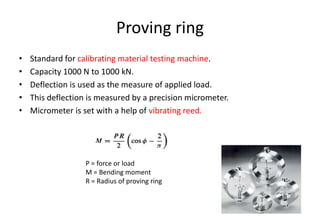
Proving ring
• Standardfor calibrating material testing machine.
• Capacity 1000 N to 1000 kN.
• Deflection is used as the measure of applied load.
• This deflection is measured by a precision micrometer.
• Micrometer is set with a help of vibrating reed.
P = force or load
M = Bending moment
R = Radius of proving ring
14.
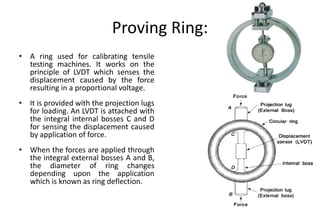
Proving Ring:
• Aring used for calibrating tensile
testing machines. It works on the
principle of LVDT which senses the
displacement caused by the force
resulting in a proportional voltage.
• It is provided with the projection lugs
for loading. An LVDT is attached with
the integral internal bosses C and D
for sensing the displacement caused
by application of force.
• When the forces are applied through
the integral external bosses A and B,
the diameter of ring changes
depending upon the application
which is known as ring deflection.
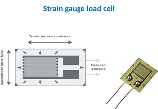
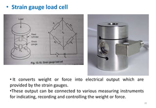
• Strain gaugeload cell
20
• It converts weight or force into electrical output which are
provided by the strain gauges.
•These output can be connected to various measuring instruments
for indicating, recording and controlling the weight or force.
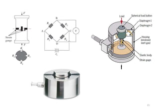
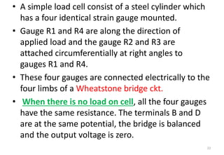
• A simpleload cell consist of a steel cylinder which
has a four identical strain gauge mounted.
• Gauge R1 and R4 are along the direction of
applied load and the gauge R2 and R3 are
attached circumferentially at right angles to
gauges R1 and R4.
• These four gauges are connected electrically to the
four limbs of a Wheatstone bridge ckt.
• When there is no load on cell, all the four gauges
have the same resistance. The terminals B and D
are at the same potential, the bridge is balanced
and the output voltage is zero.
22
23.
• When compressiveload is applied to the unit, the vertical
gauge (R1 and R4) undergo compression and so decrease in
resistance.
• Simultaneously the circumferential gauges R2 and R3
undergo tension and so increase in resistance.
• In poissons arrangement, the positive and negative strains (
and so changes in resistance) are related to each other by
the poissons ratio.
• When strained, the resistance of the various gauges are:
• R1 and R4 = R-dR (compressive) and R2 and R3 = R+μdR
(Tension)
23
; 0
2
s
ab ad o ab ad
V
V V V V V
24.
• Potential atterminal B is,
• Potential at terminal D is,
24
1
1 2
2 1
ab s
s
s
R
V V
R R
R dR
V
R R dR
R dR
V
R dR
3
3 4
2 1
ad s
s
s
s
R
V V
R R
R dR
V
R dR R dR
R dR
V
R dR R dR
R dR
V
R dR
25.
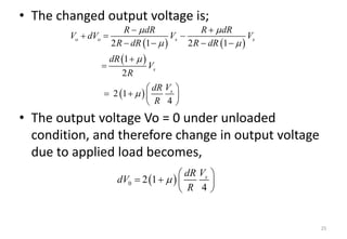
• The changedoutput voltage is;
• The output voltage Vo = 0 under unloaded
condition, and therefore change in output voltage
due to applied load becomes,
25
2 1 2 1
1
2
2 1
4
o o s s
s
s
R dR R dR
V dV V V
R dR R dR
dR
V
R
V
dR
R
0 2 1
4
s
V
dR
dV
R