Download to read offline


![TEMPERATURE MEASURING INSTRUMENTS
Bimetallic strip:
• Let's consider n as the ratio of moduli of elasticity of low to high expansion material, E1 / E2
α1 is a lower coefficient of expansion
α2 is a higher coefficient of expansion
T is operating temperature
T0 is initial bonding temperature
• If the 𝑡1 = 𝑡2 and if the materials are so chosen that 𝐸1 ≅ 𝐸2, then
r = 2t / [3(T – T0) (α2 – α1)]
• Generally, r is very large and the movement of the free tip is very small. However, the tip deflection can be
increased with the choice of materials that give a large value to the factor (α1 − α2).
• Normally the low expansion materials are invar (an iron-nickel alloy containing about 36% nickel) and high
expansion metal is brass. The respective coefficient of expansion for invar and brass are 0.009 × 10⁻⁴ per ℃
and 0.189 × 10⁻⁴ per ℃.](https://image.slidesharecdn.com/ch-5forcetorquepressurestrainandtemperaturemeasurement-210528090055/75/Ch-5-Force-Torque-Pressure-Strain-and-Temperature-measurement-72-2048.jpg)
![TEMPERATURE MEASURING INSTRUMENTS
Bimetallic strip:
• When a bi-metallic strip, in the form of a cantilever, is assumed to bend through a circular arc then,
(r + dr) / r = expanded length of strip having higher expansion coefficient / expanded length of strip having
lower expansion coefficient
= l[1 + α2(T – T0)] / l[1 + α(T1 – T0)]](https://image.slidesharecdn.com/ch-5forcetorquepressurestrainandtemperaturemeasurement-210528090055/75/Ch-5-Force-Torque-Pressure-Strain-and-Temperature-measurement-73-2048.jpg)
![TEMPERATURE MEASURING INSTRUMENTS
Bimetallic strip:
• Simplification gives,
r = dr [1 + α1(T – T0)] / [(α2 – α1)(T1 – T0)]
• With the low expansion metal of invar and the thickness of each metal strip t/2,
α1 ≈ 0 and dr = t/2
• With these stipulations, the equation reduces to,
r = t / [2α2 (T – T0)]
• The movement of the free end of the cantilever in a perpendicular direction from the initial horizontal line is
worked out as follows:
Angular displacement θ = 1/r
Vertical displacement y = OB – OA = r – r cos θ = r(1 - cos θ)](https://image.slidesharecdn.com/ch-5forcetorquepressurestrainandtemperaturemeasurement-210528090055/75/Ch-5-Force-Torque-Pressure-Strain-and-Temperature-measurement-74-2048.jpg)


![TOTAL RADIATION PYROMETER
• The mirror provides a maximum reflection of the incoming radiations onto a thermocouple C which is shielded from
the incoming radiations and carries a blackened copper target disk. Two small semicircular flat mirrors are inclined at
a slight angle from the vertical plane.
• The resulting hole is smaller than the target and this allows radiation from the concave mirror to reach the
thermocouple. The eyepiece and concave mirror are adjusted to focus the radiation from the furnace onto the target.
Small mirrors help in the focusing process.
• These mirrors appear as shown at (i) when the radiation is not focused onto the target and when focusing, is
achieved they appear as at (ii). The object of directing radiations from the measured surface onto the temperature
sensing element can also be achieved by a parabolic reflector [Fig. (b)], or by a lens system [Fig. (c)].](https://image.slidesharecdn.com/ch-5forcetorquepressurestrainandtemperaturemeasurement-210528090055/75/Ch-5-Force-Torque-Pressure-Strain-and-Temperature-measurement-85-2048.jpg)


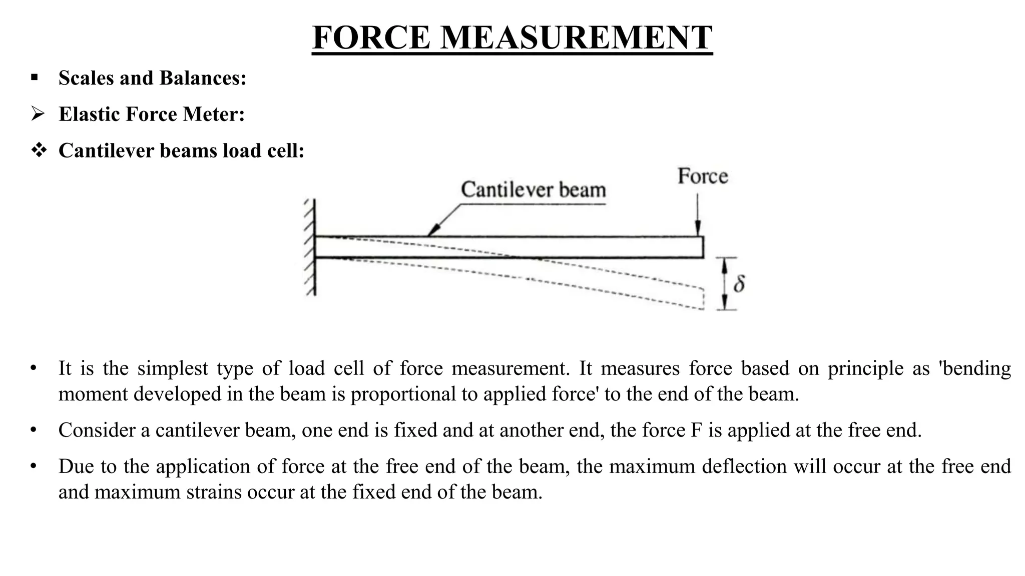
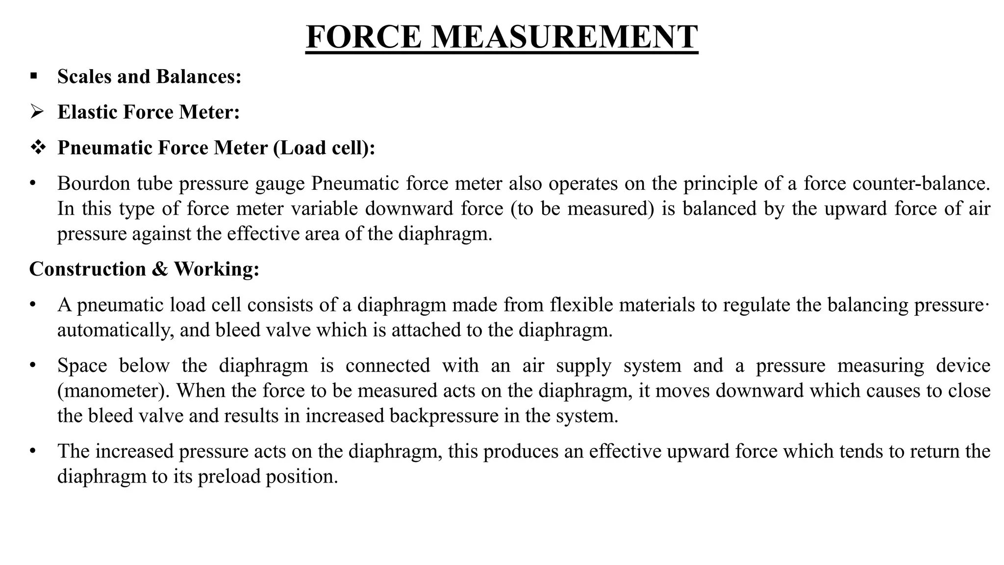
Force can be measured using several methods including scales, balances, elastic elements, and pressure-based techniques. Scales work by balancing the unknown force against a known gravitational force from standard masses. Balances include equal arm, unequal arm, and platform scales. Elastic force meters measure deflection of springs, beams, or rings caused by an applied force. Pressure-based techniques include hydraulic and pneumatic load cells, which translate force into a fluid pressure that is measured.