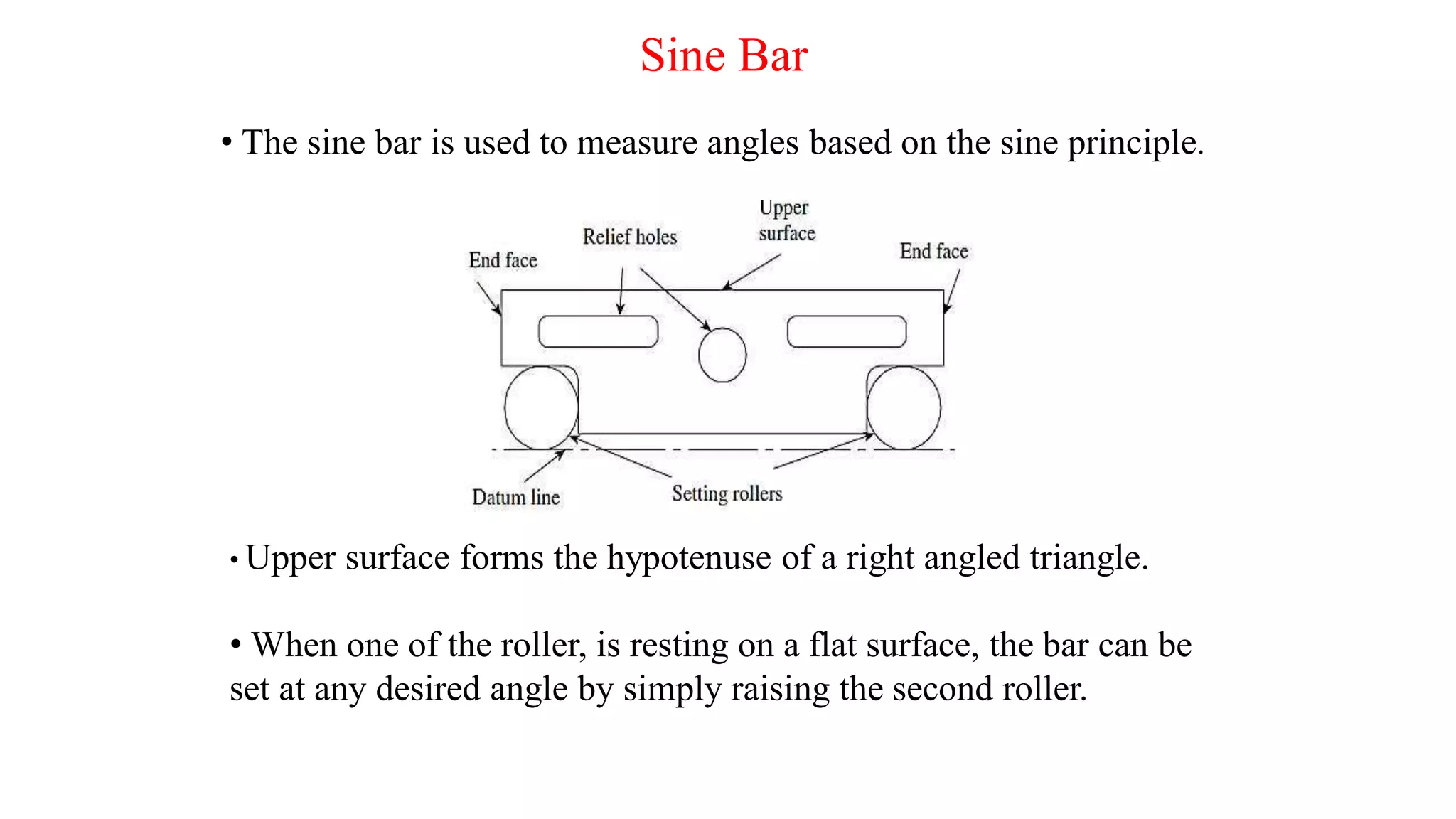
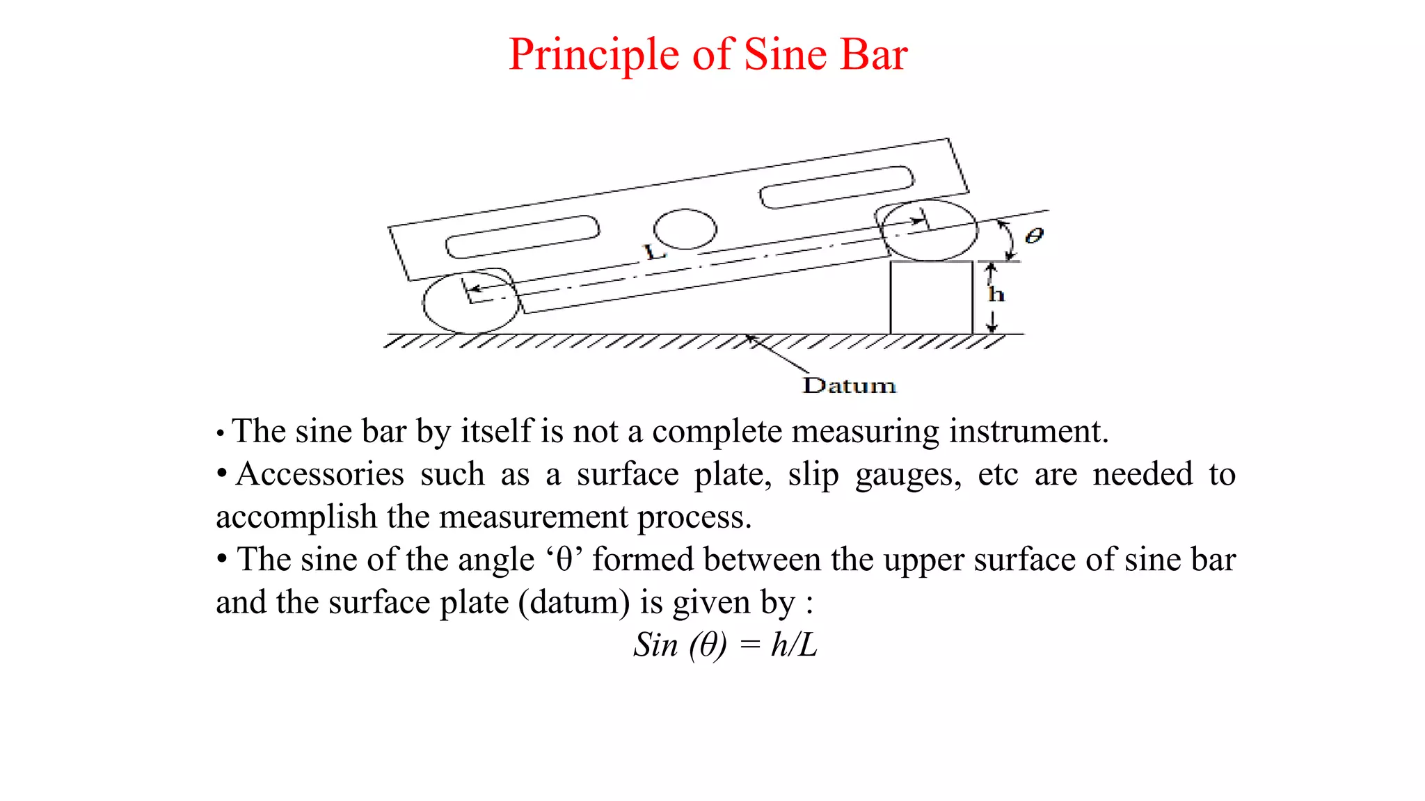
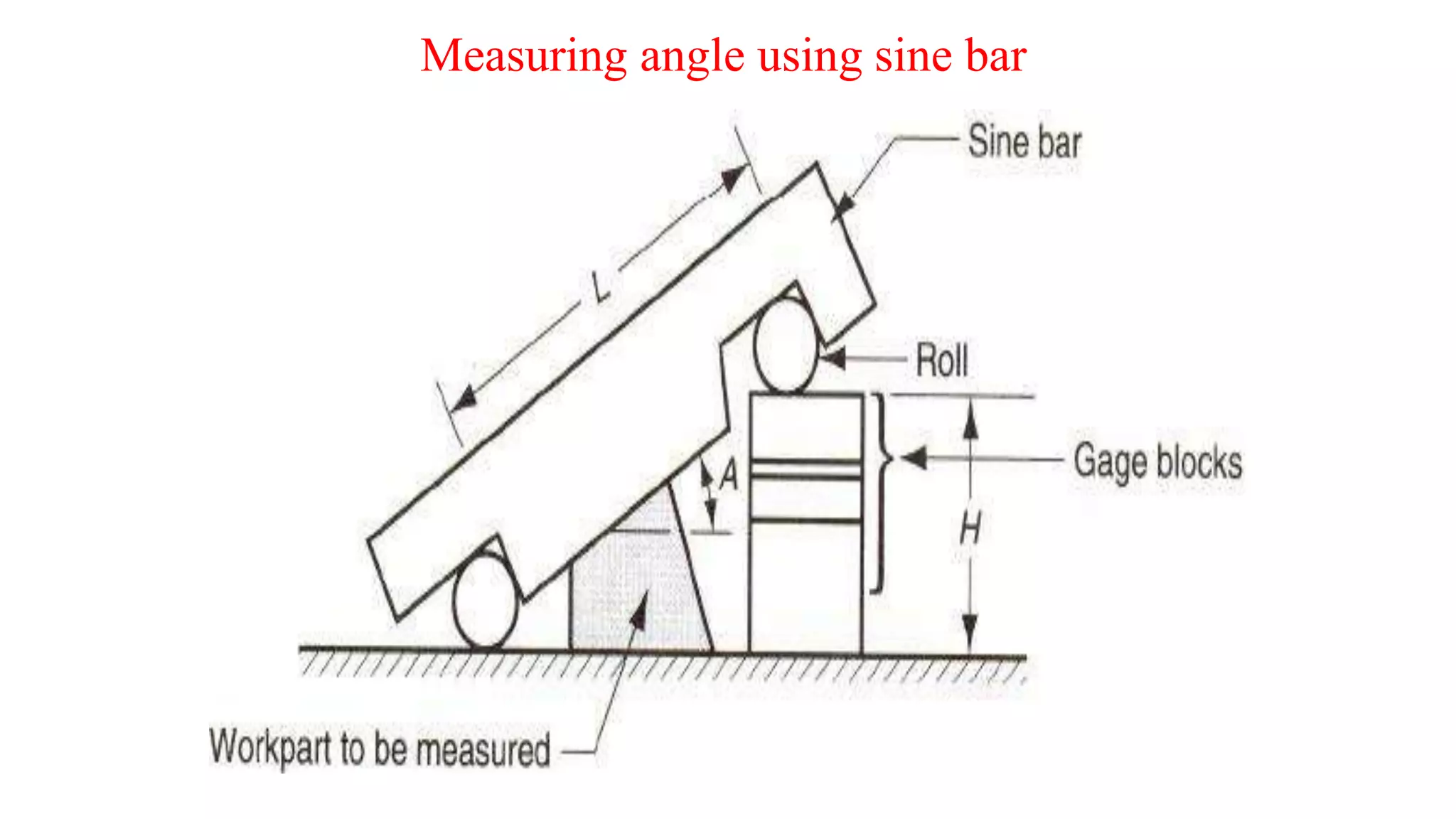
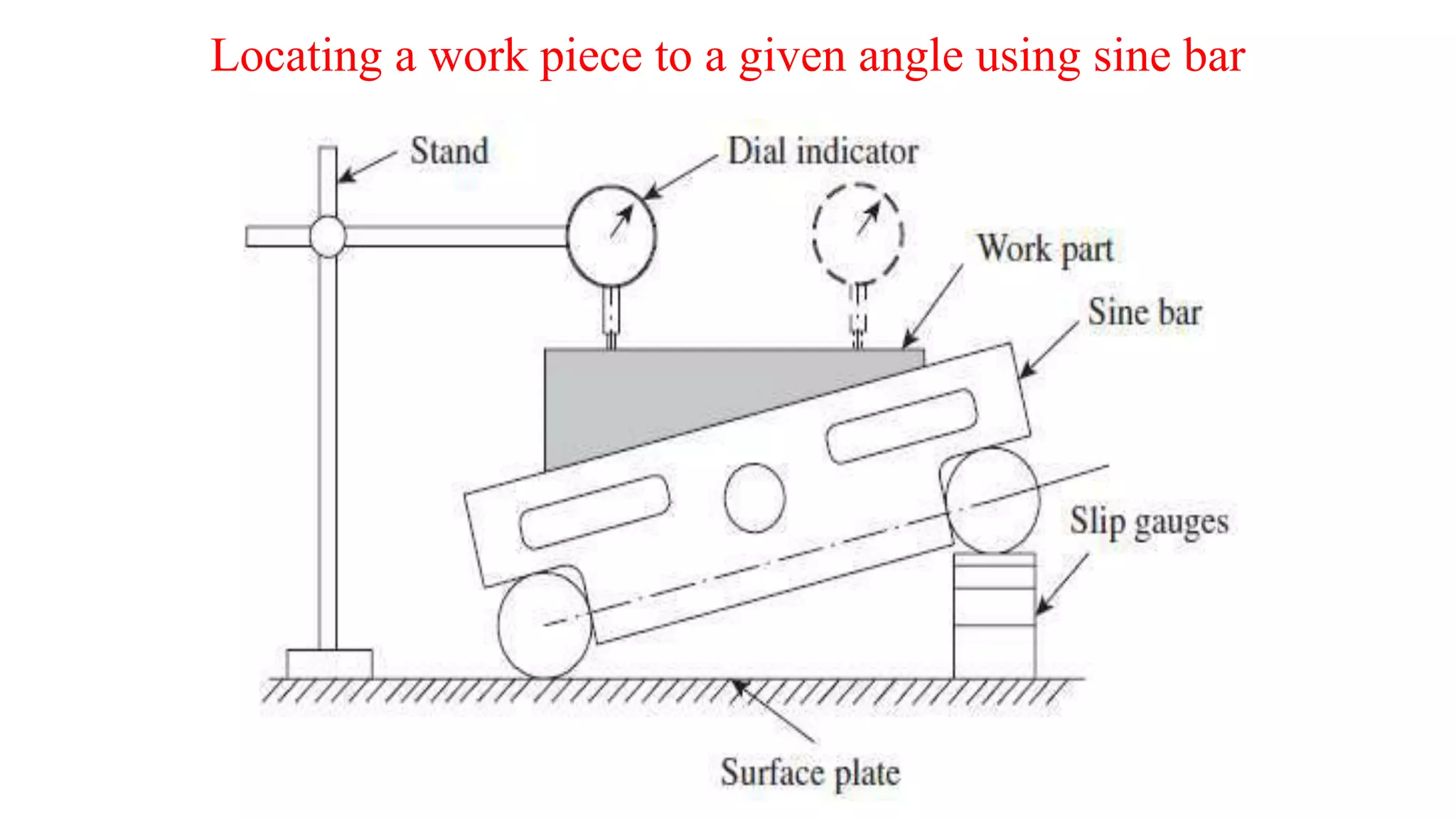
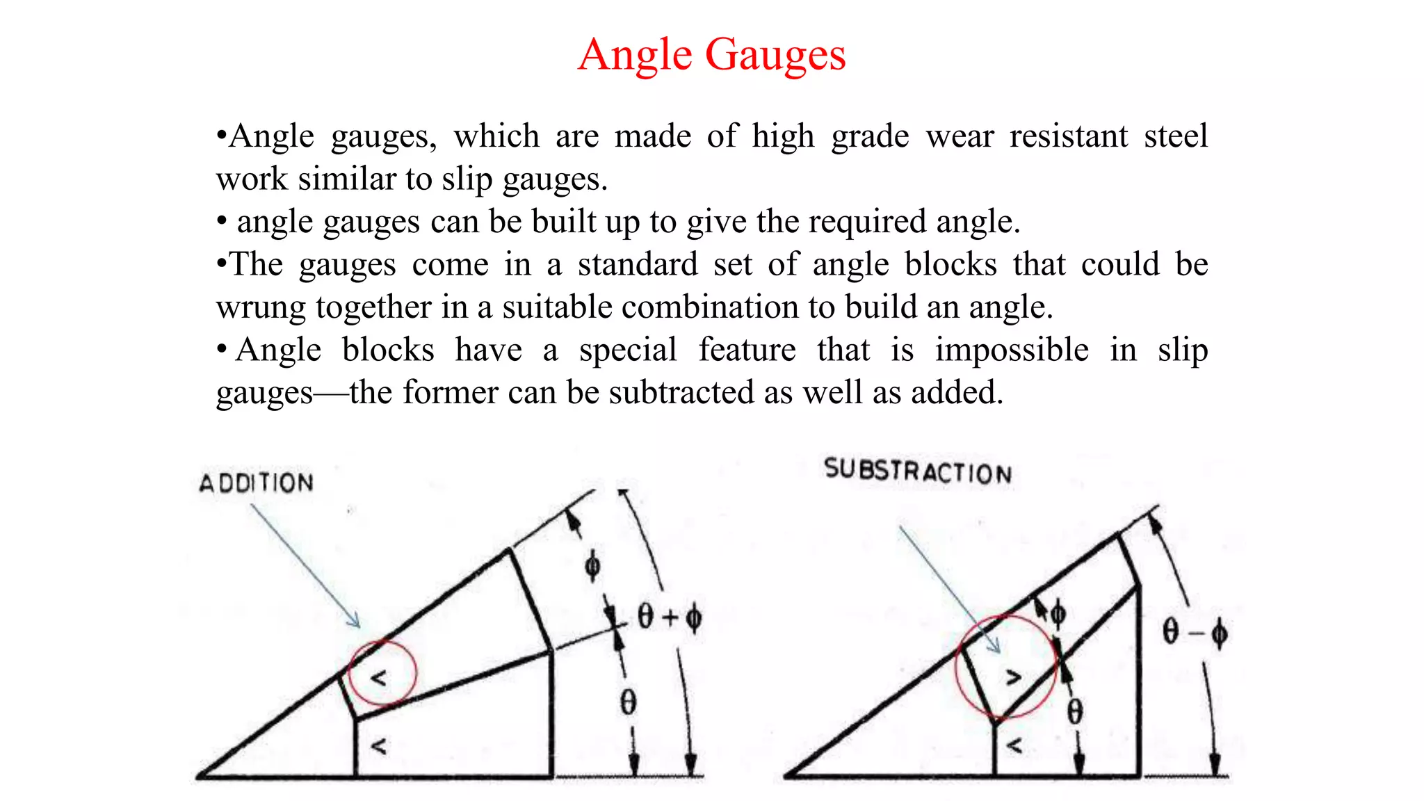
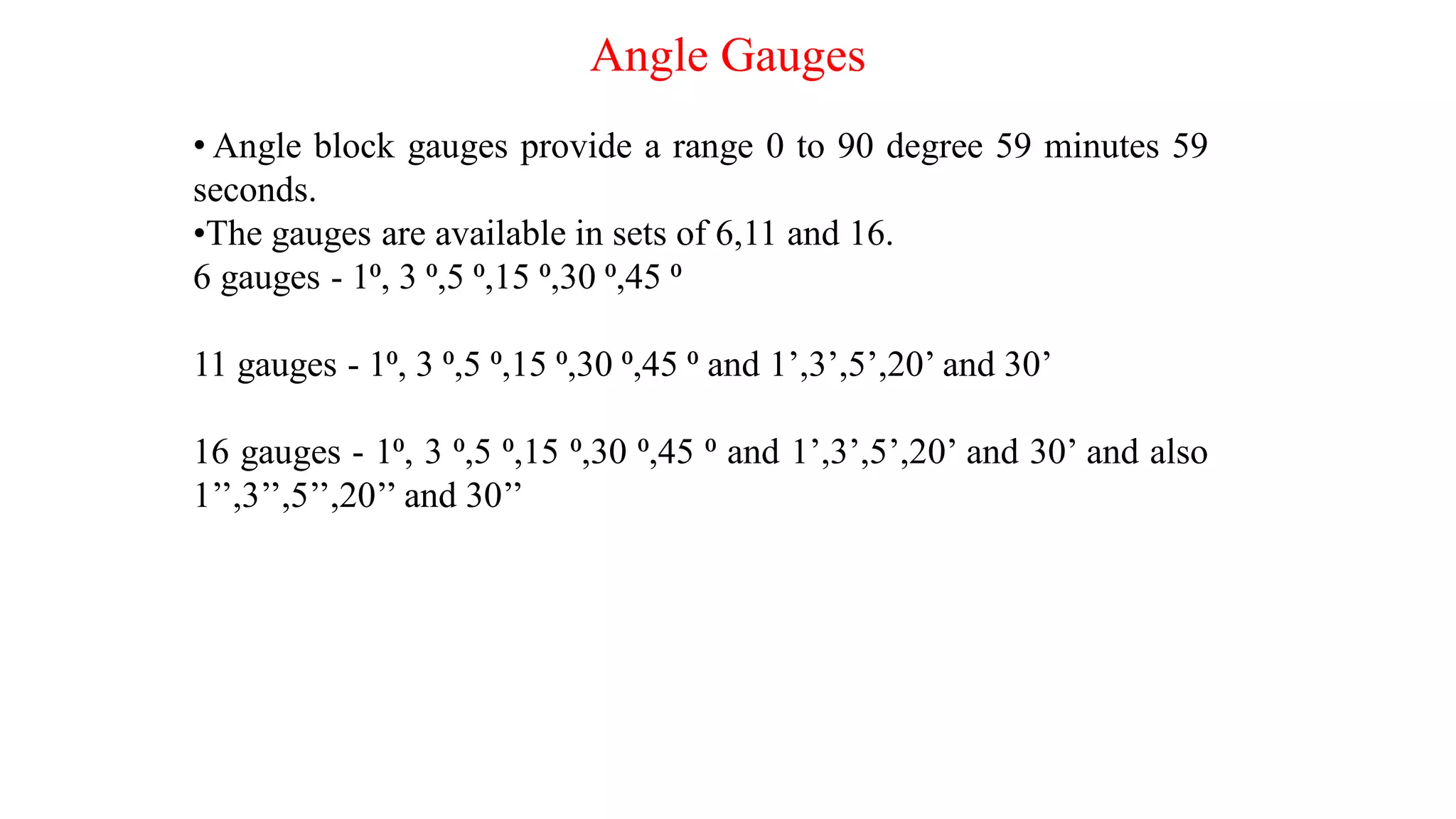
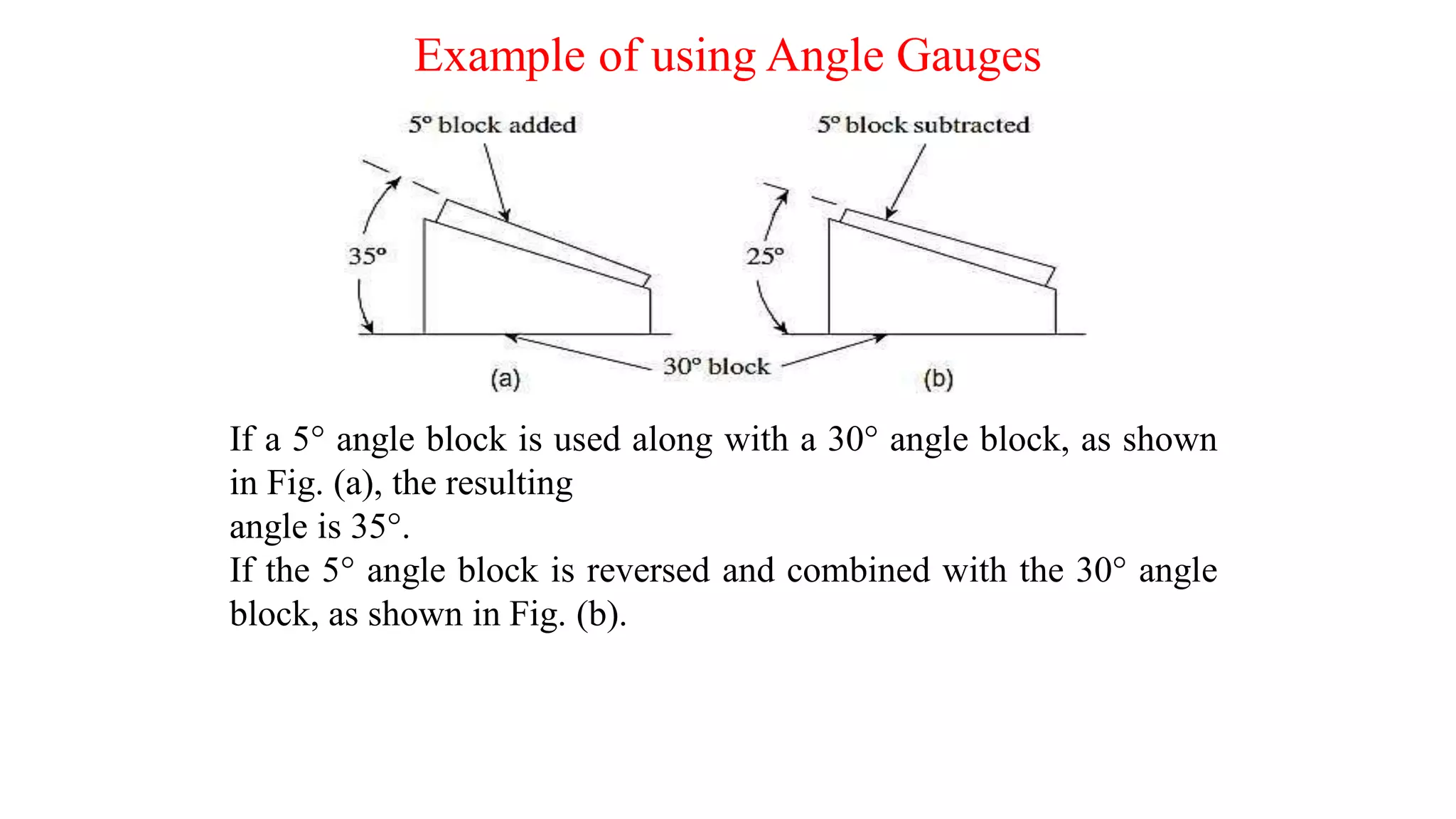
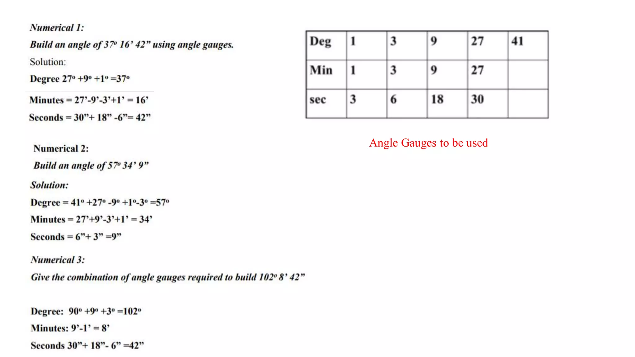
Angular Measurement
Instructor
Mr. Gaurav Bharadwaj
Assistant Prof.
Department of ME
GLA University
Introduction
• Angular measurements are frequently necessary for the manufacture
of interchangeable parts.
• The angle is defined as the opening between two lines which meet at
a point.
• If a circle is divided into 360 equal parts. Each part is called as
degree (0). Each degree is divided in 60 minutes (‘), and each minute is
divided into 60 seconds (“).
• There are many devices used for the angular measurement in the field
of engineering applications.
Protractor
• A simple Protractor is the basic device for measuring angles.
• At best, it can provide least count of one degree for smaller
protractor and half degree for large protractors.
• Like a steel rule, the simple protractor has limited usage in
engineering metrology.
Vernier Bevel Protractor
• Simple protractor has some limitations i.e. it cannot measure in
minutes as its least count is 1 degree or 0.5 degree.
• But, a few additions and a simple mechanism, which can hold a
main scale, a Vernier scale and a rotatable blade, can make it very
versatile.
• A universal bevel protractor is one such instrument, which has a
mechanism that enables easy measurement.
Parts of Vernier Bevel Protractor
1. Stock : – This is one of the contacting surfaces during the
measurement of an angle. Preferably it should be kept in contact with
the datum surface from which the angle is measured.
2. Dial :– The dial is an integrated part of the stock. It is circular in
shape, and the edge is graduated in degrees.
3. Blade:- This is the other surface of the instrument that contacts the
work during measurement. It is fixed to the dial with the help of the
clamping lever. A parallel groove is provided in the centre of the blade
to enable it to be longitudinally positioned whenever necessary.
4. Locking Screws :- Two knurled locking screws are provided, one to
lock the dial to the disc, and the other to lock the blade to the dial.
Least count formula
Least count
• Least Count refers to the smallest distance that can be measured using an
instrument.
• Least Count = Length of 2 MSD – Length of 1 VSD
Where MSD is Main Scale Division and VSD is Vernier Scale Division
respectively
Generally,
12 divisions on Vernier scale = 23 divisions on main scale
1 VSD = 23/12 main scale divisions
Using the formula for Least Count, we get
LC = 2 MSD – 1VSD
= 2 MSD – 23/12MSD
= (24-23)/12 MSD
=1/12 MSD in degree
In min =60/12 = 5 min
Use of Vernier Bevel Protractor
The vernier bevel protractor is used to measure acute angles and
obtuse angles.
Formula for Measurement
Although the least count may vary between different calipers.
The length formula for any caliper is as follows:
Length = MSR + (VSD * LC)
Where MSR = Main Scale Reading
VSD = Vernier Scale Divison
LC = Least Count.
Sine Bar
• The sine bar is used to measure angles based on the sine principle.
• Upper surface forms the hypotenuse of a right angled triangle.
• When one of the roller, is resting on a flat surface, the bar can be
set at any desired angle by simply raising the second roller.
Principle of Sine Bar
• The sine bar by itself is not a complete measuring instrument.
• Accessories such as a surface plate, slip gauges, etc are needed to
accomplish the measurement process.
• The sine of the angle ‘θ’ formed between the upper surface of sine bar
and the surface plate (datum) is given by :
Sin (θ) = h/L
Use of Sine Bar
• To measure the angle of given specimen.
•To locate a work piece on a given angle.
Measuring angle using sine bar
Locating a work piece to a given angle using sine bar
• The top surface is set to the angle, using slip gauges
• A dial gauge is brought in contact with the top surface of the work
part at one end and set to zero.
• The dial indicator is moved to the other end of the work part in a
straight line.
• A zero on the dial indicator indicates that the work surface is perfectly
horizontal / the set angle is the right.
• If the dial indicator shows any deviations, adjustments in the height
of slip gauges is necessary to ensure that the work surface is horizontal.
Requirements of a Sine bar
• Axes of the roller must be parallel and the center distance L must
be known.
• Top surface of the bar must have a high degree of flatness.
• The roller must be of identical diameters.
Limitations of a Sine bar
• Sine bar is used for angle measurement above 45 °.
• For building the slip gauges, there is no scientific approach
available, it is to be built on the trial and error basis and time-
consuming.
• Any unknown projections present in the component will cause to
induce errors in the angle measured.
Why sine bar is not used above 45 ̊?
• The accuracy of the angle set by a sine bar depends on the the errors in
its important dimensions such as error in distance between roller centres,
error in combination of the slip gauges used for setting, error in
parallelism between gauging surface and plane of roller axes etc.
• The slip gauge combination (h) required to set angle (ϴ) is given by,
h = L sin ϴ
The effect of error in spacing of roller centres (dL) or errors in
combination of slip gauges (dh) on angular setting accuracy can be
obtained by partial differentiation of the above equation.
dh/dϴ = (sin ϴ) (dL/dϴ) + L cos ϴ
dh = (sin ϴ) dL + (L cos ϴ) dϴ
dϴ = tan ϴ ((dh/h) - (dL/L))
From the above equation, we can see that, the effect of error in roller
spacing or slip gauge combination is a function of angle ϴ. As the angle
ϴ increases, the error (dϴ) in the angular measurement increases and
above 45
Angle Gauges
•Angle gauges, which are made of high grade wear resistant steel
work similar to slip gauges.
• angle gauges can be built up to give the required angle.
•The gauges come in a standard set of angle blocks that could be
wrung together in a suitable combination to build an angle.
• Angle blocks have a special feature that is impossible in slip
gauges—the former can be subtracted as well as added.
Angle Gauges
• Angle block gauges provide a range 0 to 90 degree 59 minutes 59
seconds.
•The gauges are available in sets of 6,11 and 16.
6 gauges - 1⁰, 3 ⁰,5 ⁰,15 ⁰,30 ⁰,45 ⁰
11 gauges - 1⁰, 3 ⁰,5 ⁰,15 ⁰,30 ⁰,45 ⁰ and 1’,3’,5’,20’ and 30’
16 gauges - 1⁰, 3 ⁰,5 ⁰,15 ⁰,30 ⁰,45 ⁰ and 1’,3’,5’,20’ and 30’ and also
1’’,3’’,5’’,20’’ and 30’’
Example of using Angle Gauges
If a 5° angle block is used along with a 30° angle block, as shown
in Fig. (a), the resulting
angle is 35°.
If the 5° angle block is reversed and combined with the 30° angle
block, as shown in Fig. (b).
Use of Angle Gauges
• Angle gauges are used for measurement and calibration purposes
in tool rooms.
• Used for measuring the angle of a die insert.
• Inspecting compound angles of tools and dies.
• Used in machine shops for setting up a machine.
Angle Gauges to be used

Angular measurement

  • 1.
    Angular Measurement Instructor Mr. GauravBharadwaj Assistant Prof. Department of ME GLA University
  • 2.
    Introduction • Angular measurementsare frequently necessary for the manufacture of interchangeable parts. • The angle is defined as the opening between two lines which meet at a point. • If a circle is divided into 360 equal parts. Each part is called as degree (0). Each degree is divided in 60 minutes (‘), and each minute is divided into 60 seconds (“). • There are many devices used for the angular measurement in the field of engineering applications.
  • 3.
    Protractor • A simpleProtractor is the basic device for measuring angles. • At best, it can provide least count of one degree for smaller protractor and half degree for large protractors. • Like a steel rule, the simple protractor has limited usage in engineering metrology.
  • 4.
    Vernier Bevel Protractor •Simple protractor has some limitations i.e. it cannot measure in minutes as its least count is 1 degree or 0.5 degree. • But, a few additions and a simple mechanism, which can hold a main scale, a Vernier scale and a rotatable blade, can make it very versatile. • A universal bevel protractor is one such instrument, which has a mechanism that enables easy measurement.
  • 5.
    Parts of VernierBevel Protractor
  • 6.
    Parts of VernierBevel Protractor 1. Stock : – This is one of the contacting surfaces during the measurement of an angle. Preferably it should be kept in contact with the datum surface from which the angle is measured. 2. Dial :– The dial is an integrated part of the stock. It is circular in shape, and the edge is graduated in degrees. 3. Blade:- This is the other surface of the instrument that contacts the work during measurement. It is fixed to the dial with the help of the clamping lever. A parallel groove is provided in the centre of the blade to enable it to be longitudinally positioned whenever necessary. 4. Locking Screws :- Two knurled locking screws are provided, one to lock the dial to the disc, and the other to lock the blade to the dial.
  • 7.
    Least count formula Leastcount • Least Count refers to the smallest distance that can be measured using an instrument. • Least Count = Length of 2 MSD – Length of 1 VSD Where MSD is Main Scale Division and VSD is Vernier Scale Division respectively Generally, 12 divisions on Vernier scale = 23 divisions on main scale 1 VSD = 23/12 main scale divisions Using the formula for Least Count, we get LC = 2 MSD – 1VSD = 2 MSD – 23/12MSD = (24-23)/12 MSD =1/12 MSD in degree In min =60/12 = 5 min
  • 8.
    Use of VernierBevel Protractor The vernier bevel protractor is used to measure acute angles and obtuse angles.
  • 9.
    Formula for Measurement Althoughthe least count may vary between different calipers. The length formula for any caliper is as follows: Length = MSR + (VSD * LC) Where MSR = Main Scale Reading VSD = Vernier Scale Divison LC = Least Count.
  • 10.
    Sine Bar • Thesine bar is used to measure angles based on the sine principle. • Upper surface forms the hypotenuse of a right angled triangle. • When one of the roller, is resting on a flat surface, the bar can be set at any desired angle by simply raising the second roller.
  • 11.
    Principle of SineBar • The sine bar by itself is not a complete measuring instrument. • Accessories such as a surface plate, slip gauges, etc are needed to accomplish the measurement process. • The sine of the angle ‘θ’ formed between the upper surface of sine bar and the surface plate (datum) is given by : Sin (θ) = h/L
  • 12.
    Use of SineBar • To measure the angle of given specimen. •To locate a work piece on a given angle.
  • 13.
  • 14.
    Locating a workpiece to a given angle using sine bar
  • 15.
    Locating a workpiece to a given angle using sine bar • The top surface is set to the angle, using slip gauges • A dial gauge is brought in contact with the top surface of the work part at one end and set to zero. • The dial indicator is moved to the other end of the work part in a straight line. • A zero on the dial indicator indicates that the work surface is perfectly horizontal / the set angle is the right. • If the dial indicator shows any deviations, adjustments in the height of slip gauges is necessary to ensure that the work surface is horizontal.
  • 16.
    Requirements of aSine bar • Axes of the roller must be parallel and the center distance L must be known. • Top surface of the bar must have a high degree of flatness. • The roller must be of identical diameters.
  • 17.
    Limitations of aSine bar • Sine bar is used for angle measurement above 45 °. • For building the slip gauges, there is no scientific approach available, it is to be built on the trial and error basis and time- consuming. • Any unknown projections present in the component will cause to induce errors in the angle measured.
  • 18.
    Why sine baris not used above 45 ̊? • The accuracy of the angle set by a sine bar depends on the the errors in its important dimensions such as error in distance between roller centres, error in combination of the slip gauges used for setting, error in parallelism between gauging surface and plane of roller axes etc. • The slip gauge combination (h) required to set angle (ϴ) is given by, h = L sin ϴ The effect of error in spacing of roller centres (dL) or errors in combination of slip gauges (dh) on angular setting accuracy can be obtained by partial differentiation of the above equation. dh/dϴ = (sin ϴ) (dL/dϴ) + L cos ϴ dh = (sin ϴ) dL + (L cos ϴ) dϴ dϴ = tan ϴ ((dh/h) - (dL/L)) From the above equation, we can see that, the effect of error in roller spacing or slip gauge combination is a function of angle ϴ. As the angle ϴ increases, the error (dϴ) in the angular measurement increases and above 45
  • 19.
    Angle Gauges •Angle gauges,which are made of high grade wear resistant steel work similar to slip gauges. • angle gauges can be built up to give the required angle. •The gauges come in a standard set of angle blocks that could be wrung together in a suitable combination to build an angle. • Angle blocks have a special feature that is impossible in slip gauges—the former can be subtracted as well as added.
  • 20.
    Angle Gauges • Angleblock gauges provide a range 0 to 90 degree 59 minutes 59 seconds. •The gauges are available in sets of 6,11 and 16. 6 gauges - 1⁰, 3 ⁰,5 ⁰,15 ⁰,30 ⁰,45 ⁰ 11 gauges - 1⁰, 3 ⁰,5 ⁰,15 ⁰,30 ⁰,45 ⁰ and 1’,3’,5’,20’ and 30’ 16 gauges - 1⁰, 3 ⁰,5 ⁰,15 ⁰,30 ⁰,45 ⁰ and 1’,3’,5’,20’ and 30’ and also 1’’,3’’,5’’,20’’ and 30’’
  • 21.
    Example of usingAngle Gauges If a 5° angle block is used along with a 30° angle block, as shown in Fig. (a), the resulting angle is 35°. If the 5° angle block is reversed and combined with the 30° angle block, as shown in Fig. (b).
  • 22.
    Use of AngleGauges • Angle gauges are used for measurement and calibration purposes in tool rooms. • Used for measuring the angle of a die insert. • Inspecting compound angles of tools and dies. • Used in machine shops for setting up a machine.
  • 23.