Download to read offline


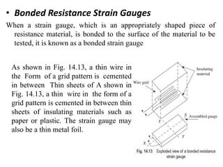


This document discusses different types of strain gauges used to measure strain including mechanical, optical, and electrical strain gauges. Mechanical strain gauges involve direct magnification while optical strain gauges use a combination of mechanical and optical systems. Electrical strain gauges utilize a change in an electrical property like resistance, capacitance, or inductance to measure strain. Resistance strain gauges are most common and can be unbonded, bonded wire or foil types, or semiconductor piezoresistive types. Materials, operation, and applications of each type are described.


