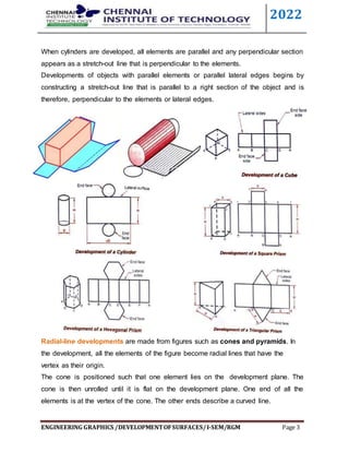
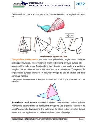
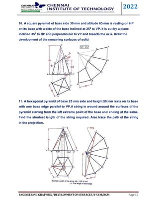
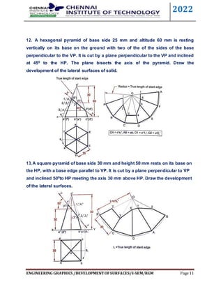
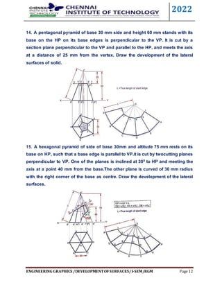
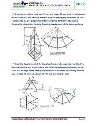
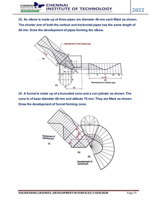
The document discusses the development of surfaces, which is the process of laying out the entire surface of a 3D object onto a 2D plane. It describes various methods for developing different types of surfaces and solids, including parallel line development for prisms and cylinders, radial line development for cones and pyramids, and triangulation for more complex shapes. It then provides examples of developing specific objects like prisms, cylinders, pyramids, and cones.
Projection of solids - ENGINEERING DRAWING/GRAPHICSAbhishek Kandare
Projection of solids
HIS SLIDE CONTAINS WHOLE SYLLABUS OF ENGINEERING DRAWING/GRAPHICS. IT IS THE MOST SIMPLE AND INTERACTIVE WAY TO LEARN ENGINEERING DRAWING.SYLLABUS IS RELATED TO rajiv gandhi proudyogiki vishwavidyalaya / rajiv gandhi TECHNICAL UNIVERSITY ,BHOPAL.
Development of surfaces of solids -ENGINEERING DRAWING - RGPV,BHOPALAbhishek Kandare
Development of surfaces of solids
THIS SLIDE CONTAINS WHOLE SYLLABUS OF ENGINEERING DRAWING/GRAPHICS. IT IS THE MOST SIMPLE AND INTERACTIVE WAY TO LEARN ENGINEERING DRAWING.SYLLABUS IS RELATED TO rajiv gandhi proudyogiki vishwavidyalaya / rajiv gandhi TECHNICAL UNIVERSITY ,BHOPAL.
The document discusses the development of surfaces, which is the unfolding or flattening out of a 3D object onto a 2D plane. Developments show the true size of each surface area and are used in industries like construction to lay out material that is then folded to form the desired object. There are several methods of development including parallel line, radial line, triangulation, and approximate methods for complex surfaces. Examples are provided of developing lateral surfaces of prisms, pyramids, cylinders and cones cut by inclined planes.
introduction of engineering graphics ,projection of points,lines,planes,solids,section of solids,development of surfaces,isometric projection,perspective projection
This document provides information about isometric drawings and projections. It begins by explaining that 3D drawings can be drawn in various ways, including isometrically where the three axes are equally inclined at 120 degrees. It then discusses the construction of isometric scales and various techniques for drawing isometric views of plane figures, solids, and assemblies of objects. Examples are provided to illustrate how to draw isometric views when given orthographic projections of an object. The purpose of isometric drawings is to show the overall size, shape, and appearance of an object prior to production.
The problem provides the top view, front view and position of one end of a line AB. The top view measures 65mm, the front view measures 50mm, and end A is in the horizontal plane and 12mm in front of the vertical plane. To solve the problem:
1) Draw the top view parallel to the XY line since in that case the front view will show the true length.
2) Extend the top view to determine the true length of 75mm.
3) Use trapezoidal method to determine the inclinations of the line with the principal planes as 30 degrees with the horizontal plane and 48 degrees with the vertical plane.
Section of solids - ENGINEERING DRAWING/GRAPHICSAbhishek Kandare
Section of solids
THIS SLIDE CONTAINS WHOLE SYLLABUS OF ENGINEERING DRAWING/GRAPHICS. IT IS THE MOST SIMPLE AND INTERACTIVE WAY TO LEARN ENGINEERING DRAWING.SYLLABUS IS RELATED TO rajiv gandhi proudyogiki vishwavidyalaya / rajiv gandhi TECHNICAL UNIVERSITY ,BHOPAL.
The document provides instructions for projecting plane figures by describing their position relative to the horizontal and vertical planes. It explains that problems will give the plane figure and its inclination to the planes. The document outlines the 3 step process: 1) assume initial position, 2) consider surface inclination, 3) consider side/edge inclination. Examples are given of different inclinations and the steps are applied to sample problems.
1. The document discusses sectioning of solids by cutting planes to understand internal details. It defines types of cutting planes like auxiliary inclined plane (AIP) and auxiliary vertical plane (AVP).
2. An AIP appears as a straight line in the front view and always cuts the front view of a solid. An AVP appears as a straight line in the top view and always cuts the top view of a solid.
3. After launching a section plane in the front or top view, the part towards the observer is assumed to be removed, with the smaller part removed if possible.
This document discusses sections and developments of solids. It begins by defining sectioning a solid as cutting it with an imaginary cutting plane to understand its internal details. Two common section planes are described. Developments of solids are defined as unfolding the hollow object to show its unfolded sheet shape. Engineering applications of developments in sheet metal industries are provided. The document then discusses important terms in sectioning and provides illustrations. It explains developments of different solids and includes nine problems demonstrating sections and developments of prisms, cones, and frustums with step-by-step solutions.
Section of solids, Computer Aided Machine Drawing (CAMD) of VTU Syllabus prepared by Hareesha N Gowda, Asst. Prof, Dayananda Sagar College of Engg, Blore. Please write to hareeshang@gmail.com for suggestions and criticisms.
Download the original presentation for animation and clear understanding. This Presentation describes the concepts of Engineering Drawing of VTU Syllabus. However same can also be used for learning drawing concepts. Please write to me for suggestions and criticisms here: hareeshang@gmail.com or visit this website for more details: www.hareeshang.wikifoundry.com.
The document discusses the projection of solids in engineering graphics. It describes different types of solids including polyhedra like cubes and pyramids. It also covers solids of revolution like cylinders and cones. It explains how to project these solids by assuming their position and drawing front and top views in three steps. Dimensional parameters, inclined positions, and problems involving various solids are also covered.
The document discusses the projection of solids and provides examples of how to project solids in different positions. It describes how to project solids when the axis is perpendicular to or parallel to the horizontal and vertical planes. It also explains how to project solids when the axis is inclined to one of the planes. Examples are provided for projecting prisms, pyramids, cylinders and cones in various positions.
Scales
THIS SLIDE CONTAINS WHOLE SYLLABUS OF ENGINEERING DRAWING/GRAPHICS. IT IS THE MOST SIMPLE AND INTERACTIVE WAY TO LEARN ENGINEERING DRAWING.SYLLABUS IS RELATED TO rajiv gandhi proudyogiki vishwavidyalaya / rajiv gandhi TECHNICAL UNIVERSITY ,BHOPAL.
The document provides information on the projection of plane figures:
1) It explains the basics of plane projection problems, including what is typically given (projections of the plane) and asked for (its position relative to reference planes).
2) Plane figures can have their surface parallel or inclined to the horizontal or vertical planes, and edges parallel or inclined to the other reference plane. The document demonstrates solving problems through 3 steps of initial positioning, surface inclination, and edge inclination.
3) Several example problems are worked through step-by-step to show determining the front, top, and side views of planes in different orientations, such as a pentagon inclined to the horizontal plane and a side to the vertical plane
introduction of engineering graphics ,projection of points,lines,planes,solids,section of solids,development of surfaces,isometric projection,perspective projection
This document discusses the development of surfaces, which is the process of unfolding a 3D object into a flat pattern. It describes various methods for developing different types of surfaces, including parallel line development for prisms and cylinders, radial line development for cones and pyramids, triangulation for complex surfaces, and approximate development for double curved surfaces. The document then provides examples of development problems for prisms, cylinders, pyramids and cones.
The document discusses sections of solids in engineering graphics. It describes how sectioning planes are used to reveal internal details of objects that are otherwise hidden. It defines different types of section planes - principal planes (HP and VP), auxiliary planes (AVP, PP, AIP), and how they appear in different views. Examples are given of different solids cut by various section planes to illustrate how to draw the sectional views and true shape of the cut surface.
This document discusses the projection of planes in engineering graphics. It defines key terms like trace of a plane and horizontal and vertical traces. It describes the different orientations a plane can have in space, such as parallel or perpendicular to the vertical or horizontal planes. It provides examples of how to represent different views of objects in planes using notations. Finally, it includes several example problems demonstrating how to draw the projections of planes in different orientations.
1. The document describes various solids and their classification into two groups - Group A consisting of solids with bases and tops of the same shape, and Group B consisting of solids with bases of some shape and just a point as the top.
2. Dimensional parameters of different solids like cylinders, cones, prisms and pyramids are defined. Positions of solids relative to planes are also described.
3. Three step methods for solving problems involving solids inclined to horizontal and vertical planes are outlined. Various categories of illustrated problems involving different cases are listed.
1. The document provides information on engineering applications of projections of solids, specifically sections of solids, development, and intersections.
2. It instructs the reader to study carefully the illustrations given on the next six pages to understand sectioning a solid, defining section and section planes, and seeing typical section planes and shapes of sections.
3. The document contains sample problems asking the reader to draw various views and shapes based on solids cut by different section planes.
The document discusses the concept of curves of intersection that occur when two solids penetrate or intersect each other. It provides the following key points:
- When two solids intersect, their surfaces meet at a common curve called the curve of intersection. This curve remains common to both solids.
- Curves of intersection show the exact and maximum surface contact between two intersecting solids. They are important when objects need to be joined together with strong, leak-proof joints.
- Several examples of actual intersecting objects from industry are shown, with their curves of intersection indicated.
- Step-by-step solutions are provided for generating curves of intersection between various geometric solids, including cylinders, pr
Projection of Planes- Engineering GraphicsDr Ramesh B T
This document contains 44 problems involving drawing multi-view projections of triangular, rectangular, pentagonal, and hexagonal plane laminae in different orientations relative to reference planes (HP and VP). Each problem provides the shape and dimensions of the lamina, how it is positioned relative to the reference planes, and any other relevant information. The corresponding solutions provide top, front, and sometimes left side view drawings of the lamina(e) based on the given information in each problem.
This document discusses the development of surfaces, which is the process of unfolding 3D objects into 2D patterns. It covers key concepts like parallel-line development for prisms and cylinders, radial-line development for cones and pyramids, and triangulation development for complex surfaces. The document then provides examples of developing various prisms, cylinders, cones and pyramids that are cut or intersected by different planes. Solutions are presented for 14 problems involving developing these different types of objects.
1. A pentagonal prism with a 30mm base side and 50mm axis is resting on its base on the HP. One side of the base is perpendicular to the VP.
2. The prism is cut by a section plane inclined at 45 degrees to the HP, passing through the midpoint of the axis.
3. The development, true shape of the section, and sectional views (FV, TV, and side view) are drawn to show the remaining solid after cutting.
The document discusses the development of lateral surfaces of 3D objects. It defines a development as the unrolled flat shape of a 3D solid that can be folded back into the original shape. There are different methods of developing surfaces - parallel line development for prisms and cylinders, radial line development for pyramids and cones, triangulation development for transition pieces, and approximate development for curved surfaces like spheres. It also discusses sectioning of solids using cutting planes and the development of truncated and frustum shapes. Examples are provided for developing various prisms, pyramids, cylinders and cones.
This document discusses the development of surfaces, which involves unfolding solid objects onto a flat plane. It describes several methods for developing different types of surfaces and solids, including parallel line development for prisms and cylinders, radial line development for cones and pyramids, and triangulation and approximate methods. It provides examples of developing cubes, prisms, pyramids, cones, and truncated solids. Developments allow sheet metal or other surfaces to be cut and folded into desired 3D shapes.
This document discusses the development of surfaces, which involves unfolding solid objects onto a flat plane. It describes several methods for developing different types of surfaces, including parallel line development for prisms and cylinders, radial line development for cones and pyramids, and triangulation and approximate methods. It provides examples of developing cubes, prisms, pyramids and cones. It also gives problems involving developing truncated solids cut by inclined planes.
This document discusses the development of surfaces, which involves unfolding solid objects onto a flat plane. It describes several methods for developing different types of surfaces and solids, including parallel line development for prisms and cylinders, radial line development for cones and pyramids, and triangulation and approximate methods. It provides examples of developing cubes, prisms, pyramids, cones, and truncated solids. Developments allow sheet metal or other surfaces to be cut and folded into desired 3D shapes.
This document contains questions related to engineering graphics concepts including sections of solids, development of surfaces, isometric and perspective projections, and projection of lines and planes. There are a total of 74 questions across 5 units covering topics such as drawing projections, true shapes, developments, and isometric/perspective views of different geometric solids like prisms, pyramids, cones, cylinders when placed in various positions. The questions provide step-by-step instructions to draw the requested views, projections, or developments of the given solids.
1. The document discusses various methods for developing surfaces of 3D objects into 2D patterns, including parallel line development, radial line development, and triangulation development.
2. Parallel line development uses parallel lines and is used for objects with parallel surfaces like prisms and cylinders. Radial line development uses lines radiating from a central point and is used for cones and pyramids.
3. Triangulation development involves subdividing ruled surfaces into triangular areas and is used for polyhedrons and single curved surfaces. Approximate development involves stretching and is used for spheres.
This document discusses different methods for developing the surfaces of 3D objects onto 2D planes. It introduces parallel line development, which is used for objects with parallel edges like prisms and cylinders. Radial line development is used for forms with radiating lines like pyramids and cones. Triangulation development divides warped surfaces into triangles. Approximate development approximates double curved surfaces like spheres by developing zones cut from the surface. The key methods are parallel line, radial line, triangulation, and approximate development.
This document provides information and examples regarding the projection of solids and section of solids in engineering graphics. It includes definitions and problems involving different types of pyramids, prisms, cylinders, cones, and their projections when placed in various positions. It also covers the four types of cutting planes used to obtain different views when sectioning solids, along with examples of each type of section. The document aims to teach concepts related to projecting and sectioning various three-dimensional solids.
This document discusses sectioning of solids in engineering graphics. It defines what a section is and explains different types of section views including full sections, half sections, and removed sections. Various examples of solids cut by planes parallel or perpendicular to standard planes are provided along with instructions on how to draw the sectional views and determine true shapes of cut sections. The document aims to help readers understand how to represent internal structure and cutaways of 3D objects through sectioning.
The document contains a question bank for the course GE 2111 - Engineering Graphics. It includes questions on topics like ellipses, parabolas, hyperbolas, cycloids, involutes, orthographic projections from pictorial views, projection of points and lines, projection of planes and solids, and section of solids. Specifically, it provides 15 questions on ellipses and related curves, 10 questions on orthographic projections from pictures, 12 questions on projection of lines, 15 questions on projection of planes and solids, and 3 questions on section of solids. The questions require skills like construction of curves, drawing projections, finding true lengths and inclinations, and obtaining sections of objects.
1. The document provides information about projection of various solids when their axes are inclined to the principal planes. It discusses different types of solids like prisms, pyramids, cylinders and cones.
2. Step-by-step solutions to 28 problems on projecting such solids in different orientations are presented using methods like rotating object method and auxiliary plane method.
3. The document also covers change of position and auxiliary projection methods for projecting solids with axes inclined to one principal plane and parallel to the other.
introduction of engineering graphics ,projection of points,lines,planes,solids,section of solids,development of surfaces,isometric projection,perspective projection
This document contains 4 sets of questions for an Engineering Drawing exam. Each set contains 8 multi-part questions related to technical drawing topics like orthographic projection, isometric projection, curves of intersection, and perspective projection. The questions provide detailed descriptions of 3D geometric objects and solids, and ask students to draw the front, top, and side views or provide other requested projections based on the given information.
This document contains four sets of questions for an Engineering Drawing examination. Each set contains 8 questions related to topics in engineering drawing like orthographic projections, isometric projections, and perspective projections. The questions involve drawing various geometric shapes and objects like cones, cylinders, prisms and pyramids in different orientations and locations. They also involve cutting objects with planes, finding curves of intersection, and developing surfaces. The questions require applying concepts like projections, penetrations, orientations and visualizing 3D objects from different views.
This document contains an engineering graphics examination paper from November/December 2018. The paper contains 5 questions with multiple parts each related to technical drawing concepts. Question 1 involves drawing the front, top, and side views of an object and sketching the curve traced by the end of an unwinding cable. Question 2 involves finding projections, inclinations, and traces of a line segment. Question 3 involves drawing projections of a cone. Question 4 involves sectioning a pentagonal prism and sketching related views and shapes. Question 5 involves either an isometric view of a combined cone frustum and hexagonal prism structure or a perspective view of a rectangular prism. The paper tests the candidate's ability to apply principles of engineering drawing
This document contains a question bank for the subject Engineering Graphics. It includes questions on constructing various curves like hyperbolas, ellipses, parabolas, cycloids and involutes. It also includes questions on projections of points, lines, plane surfaces and solids. There are questions on sectioning of solids and development of surfaces. The last section includes questions on isometric projections of truncated solids. The questions cover topics like drawing projections, determining true lengths and inclinations, drawing sections, developments and isometric views.
This document contains four engineering drawing examination papers from Jawaharlal Nehru Technological University. Each paper contains 8 multi-part drawing and math problems related to topics like curves, scales, projections, developments, intersections and perspectives. The problems involve geometric shapes like circles, cylinders, prisms, pyramids and their positions in space. Students were asked to complete 5 out of the 8 problems in each paper and show their work to obtain partial marks.
This document discusses development of surfaces and isometric projection. It begins by introducing development of surfaces, including methods of development and developing the surfaces of right solids like cubes, prisms, cylinders, pyramids and cones. It then introduces isometric projection, including isometric axes, lines, planes and scale. It provides examples of developing different objects and drawing isometric views.
Harnessing WebAssembly for Real-time Stateless Streaming PipelinesChristina Lin
Traditionally, dealing with real-time data pipelines has involved significant overhead, even for straightforward tasks like data transformation or masking. However, in this talk, we’ll venture into the dynamic realm of WebAssembly (WASM) and discover how it can revolutionize the creation of stateless streaming pipelines within a Kafka (Redpanda) broker. These pipelines are adept at managing low-latency, high-data-volume scenarios.
International Conference on NLP, Artificial Intelligence, Machine Learning an...gerogepatton
International Conference on NLP, Artificial Intelligence, Machine Learning and Applications (NLAIM 2024) offers a premier global platform for exchanging insights and findings in the theory, methodology, and applications of NLP, Artificial Intelligence, Machine Learning, and their applications. The conference seeks substantial contributions across all key domains of NLP, Artificial Intelligence, Machine Learning, and their practical applications, aiming to foster both theoretical advancements and real-world implementations. With a focus on facilitating collaboration between researchers and practitioners from academia and industry, the conference serves as a nexus for sharing the latest developments in the field.
UNLOCKING HEALTHCARE 4.0: NAVIGATING CRITICAL SUCCESS FACTORS FOR EFFECTIVE I...amsjournal
The Fourth Industrial Revolution is transforming industries, including healthcare, by integrating digital,
physical, and biological technologies. This study examines the integration of 4.0 technologies into
healthcare, identifying success factors and challenges through interviews with 70 stakeholders from 33
countries. Healthcare is evolving significantly, with varied objectives across nations aiming to improve
population health. The study explores stakeholders' perceptions on critical success factors, identifying
challenges such as insufficiently trained personnel, organizational silos, and structural barriers to data
exchange. Facilitators for integration include cost reduction initiatives and interoperability policies.
Technologies like IoT, Big Data, AI, Machine Learning, and robotics enhance diagnostics, treatment
precision, and real-time monitoring, reducing errors and optimizing resource utilization. Automation
improves employee satisfaction and patient care, while Blockchain and telemedicine drive cost reductions.
Successful integration requires skilled professionals and supportive policies, promising efficient resource
use, lower error rates, and accelerated processes, leading to optimized global healthcare outcomes.
Literature Review Basics and Understanding Reference Management.pptxDr Ramhari Poudyal
Three-day training on academic research focuses on analytical tools at United Technical College, supported by the University Grant Commission, Nepal. 24-26 May 2024
ACEP Magazine edition 4th launched on 05.06.2024Rahul
This document provides information about the third edition of the magazine "Sthapatya" published by the Association of Civil Engineers (Practicing) Aurangabad. It includes messages from current and past presidents of ACEP, memories and photos from past ACEP events, information on life time achievement awards given by ACEP, and a technical article on concrete maintenance, repairs and strengthening. The document highlights activities of ACEP and provides a technical educational article for members.
Comparative analysis between traditional aquaponics and reconstructed aquapon...bijceesjournal
The aquaponic system of planting is a method that does not require soil usage. It is a method that only needs water, fish, lava rocks (a substitute for soil), and plants. Aquaponic systems are sustainable and environmentally friendly. Its use not only helps to plant in small spaces but also helps reduce artificial chemical use and minimizes excess water use, as aquaponics consumes 90% less water than soil-based gardening. The study applied a descriptive and experimental design to assess and compare conventional and reconstructed aquaponic methods for reproducing tomatoes. The researchers created an observation checklist to determine the significant factors of the study. The study aims to determine the significant difference between traditional aquaponics and reconstructed aquaponics systems propagating tomatoes in terms of height, weight, girth, and number of fruits. The reconstructed aquaponics system’s higher growth yield results in a much more nourished crop than the traditional aquaponics system. It is superior in its number of fruits, height, weight, and girth measurement. Moreover, the reconstructed aquaponics system is proven to eliminate all the hindrances present in the traditional aquaponics system, which are overcrowding of fish, algae growth, pest problems, contaminated water, and dead fish.
Use PyCharm for remote debugging of WSL on a Windo cf5c162d672e4e58b4dde5d797...shadow0702a
This document serves as a comprehensive step-by-step guide on how to effectively use PyCharm for remote debugging of the Windows Subsystem for Linux (WSL) on a local Windows machine. It meticulously outlines several critical steps in the process, starting with the crucial task of enabling permissions, followed by the installation and configuration of WSL.
The guide then proceeds to explain how to set up the SSH service within the WSL environment, an integral part of the process. Alongside this, it also provides detailed instructions on how to modify the inbound rules of the Windows firewall to facilitate the process, ensuring that there are no connectivity issues that could potentially hinder the debugging process.
The document further emphasizes on the importance of checking the connection between the Windows and WSL environments, providing instructions on how to ensure that the connection is optimal and ready for remote debugging.
It also offers an in-depth guide on how to configure the WSL interpreter and files within the PyCharm environment. This is essential for ensuring that the debugging process is set up correctly and that the program can be run effectively within the WSL terminal.
Additionally, the document provides guidance on how to set up breakpoints for debugging, a fundamental aspect of the debugging process which allows the developer to stop the execution of their code at certain points and inspect their program at those stages.
Finally, the document concludes by providing a link to a reference blog. This blog offers additional information and guidance on configuring the remote Python interpreter in PyCharm, providing the reader with a well-rounded understanding of the process.
IEEE Aerospace and Electronic Systems Society as a Graduate Student Member
DEVELOPMENT OF SURFACES.docx
1. 2022
ENGINEERING GRAPHICS /DEVELOPMENTOFSURFACES/I-SEM/RGM Page 1
DEVELOPMENT OF SURFACES
Introduction
A layout of the complete surface of a three dimensional object on a plane is called the
development of the surface or flat pattern of the object. The development of surfaces
is very important in the fabrication of articles made of sheet metal.
The objects such as containers, boxes, boilers, hoppers, vessels, funnels, trays etc.,
are made of sheet metal by using the principle of development of surfaces.
In making the development of a surface, an opening of the surface should be
determined first.
Every line used in making the development must represent the true length of the line
(edge) on the object.
“The development of surface of an object means the unrolling and unfolding of all
surfaces of the object on a plane.”
“If the surface of a solid is laid out on a plain surface, the shape thus obtained is
called the development of that solid.”
In other words, the development of a solid is the shape of a plain sheet that by proper
folding could be converted into the shape of the concerned solid.
Importance of Development:
Knowledge of development is very useful in sheet metal work, construction of storage
vessels, chemical vessels, boilers, and chimneys. Such vessels are manufactured
from plates that are cut according to these developments and then properly bend into
desired shaped. The joints are then welded or riveted.
Principle of Development:
Every line on the development should show the true length of the corresponding line
on the surface which is developed.
Objective in this topic:
To learn methods of development of surfaces of different solids, their sections and
frustums.
Methods of Development
The method to be followed for making the development of a solid depends upon the
nature of its lateral surfaces. Based on the classification of solids, the following are the
methods of development.
2. 2022
ENGINEERING GRAPHICS /DEVELOPMENTOFSURFACES/I-SEM/RGM Page 2
1. Parallel-line Development
It is used for developing prisms and single curved surfaces like cylinders/prism in
which all the edges / generators of lateral surfaces are parallel to each other.
2. Radial-line Development
It is employed for pyramids and single curved surfaces like cones in which the apex is
taken as centre and the slant edge or generator (which are the true lengths)as radius
for its development.
3. Triangulation method:
This is generally used for polyhedron, single curved surfaces, and warped surfaces.
4. Approximate development:
In this, the shapes obtained are only approximate. After joining, the part is stretched
or distorted to obtain the final shape
Parallel-line developments are made from common solids that are composed of
parallel lateral edges or elements. e.g. Prisms and cylinders
The cylinder is positioned such that one element lies on the development plane. The
cylinder is then unrolled until it is flat on the development plane. The base and top of
the cylinder are circles, with a circumference equal to the length of the development.
All elements of the cylinder are parallel and are perpendicular to the base and the top.
3. 2022
ENGINEERING GRAPHICS /DEVELOPMENTOFSURFACES/I-SEM/RGM Page 3
When cylinders are developed, all elements are parallel and any perpendicular section
appears as a stretch-out line that is perpendicular to the elements.
Developments of objects with parallel elements or parallel lateral edges begins by
constructing a stretch-out line that is parallel to a right section of the object and is
therefore, perpendicular to the elements or lateral edges.
Radial-line developments are made from figures such as cones and pyramids. In
the development, all the elements of the figure become radial lines that have the
vertex as their origin.
The cone is positioned such that one element lies on the development plane. The
cone is then unrolled until it is flat on the development plane. One end of all the
elements is at the vertex of the cone. The other ends describe a curved line.
4. 2022
ENGINEERING GRAPHICS /DEVELOPMENTOFSURFACES/I-SEM/RGM Page 4
The base of the cone is a circle, with a circumference equal to the length of the curved
line.
Triangulation developments are made from polyhedrons, single curved surfaces,
and wrapped surfaces. The development involve subdividing any ruled surface into
a series of triangular areas. If each side of every triangle is true length, any number of
triangles can be connected into a flat plane to form a development Triangulation for
single curved surfaces increases in accuracy through the use of smaller and more
numerous triangles.
Triangulation developments of wrapped surfaces produces only approximate of those
surfaces.
Approximate developments are used for double curved surfaces, such as spheres.
Approximate developments are constructed through the use of conical sections of the
object.Approximate developments the material of the object is then stretched through
various machine applications to produce the development of the object.
5. 2022
ENGINEERING GRAPHICS /DEVELOPMENTOFSURFACES/I-SEM/RGM Page 5
DEVELOPMENT OF SURFACES – PRISM PROBLEMS
1. A Square prism of base side 40 mm and axis length 50 mm is resting on HP
on one of its base with a side of base inclined at 350 to VP. It is cut by a plane
inclined at 300 to HP and perpendicular to VP and is bisecting the axis. Draw the
development of the remaining portion of the prism.
6. 2022
ENGINEERING GRAPHICS /DEVELOPMENTOFSURFACES/I-SEM/RGM Page 6
2. A pentagonal prism of base side 25 mm and height 55 mm is cut by a plane
perpendicular to VP and 300 to HP and passing through the axis 30 mm above
the base, draw the lateral surfaces development in the lower portion of the solid.
3. A pentagonal prism of base side 25 mm and height 60 mm is resting on the
ground with one of its base edge parallel to VP .Find graphically the shortest
distance of the string which connect one end of the lateral edge with the other
end of the same edge, covering all the lateral surfaces of the solid. Also trace
the points on the development.
7. 2022
ENGINEERING GRAPHICS /DEVELOPMENTOFSURFACES/I-SEM/RGM Page 7
4. A hexagonal prism of base side 30 mm and height 60 mm is resting on the
ground with one of its vertical faces perpendicular to VP .it is cut by a plane
inclined at 500 to HP and perpendicular to VP and meets the axis of the prism at
a distance of 10 mm from the top end. Draw the development of the lateral
surfaces
DEVELOPMENT OF SURFACES – CYLINDER
5. Draw the development of the lateral surfaces of the lower portion of a cylinder
of diameter 45 mm and height 60 mm when sectioned by a plane inclined at
400to HP and perpendicular to VP and bisecting the axis.
8. 2022
ENGINEERING GRAPHICS /DEVELOPMENTOFSURFACES/I-SEM/RGM Page 8
6. A cylinder of diameter 50 mm and axis height 65 mm is cut by a plane inclined
at 600 to the HP and bisecting the axis. Draw the development of the lateral
surfaces
7. A cylinder of diameter 40 mm and axis height 75 mm is cut by a plane
perpendicular to VP inclined at 550 to HP meeting the axis at the top face. Draw
the development of the lateral surfaces of solid.
9. 2022
ENGINEERING GRAPHICS /DEVELOPMENTOFSURFACES/I-SEM/RGM Page 9
DEVELOPMENT OF SURFACES – PYRAMIDS
8. A pentagonal pyramid of base 25 mm side and height 65 mm stands with its
base on the HP such that one of its base edges is parallel to the VP. It is cut by a
section plane perpendicular to the VP and inclined at 300 to the HP, bisecting
the axis. Draw the development of the lateral surfaces of solid.
9.A pentagonal pyramid of base 25 mm side and height 60 mm lying on the HP
on its base such that one of its base edges is parallel to and far away from the
VP. It is cut by a section plane one is perpendicular to the VP and inclined at 400
to the HP, and meeting the axis at 14 mm from the base the other plane is
parallel to HP and perpendicular to VP meeting the axis distance of 28 mm from
the base. Draw the development of the lateral surfaces of solid.
10. 2022
ENGINEERING GRAPHICS /DEVELOPMENTOFSURFACES/I-SEM/RGM Page 10
10. A square pyramid of base side 30 mm and altitude 65 mm is resting on HP
on its base with a side of the base inclined at 250 to VP. It is cut by a plane
inclined 350 to HP and perpendicular to VP and bisects the axis. Draw the
development of the remaining surfaces of solid
11. A hexagonal pyramid of base 25 mm side and height 50 mm rests on its base
with one base edge parallel to VP.A string is wound around the surfaces of the
pyramid starting from the left extreme point of the base and ending at the same.
Find the shortest length of the string required. Also trace the path of the string
in the projection.
11. 2022
ENGINEERING GRAPHICS /DEVELOPMENTOFSURFACES/I-SEM/RGM Page 11
12. A hexagonal pyramid of base side 25 mm and altitude 60 mm is resting
vertically on its base on the ground with two of the of the sides of the base
perpendicular to the VP. It is cut by a plane perpendicular to the VP and inclined
at 450 to the HP. The plane bisects the axis of the pyramid. Draw the
development of the lateral surfaces of solid.
13.A square pyramid of base side 30 mm and height 50 mm rests on its base on
the HP, with a base edge parallel to VP. It is cut by a plane perpendicular to VP
and inclined 500to HP meeting the axis 30 mm above HP. Draw the development
of the lateral surfaces.
12. 2022
ENGINEERING GRAPHICS /DEVELOPMENTOFSURFACES/I-SEM/RGM Page 12
14. A pentagonal pyramid of base 30 mm side and height 60 mm stands with its
base on the HP on its base edges is perpendicular to the VP. It is cut by a
section plane perpendicular to the VP and parallel to the HP, and meets the axis
at a distance of 25 mm from the vertex. Draw the development of the lateral
surfaces of solid.
15. A hexagonal pyramid of side of base 30mm and altitude 75 mm rests on its
base on HP, such that a base edge is parallel to VP.it is cut by twocutting planes
perpendicular to VP. One of the planes is inclined at 300 to HP and meeting the
axis at a point 40 mm from the base.The other plane is curved of 30 mm radius
with the right corner of the base as centre. Draw the development of the lateral
surfaces.
13. 2022
ENGINEERING GRAPHICS /DEVELOPMENTOFSURFACES/I-SEM/RGM Page 13
16. A square pyramid of base side 35 mm and height 70 mm rests on its base on
the HP, such that two adjacent sides of the base are equally inclined to VP. It is
sectioned by a plane perpendicular to VP, inclined 300to HP and passing
through the midpoint of the axis. Draw the development of the lateral surfaces.
17. Draw the development of the lateral surfaces of a hexagonal pyramid with a
40 mm base side and a 60 mm long axis ,which is resting on the base in the HP
such that an edge of the base is perpendicular to VP when an auxiliary inclined
plane whose VT makes on angle 600 HP and bisecting the axis.
14. 2022
ENGINEERING GRAPHICS /DEVELOPMENTOFSURFACES/I-SEM/RGM Page 14
DEVELOPMENT OF SURFACES – CONE
18. A cone of base side 60mm and height 70 mm rests on its base on the HP, It
is sectioned by a plane perpendicular both HP and VP, and 10 mm away from
the axis. Draw the development of the lateral surfaces.
19. A cone of base side 50 mm and height 65 mm rests on its base on the HP, It
is sectioned by a plane perpendicular VP and inclined at 300 to HP bisect the
axis of the cone. Draw the development of the lateral surface.
15. 2022
ENGINEERING GRAPHICS /DEVELOPMENTOFSURFACES/I-SEM/RGM Page 15
20.A right circular cone of diameter 50 mm axis height 60 mm is string on the
ground with its base. Calculate the shortest length of a string required to wound
round the lateral surface of the solid starting from one extreme point and ending
at the same point. Also trace the points on to the projections.
21. A cone of base side 50 mm and height 75 mm rests on its base on the HP, It
is sectioned by a plane perpendicular VP and parallel to HP at a distance 20 mm
from the vertex. It is also cut by a plane inclined at 400to the base and meeting
the axis at a point 22 mm above the base. Draw the development of the lateral
surface.
16. 2022
ENGINEERING GRAPHICS /DEVELOPMENTOFSURFACES/I-SEM/RGM Page 16
22.A cone of base side 45 mm and height 70 mm rests on its base on the HP, It is
sectioned by a plane perpendicular VP 300to HP and bisecting the axis. Draw the
development of the lateral surfaces
23. A cone of base side 50 mm and height 60 mm rests on its base on the HP, It
is sectioned by a plane perpendicular VP ,parallel to one of the generators and
passing through a point on the axis at a distance of 22 mm from the apex. Draw
the development of the lateral surfaces
18. 2022
ENGINEERING GRAPHICS /DEVELOPMENTOFSURFACES/I-SEM/RGM Page 18
26. Draw the development of the three pipes forming a Y shape as shown. All the pipes
are diameters of 40 mm. The max. Height of the vertical pipe is 50 mm. The angle
between the axes of the inclined pipes is 800.
27. An offset fitting is made up of three pipes of diameter 40 mm each. The total length
of the fitting is 90 mm and the offset is 55 mm. Draw the lateral surface of the pipes.
19. ENGINEERING GRAPHICS /DEVELOPMENTOFSURFACES/I-SEM/RGM Page 19
2022
28. An elbow is made up of three pipes are diameter 40 mm each fitted as shown.
The shorter arm of both the vertical and horizontal pipes has the same length of
20 mm. Draw the development of pipes forming the elbow.
29. A funnel is made up of a truncated cone and a cut cylinder as shown. The
cone is of base diameter 60 mm and altitude 70 mm. They are fitted as shown.
Draw the development of funnel forming cone.