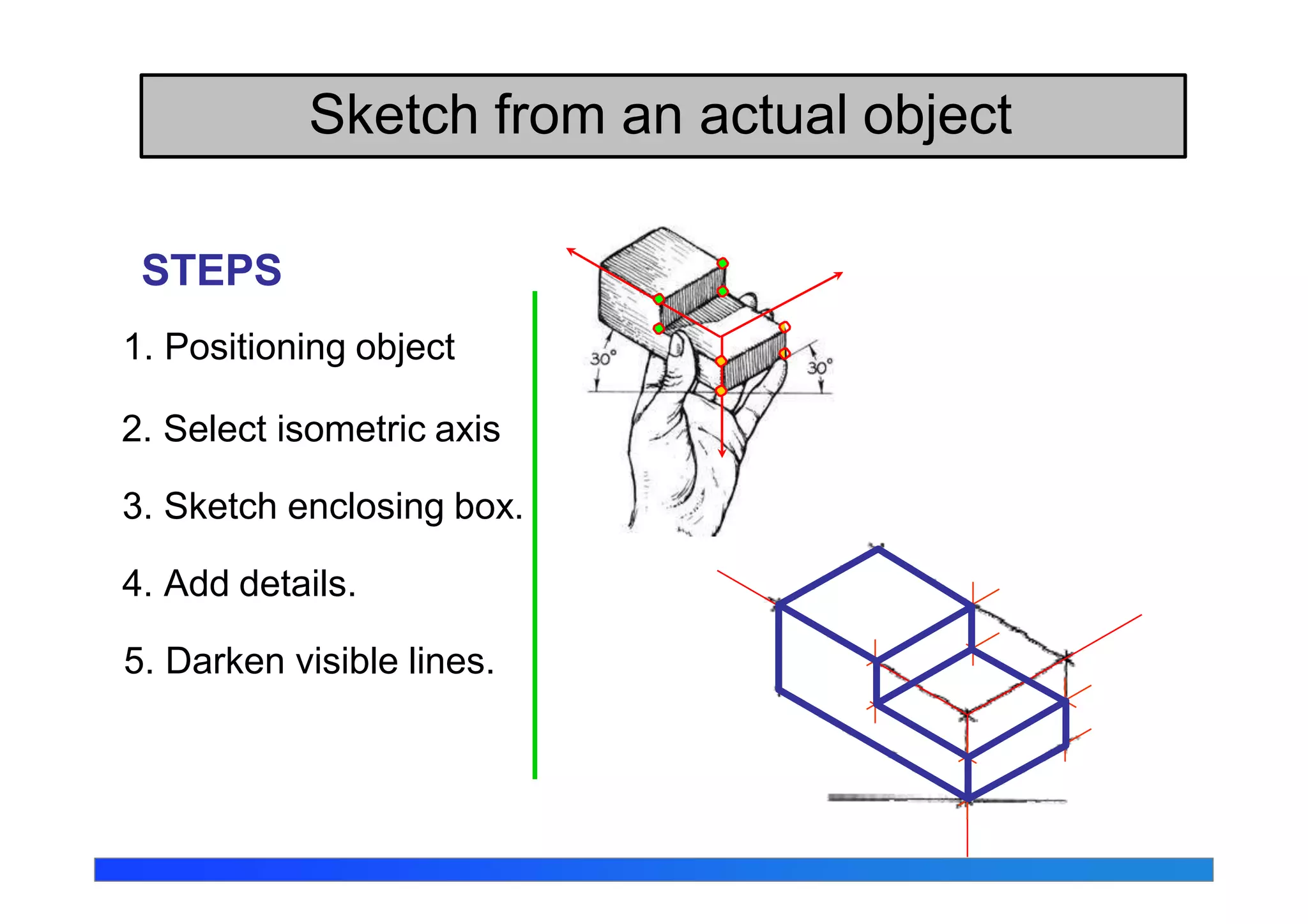
Civil Engineering Drawing
Session 2015
C
A
D
B
Axonometric Projection
Type of axonometric drawing
a
b c
2. Dimetric Two angles are equal
b
a
c
3. Trimetric None of angles are
equal.
a
b c
1. Isometric All angles are equal
A
B
C
D
Axonometric axis
Sana Khan
UG-CE-2012 24/12/12
Axonometric axis
Axonometric axis
Isometric Projections
• It is a type of pictorial projection in
which three dimensions of a solid
are clearly shown. The actual
dimensions of the solids can also
be measured directly from such
projections
• If a cube is placed on one of its
corners on the ground with one of
the solid’s diagonal perpendicular
to the VP, the front view is the
isometric projection of the cube.
• All the faces of the cube are equally inclined to
the VP and hence, they are seen as similar
and equal rhombus instead of squares.
• Three lines, DA, DC and DF meeting at D,
represent the three edges of the solid. Right
angles are also equally inclined to the VP and
are, therefore equally foreshortened. They
make equal angles of 120 degrees with each
other. The line DF being vertical, the other two
lines DA and DC make 30 degree angles each
with the horizontal
• All the remaining lines representing the edges
of the cube are parallel to one or the other of
the above three lines and are also equally
foreshortened
• The diagonal AC of the top face is parallel to
the VP and hence, retains its actual length
FIG. 1
Isometric Axes, Lines and Planes
DA, DC and DF lines, meeting at
point D and subtending 120 degree
angles with each other are termed
as Isometric axes. All the lines
parallel to these axes are known as
isometric lines. The planes
representing the faces of the cubes
shown in Fig. 1 as well as other
planes parallel to these planes are
called isometric planes. In Fig.1.
EF, FG, FA, GC are examples of
Isometric lines, where faces ABCD,
ADFE, DFGC etc. are the examples
of Isometric planes
FIG. 1
Isometric scale
• As all the edges of the cube shown
in Fig. 1 have been equally
foreshortened the square faces
looks like rhombus. The rhombus
(i.e. ABCD) AC diagonal maintains
the true length of the diagonal
• Construct a square AQCP on
diagonal AC. AQ and AP are the
true lengths of the sides of the
square face, AD and AB are the
isometric lengths of sides AC and
AQ respectively FIG. 1
Isometric scale……contd
FIG. 1
UG-C
Isometric scale
• Thus isometric projection is reduced in the ratio ✓2:✓3
i.e. isometric lengths are 0.815 of the true length.
• Thus while drawing an isometric projection; it is essential
to convert true lengths into isometric lengths for
measuring and marking the sizes. This can easily be
done by constructing and making use of an isometric
scale.
Isometric scale
Draw a horizontal line BC of any length [fig. 2]. At the end B, draw
lines BA and BP making angles of 30 degree and 45 degree
respectively with BC. On line BP, mark divisions of true length. From
each division point on BP, draw vertical lines on BC. The vertical
lines will cut also cut the lines BA. The points thus obtained on line
BA give lengths on isometric scale.
Isometric scale….contd
The same scale can drawn with divisions of natural scale on
horizontal line BP [fig. 3]. From the ends B and P, draw lines BA and
PA making 15 degree and 45 degree angles with BP respectively,
and intersecting each other at point A. From division points of true
length on BP, draw lines parallel to PA and meeting BA at respective
points. The division along BA give dimensions on Isometric scales.
UG-CE-2014555 1
Isometric Drawing or Isometric View
• If the foreshortening of the isometric
lines in an isometric projection is
disregarded and instead, the true
lengths are marked, the view obtained
will be exactly of the same shape but
larger in proportion (about 22.5%) than
that obtained by the use of isometric
scale.
• Due to the ease in construction and the
advantage of measuring the dimensions
directly from the drawing, it has become
a general practice to use the true scale
instead of the isometric scale.
• To avoid confusion, the view drawn with
the true scale is called isometric drawing
or isometric view, whilethat drawn with
the use of isometric scale is called
isometric projection.
Isometric Drawing or Isometric View
• in isometric view of any
rectangular solid resting on a
face on the ground, each
horizontal face will have its
sides parallel to the two sloping
axes.
Isometric Drawing or Isometric View
• Each vertical face will have its sides parallel to
the vertical axis and the other sides parallel to
one of the sloping axes.
• In other words, the vertical edgesi.e. shown
by vertical lines, while the horizontal edges are
represented by lines,making 30 degree
angles with the horizontal. These lines are
very conveniently drawn with the T-square and
a 30-60 degreeset square
Isometric sketch
Isometric sketch is an isometric view that is drawn
in full size.
Isometric projection
(True projection)
Isometric drawing
(Full size)
Forshorten
Full scale
Orientation of Isometric Axes
Isometric axes can be arbitrarily oriented to create
different views of a single object.
Regular
isometric
Reverse axis
isometric
Long axis
isometric
View point is looking
down on the top of
the object.
View point is looking
up on the bottom of
the object.
View point is looking
from the right (or left)
of the object.
UG-CE-2012 24/12/12 Sana Khan
Isometric
Sketching
1. Place the object in the position which its shape
and features are clearly seen.
2. Define an isometric axis.
3. Sketching the enclosing box (or cylinder).
4. Estimate the size an and relationship of each
details.
5. Darken all visible lines.
Sketch from an actual object
STEPS
1. Positioning object
2. Select isometric axis
3. Sketch enclosing box.
4. Add details.
5. Darken visible lines.
Sketch from an actual object
Note In isometric sketch/drawing), hidden lines are omitted
unless they are absolutely necessary.
STEPS
1. Positioning object.
2. Select isometric axis.
3. Sketch enclosing
box.
4. Add details.
5. Darken visible lines.
Sketch from an actual object

Ce drawing isometric projections

  • 1.
  • 2.
    C A D B Axonometric Projection Type ofaxonometric drawing a b c 2. Dimetric Two angles are equal b a c 3. Trimetric None of angles are equal. a b c 1. Isometric All angles are equal A B C D Axonometric axis Sana Khan UG-CE-2012 24/12/12 Axonometric axis Axonometric axis
  • 3.
    Isometric Projections • Itis a type of pictorial projection in which three dimensions of a solid are clearly shown. The actual dimensions of the solids can also be measured directly from such projections • If a cube is placed on one of its corners on the ground with one of the solid’s diagonal perpendicular to the VP, the front view is the isometric projection of the cube.
  • 4.
    • All thefaces of the cube are equally inclined to the VP and hence, they are seen as similar and equal rhombus instead of squares. • Three lines, DA, DC and DF meeting at D, represent the three edges of the solid. Right angles are also equally inclined to the VP and are, therefore equally foreshortened. They make equal angles of 120 degrees with each other. The line DF being vertical, the other two lines DA and DC make 30 degree angles each with the horizontal • All the remaining lines representing the edges of the cube are parallel to one or the other of the above three lines and are also equally foreshortened • The diagonal AC of the top face is parallel to the VP and hence, retains its actual length FIG. 1
  • 5.
    Isometric Axes, Linesand Planes DA, DC and DF lines, meeting at point D and subtending 120 degree angles with each other are termed as Isometric axes. All the lines parallel to these axes are known as isometric lines. The planes representing the faces of the cubes shown in Fig. 1 as well as other planes parallel to these planes are called isometric planes. In Fig.1. EF, FG, FA, GC are examples of Isometric lines, where faces ABCD, ADFE, DFGC etc. are the examples of Isometric planes FIG. 1
  • 6.
    Isometric scale • Asall the edges of the cube shown in Fig. 1 have been equally foreshortened the square faces looks like rhombus. The rhombus (i.e. ABCD) AC diagonal maintains the true length of the diagonal • Construct a square AQCP on diagonal AC. AQ and AP are the true lengths of the sides of the square face, AD and AB are the isometric lengths of sides AC and AQ respectively FIG. 1
  • 7.
  • 8.
    Isometric scale • Thusisometric projection is reduced in the ratio ✓2:✓3 i.e. isometric lengths are 0.815 of the true length. • Thus while drawing an isometric projection; it is essential to convert true lengths into isometric lengths for measuring and marking the sizes. This can easily be done by constructing and making use of an isometric scale.
  • 9.
    Isometric scale Draw ahorizontal line BC of any length [fig. 2]. At the end B, draw lines BA and BP making angles of 30 degree and 45 degree respectively with BC. On line BP, mark divisions of true length. From each division point on BP, draw vertical lines on BC. The vertical lines will cut also cut the lines BA. The points thus obtained on line BA give lengths on isometric scale.
  • 10.
    Isometric scale….contd The samescale can drawn with divisions of natural scale on horizontal line BP [fig. 3]. From the ends B and P, draw lines BA and PA making 15 degree and 45 degree angles with BP respectively, and intersecting each other at point A. From division points of true length on BP, draw lines parallel to PA and meeting BA at respective points. The division along BA give dimensions on Isometric scales. UG-CE-2014555 1
  • 12.
    Isometric Drawing orIsometric View • If the foreshortening of the isometric lines in an isometric projection is disregarded and instead, the true lengths are marked, the view obtained will be exactly of the same shape but larger in proportion (about 22.5%) than that obtained by the use of isometric scale. • Due to the ease in construction and the advantage of measuring the dimensions directly from the drawing, it has become a general practice to use the true scale instead of the isometric scale. • To avoid confusion, the view drawn with the true scale is called isometric drawing or isometric view, whilethat drawn with the use of isometric scale is called isometric projection.
  • 13.
    Isometric Drawing orIsometric View • in isometric view of any rectangular solid resting on a face on the ground, each horizontal face will have its sides parallel to the two sloping axes.
  • 14.
    Isometric Drawing orIsometric View • Each vertical face will have its sides parallel to the vertical axis and the other sides parallel to one of the sloping axes. • In other words, the vertical edgesi.e. shown by vertical lines, while the horizontal edges are represented by lines,making 30 degree angles with the horizontal. These lines are very conveniently drawn with the T-square and a 30-60 degreeset square
  • 15.
    Isometric sketch Isometric sketchis an isometric view that is drawn in full size. Isometric projection (True projection) Isometric drawing (Full size) Forshorten Full scale
  • 16.
    Orientation of IsometricAxes Isometric axes can be arbitrarily oriented to create different views of a single object. Regular isometric Reverse axis isometric Long axis isometric View point is looking down on the top of the object. View point is looking up on the bottom of the object. View point is looking from the right (or left) of the object.
  • 17.
    UG-CE-2012 24/12/12 SanaKhan Isometric Sketching
  • 18.
    1. Place theobject in the position which its shape and features are clearly seen. 2. Define an isometric axis. 3. Sketching the enclosing box (or cylinder). 4. Estimate the size an and relationship of each details. 5. Darken all visible lines. Sketch from an actual object
  • 19.
    STEPS 1. Positioning object 2.Select isometric axis 3. Sketch enclosing box. 4. Add details. 5. Darken visible lines. Sketch from an actual object
  • 20.
    Note In isometricsketch/drawing), hidden lines are omitted unless they are absolutely necessary. STEPS 1. Positioning object. 2. Select isometric axis. 3. Sketch enclosing box. 4. Add details. 5. Darken visible lines. Sketch from an actual object