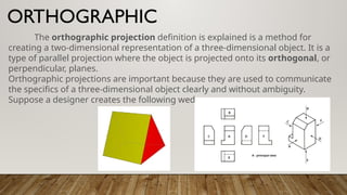
In drafting, projections are a way to represent a 3D
object on a 2D surface. Projections are used in technical
drawings and mechanical design to communicate the
design of an object to manufacturers and builders.
PROJECTION
A projection is the representation of a three-
dimensional object on a two-dimensional surface. In
technical drawing, as in artistic drawing, difficulties arise
when trying to correctly draw an object in three dimensions
on a drafting sheet that has only two dimensions.
How projections work:
•Points of sight: Lines of sight from an
observer pierce the projection plane.
•Projection lines: The points where the lines of
sight pierce the projection plane are connected
to create a projection.
•Image: The figure formed by joining the points
on the projection plane is the image of the
object.
Types of projections:
•Orthographic - A parallel projection where the
projection plane is perpendicular to the lines of
sight. Orthographic projections show the top, front,
and side of an object.
•Isometric - A 3D image drawn on an isometric
grid. Isometric projections appear as if you are viewing
the object from a corner.
•Oblique - A non-orthographic projection where the
lines of sight are not perpendicular to the projection
plane. Oblique projections can be used to illustrate
The orthographic projection definition is explained is a method for
creating a two-dimensional representation of a three-dimensional object. It is a
type of parallel projection where the object is projected onto its orthogonal, or
perpendicular, planes.
Orthographic projections are important because they are used to communicate
the specifics of a three-dimensional object clearly and without ambiguity.
Suppose a designer creates the following wedge:
ORTHOGRAPHIC
An isometric drawing is a three-
dimensional drawing created on a flat two-
dimensional surface. The drawing shows
three views of the image. The views are the
top and two sides. The drawing will have
width, height, and depth.
ISOMETRIC
The definition of an isometric drawing is a drawing of a three-
dimensional shape on a two-dimensional surface along a vertical line with at
least two identified points. All the horizontal lines of the image are created from
the predetermined vertical line at 30-degree angles. The angles play a huge part
in creating the three-dimensional, isometric view.
The drawing of a cube is a very common isometric drawing. Three
dimensions can easily been seen when viewing a cube.
OBLIQUE PROJECTION
This is such type of projection in which
two-dimensional drawings are prepared of
three-dimensional objects.
This is such type of projection in the
drawing of which such projectors are drawn,
which are at some angle other than 90° with
the plane.
The projection lines are drawn at 45°angle. This view
resembles the orthographic projection.
Types OF Oblique Projection:
Following are the two types of oblique projection
according to construction.
1. Cavalier Oblique Drawing.
2. Cabinet Oblique Drawing.
1. Cavalier Oblique Drawing:
Mostly this type of drawing is constructed in
Oblique Projection. In this drawing, one axis is
horizontal, and the other is vertical while the third
axis is at 45° to the horizontal line.
2. Cabinet Oblique Drawing:
In this drawing, one axis is horizontal, and the other is vertical
while the third axis is from 30° to 60° to the horizontal line.
Such drawing resembles much with the actual image.
The dimensions on the horizontal and vertical axes are given from
the actual scale, whereas the scale on the inclined plane is 1/2 or 2/3
of the actual scale.

PROJECTIONS USED IN TECHNICAL DRAFTING.pptx

  • 1.
    In drafting, projectionsare a way to represent a 3D object on a 2D surface. Projections are used in technical drawings and mechanical design to communicate the design of an object to manufacturers and builders. PROJECTION A projection is the representation of a three- dimensional object on a two-dimensional surface. In technical drawing, as in artistic drawing, difficulties arise when trying to correctly draw an object in three dimensions on a drafting sheet that has only two dimensions.
  • 2.
    How projections work: •Pointsof sight: Lines of sight from an observer pierce the projection plane. •Projection lines: The points where the lines of sight pierce the projection plane are connected to create a projection. •Image: The figure formed by joining the points on the projection plane is the image of the object.
  • 3.
    Types of projections: •Orthographic- A parallel projection where the projection plane is perpendicular to the lines of sight. Orthographic projections show the top, front, and side of an object. •Isometric - A 3D image drawn on an isometric grid. Isometric projections appear as if you are viewing the object from a corner. •Oblique - A non-orthographic projection where the lines of sight are not perpendicular to the projection plane. Oblique projections can be used to illustrate
  • 4.
    The orthographic projectiondefinition is explained is a method for creating a two-dimensional representation of a three-dimensional object. It is a type of parallel projection where the object is projected onto its orthogonal, or perpendicular, planes. Orthographic projections are important because they are used to communicate the specifics of a three-dimensional object clearly and without ambiguity. Suppose a designer creates the following wedge: ORTHOGRAPHIC
  • 5.
    An isometric drawingis a three- dimensional drawing created on a flat two- dimensional surface. The drawing shows three views of the image. The views are the top and two sides. The drawing will have width, height, and depth. ISOMETRIC
  • 6.
    The definition ofan isometric drawing is a drawing of a three- dimensional shape on a two-dimensional surface along a vertical line with at least two identified points. All the horizontal lines of the image are created from the predetermined vertical line at 30-degree angles. The angles play a huge part in creating the three-dimensional, isometric view. The drawing of a cube is a very common isometric drawing. Three dimensions can easily been seen when viewing a cube.
  • 7.
    OBLIQUE PROJECTION This issuch type of projection in which two-dimensional drawings are prepared of three-dimensional objects. This is such type of projection in the drawing of which such projectors are drawn, which are at some angle other than 90° with the plane. The projection lines are drawn at 45°angle. This view resembles the orthographic projection.
  • 9.
    Types OF ObliqueProjection: Following are the two types of oblique projection according to construction. 1. Cavalier Oblique Drawing. 2. Cabinet Oblique Drawing.
  • 10.
    1. Cavalier ObliqueDrawing: Mostly this type of drawing is constructed in Oblique Projection. In this drawing, one axis is horizontal, and the other is vertical while the third axis is at 45° to the horizontal line.
  • 11.
    2. Cabinet ObliqueDrawing: In this drawing, one axis is horizontal, and the other is vertical while the third axis is from 30° to 60° to the horizontal line. Such drawing resembles much with the actual image. The dimensions on the horizontal and vertical axes are given from the actual scale, whereas the scale on the inclined plane is 1/2 or 2/3 of the actual scale.