Download to read offline
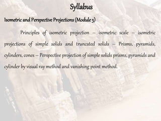
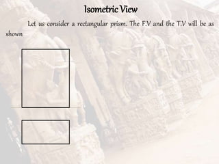
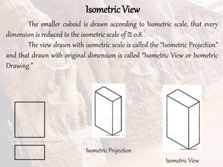
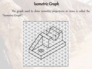
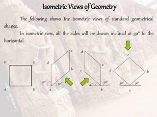
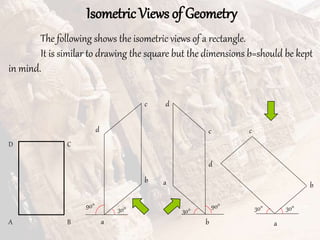
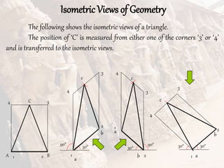
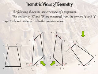
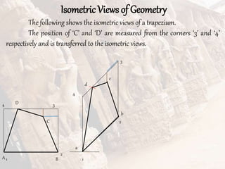
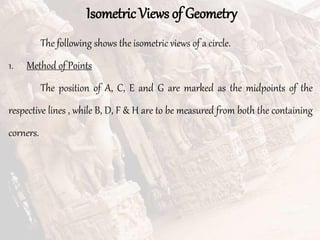
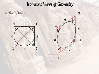
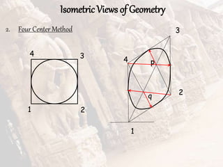
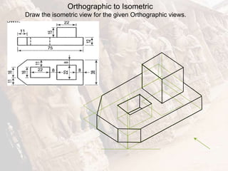
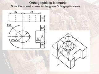
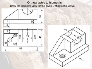
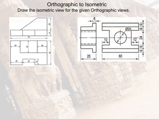
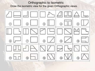
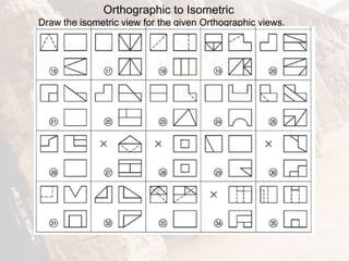
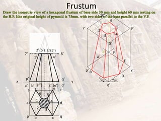
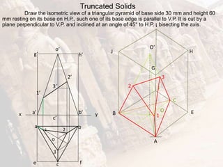
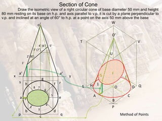
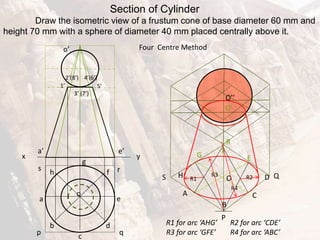
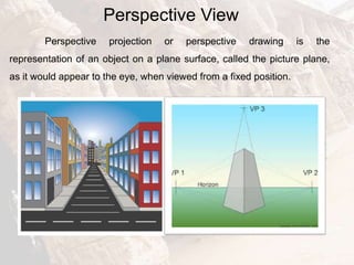
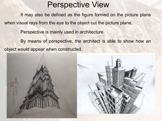
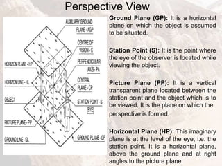
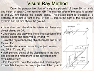
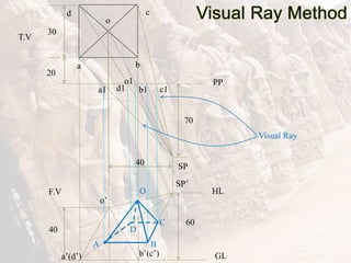
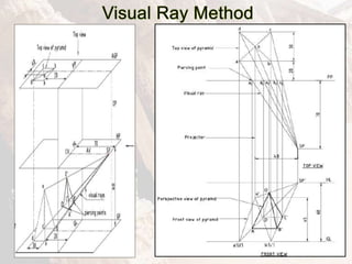
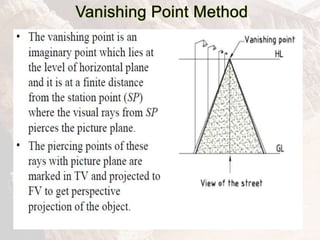
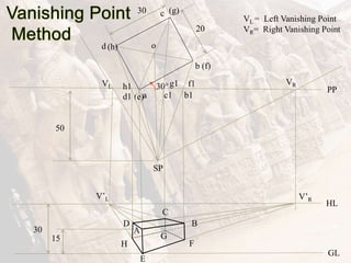
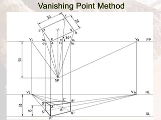


The document provides information on isometric and perspective projections in engineering graphics. It defines isometric projection as a type of pictorial projection that shows the actual sizes of all three dimensions of a solid in a single view. It also defines perspective projection as representing how an object would appear to the eye from a fixed position. The document then discusses principles, scales, views and methods of isometric projection. It provides examples of isometric views of basic geometrical shapes. It also discusses the principles and methods of perspective projection like visual ray and vanishing point methods.