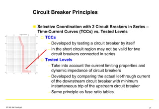
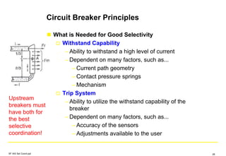
The document discusses selective coordination in electrical systems and circuit breakers. It begins with definitions of selective coordination from the National Electrical Code. It then outlines requirements for selective coordination in the NEC, including for health care facilities, elevators, emergency systems, and legally required standby systems. The document presents the challenges of achieving selective coordination with circuit breakers due to tolerances in instantaneous trip settings. It describes circuit breaker principles for time-current curves and selective override functions. The goal is to provide guidelines for selectively coordinating circuit breakers to meet NEC requirements.

![Challenges Meeting the NEC
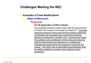
Examples of Code Modifications
State of California
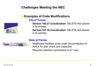
– Healthcare facilities come under the jurisdiction of
OSHPD for plan check and inspection
– Proposals
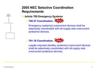
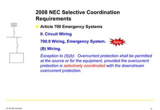
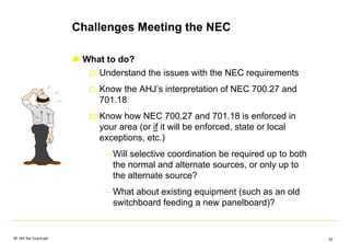
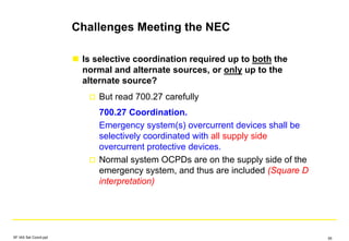
– 700.27 Coordination. Emergency system(s)
overcurrent devices shall be selectively
coordinated with all supply side overcurrent
protective devices. [Not permitted for OSHPD 1, 2,
3, & 4]
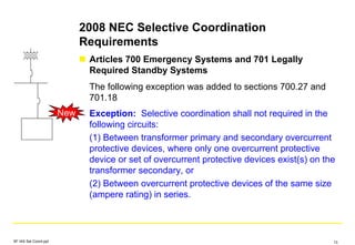
– 701.18 Coordination. Legally required standby
system(s) overcurrent devices shall be selectively
coordinated with all supply side overcurrent
protective devices. [Not permitted for OSHPD 1, 2,
3, & 4]
SF IAS Sel Coord.ppt 59](https://image.slidesharecdn.com/200803selcoord-151227210659/85/Selective-Coordination-59-320.jpg)
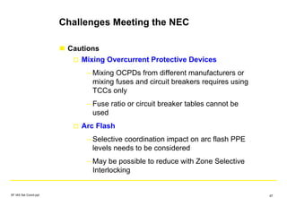
![Challenges Meeting the NEC
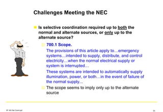
Cautions
Make sure automatic transfer switches have
adequate withstand ratings
– May need to relocate the switch, or
– May need to increase the frame size of the
switch
Make sure busway has adequate withstand ratings
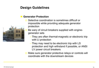
Make sure the generator protection devices
coordinate with the downstream circuit breakers
Total ground fault selective coordination may not be
possible, or may be difficult, due to other Code
requirements [517.17(B)(1) and (2)]
SF IAS Sel Coord.ppt 66](https://image.slidesharecdn.com/200803selcoord-151227210659/85/Selective-Coordination-66-320.jpg)