


![Quotation of Components are used in panel manufacturing
“Soham”, 6/11, Govt.Co.Op. Housing Society, 150 Feet Raiya Road, B/h. Kidvainagar, Rajkot – 360 005.
Email : niyati_engineers@rediffmail.com, niyati.engineers@sify.com
Ref. No. Date : 26/9/2015
To,
H.O.D Electrical
Dr. Subhas Technical Campus.-JUNAGADH.
Subject.
Quatation For Radial Feeder Project.
Dear Sir,
With reference to the above please find our Budgetary Brief proposals as under :
BILL OF MATERIAL FOR POWER PANEL
Sr. No item Rating Qty Price of item Total price
1
Over Current Relay (2 OC + 1 EF) Electro
Mechanical Relay 11kv 2 14500 29000
2Digital Voltage. Meter 1 850 850
3Digital Amp. Meter 1 850 850
4MCB 10ka C Curve 6A 1 750 750
5Toggle Switch 2A 3 45 135
6Relay 2 no+nc 6A 3 275 825
7CT Short Link Terminal 12 125 1500
8LED indicator 230V AC 6 45 270
9Push button With Elements 6 80 480
10Flexible Wire (in meters) 1 sqmm 20 14 280
11Nut, bots, lugs Etc. 1 500 500
12Panel Box. 1 2000 2000
TOTAL 37440
We hope that the offer will be in line with your requirement and favour us with order please feel free to contact us in case you have any quarries.
Thanking you,
_________________________________
For, Niyati Engineers
Note: [1] Payment 30% WITH IN 7 DAYS FROM THE DATE OF BILL ,Balance 50% - 30 days credit
04/22/2016
11
A Review of Radial
Feeder Protection
Concept](https://image.slidesharecdn.com/3c9ce4c5-de8a-4337-b58e-c361f6df1c55-170210132918/85/RADIAL-FEEDER-PROTECTION-PANEL-DEVELOPMENT-11-320.jpg)
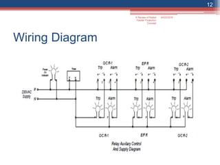

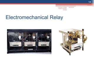
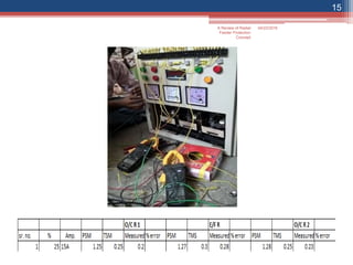
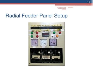

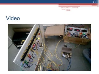


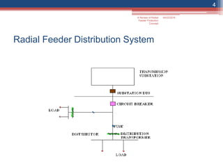
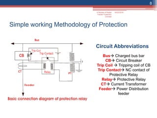
This document summarizes a presentation on radial feeder protection concepts. It discusses the components of a radial feeder distribution system and protective schemes to avoid malfunctions. It then describes the setup of a radial feeder protection panel that students can use to learn fundamentals of protection. Electromechanical relays, wiring diagrams, and photos of the physical panel are shown. The conclusion discusses how faults can be protected against and how the hands-on project helps students understand basic protection terminology.


![protection of transmission lines[distance relay protection scheme]](https://cdn.slidesharecdn.com/ss_thumbnails/os-exe3-23-may2011-sr-i-776s21tr-lineprotection-120425095503-phpapp02-thumbnail.jpg?width=640&height=640&fit=bounds)


