Download as PDF, PPTX


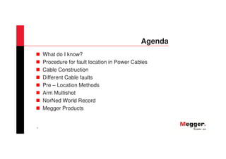

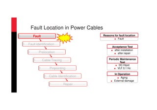
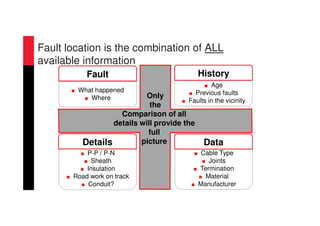
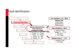
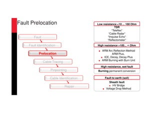
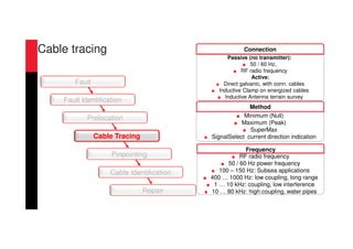
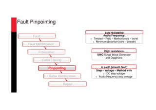
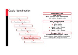
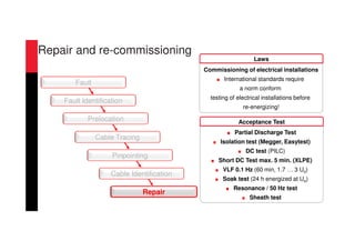
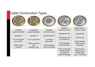
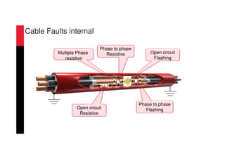
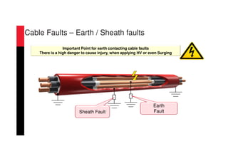
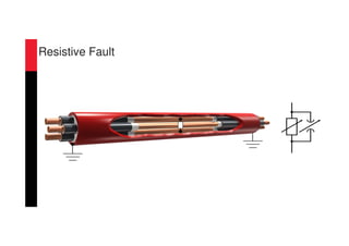
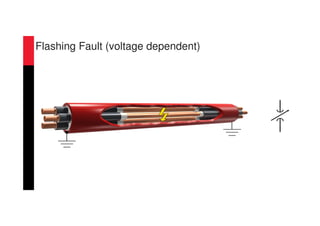

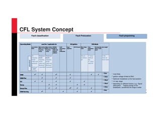
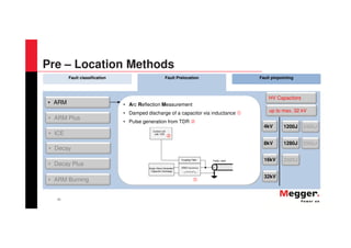


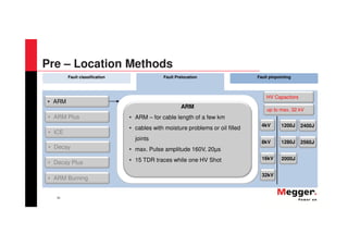
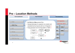

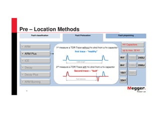
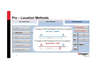
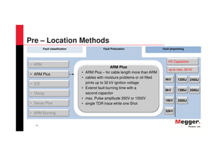
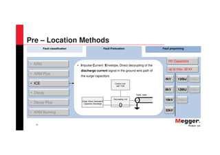
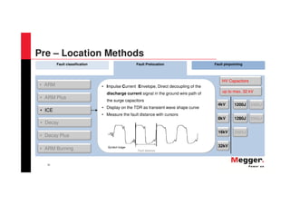
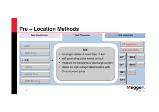
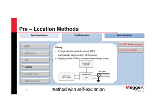
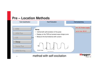
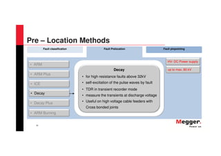
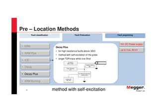
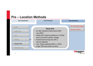
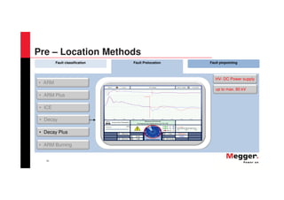
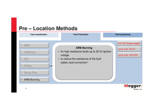
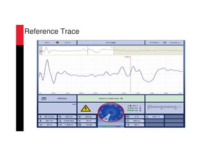
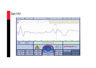

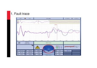


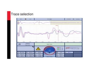


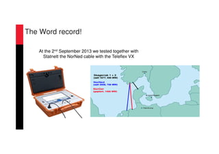
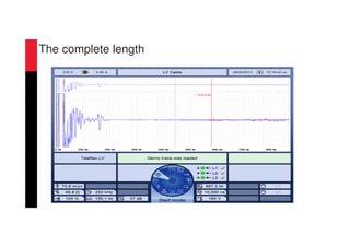
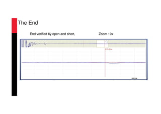
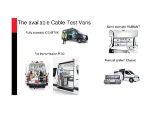


The document discusses various methods and technologies for locating faults in power cables, detailing procedures and technologies for pre-location and pinpointing fault locations. It covers fault construction types, electromagnetic methods, reflection measurement techniques, and the importance of gathering comprehensive data for effective fault identification and repair. Additionally, it highlights the Norned project as a notable example of high-voltage direct current (HVDC) technology and emphasizes the company's commitment to developing reliable test equipment for the electrical supply industry.