Download as PDF, PPTX


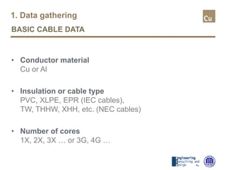
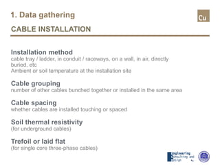
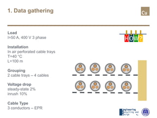
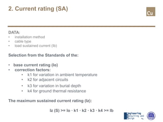


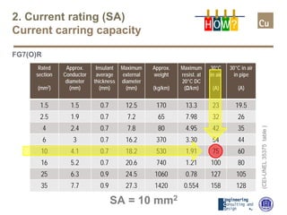
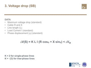

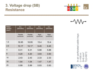
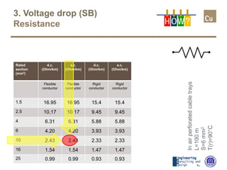

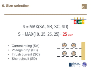


The document provides a comprehensive overview of cable sizing, detailing the process of selecting appropriate electrical cable sizes based on various parameters such as current rating, voltage drop, and installation conditions. It outlines the necessary data collection methods, including cable material, insulation type, installation method, and environmental factors. The document also elaborates on factors affecting current-carrying capacity and voltage drop, along with specific calculations and standards to guide the sizing process.


