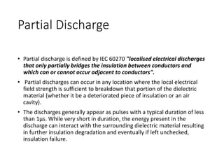
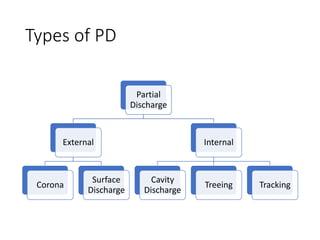
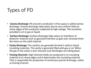
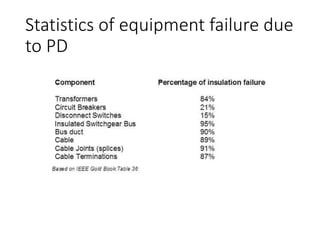
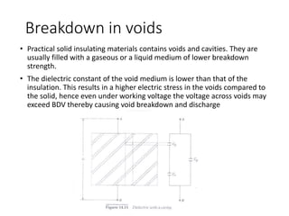
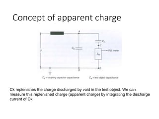
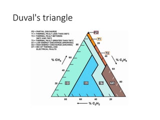
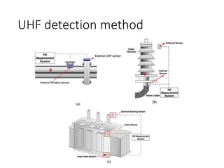
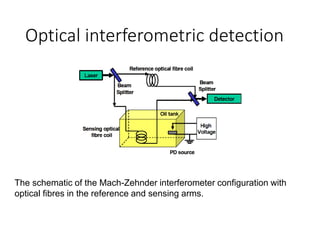
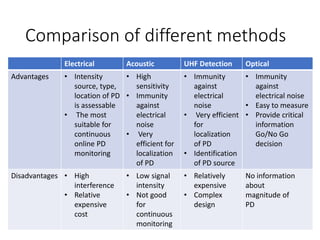
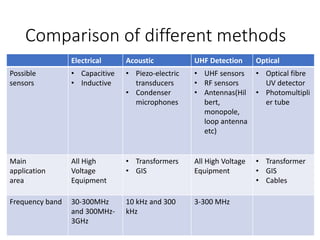
Partial Discharge Testing
By
Debojyoti Mukherjee
(001810802021)
Electrical Engineering Department
Jadavpur University
Partial Discharge
• Partial discharge is defined by IEC 60270 "localised electrical discharges
that only partially bridges the insulation between conductors and
which can or cannot occur adjacent to conductors".
• Partial discharges can occur in any location where the local electrical
field strength is sufficient to breakdown that portion of the dielectric
material (whether it be a deteriorated piece of insulation or an air
cavity).
• The discharges generally appear as pulses with a typical duration of less
than 1µs. While very short in duration, the energy present in the
discharge can interact with the surrounding dielectric material resulting
in further insulation degradation and eventually if left unchecked,
insulation failure.
Types of PD
Partial
Discharge
External
Corona
Surface
Discharge
Internal
Cavity
Discharge
Treeing Tracking
Types of PD
• Corona Discharge: PD around a conductor in free space is called corona
discharge. Corona discharge takes place due to non-uniform field on
sharp edges of the conductor subjected to high voltage. The insulation
provided is air or gas or liquid.
• Surface Discharge: Surface discharge takes place on interfaces of
dielectric material such as gas/solid interface as gets over stressed times
the stress on the solid material.
• Cavity Discharge: The cavities are generally formed in solid or liquid
insulating materials. The cavity is generally filled with gas or air. When
the gas in the cavity is over stressed such discharges are taking place.
• Treeing Channels: High intensity fields are produced in an insulating
material at its sharp edges and it deteriorates the insulating material.
That is responsible for production of continuous partial discharge, called
as treeing channel.
Statistics of equipment failure due
to PD
Breakdown in voids
• Practical solid insulating materials contains voids and cavities. They are
usually filled with a gaseous or a liquid medium of lower breakdown
strength.
• The dielectric constant of the void medium is lower than that of the
insulation. This results in a higher electric stress in the voids compared to
the solid, hence even under working voltage the voltage across voids may
exceed BDV thereby causing void breakdown and discharge
PD detection methods
PD Detection
Non-
conventional
Acoustic
UHF
detection
Optical
Conventional
Electrical Chemical
ELECTRICAL METHOD
Concept of apparent charge
Ck replenishes the charge discharged by void in the test object. We can
measure this replenished charge (apparent charge) by integrating the discharge
current of Ck
Discharge magnitude obtained
from PD pulse
Concept of apparent charge
Detecting PD models from pulse
shape
Pulse Parameters (ns)
PD type Tr Td T50% T10% Ttotal
Internal
Discharge
5-6 10-11 13-14 19-21 80-90
Surface
Discharge
6-8 9-10 11-13 14-16 140-150
Bubble
Discharge
3-4 9-11 11-13 14-15 120-140
Floating
part
discharge
8-9 11-12 18-19 28-30 290-300
CHEMICAL METHODS
DGA testing
• When PD or other kinds of incipent fault occurs in
insulations, gases are generated and they remain
dissolved in the oil.
• Dissolved Gas Analysis is a routine test for
transformers where oil sample is collected and
the amount of gas is detected using gas
chromatography.
• The concentration of gases indicate wheater fault
exists and the type of fault.
Duval's triangle
ACOUSTIC METHOD
Acoustic method
• Acoustic emission detection has been successfully used in order to localize
the PD source inside of the test object as the acoustic signal is strongly
dependent upon the geometry of the test object. This method is very
efficient for localizing PD source because of its immunity against
electromagnetic noise
• The acoustic method is very attractive alternative for online partial
discharge detection in power transformers. The transformer tank is
grounded; therefore the sensors can be placed in a safe way, over any point
of any wall of transformer tank in order to detect the acoustic emission of
partial discharges
• Because power transformers are not homogeneous devices, the waves do
not travel in perfect spherical wave fronts because the source of PD is so
small.
• Classically, due to the many attenuation mechanisms, received acoustic
signals have very low intensity and so sensors must be very responsive to
small changes in signal amplitude in order to detect a PD
Location of PD
UHF DETECTION
UHF detection method
• UHF PD detection has an advantage of strong anti-interference ability
over traditional detection approaches
• Application of UHF PD detection is mostly limited to GIS but in recent
years transformer, cable applications are also considered
• This method is ideal for joints and accessories, with sensors being
located on the joints or accessories
• Electro Magnetic Field detection picks up the radio waves generated by
the partial discharge. And these radio waves can generate TEVs on the
surrounding metalwork. More sensitive measurement, particularly at
higher voltages, can be achieved using in built UHF antennas or external
antenna mounted on insulating spacers in the surrounding metalwork.
UHF detection method
OPTICAL METHODS
Optical PD detection
• The optical partial discharge detection is based on the detection of the
light produced as a result of various ionization, excitation and
recombination processes during the discharge. However, the optical
spectrum of different types of discharge is not the same.
• The main advantages of this method are the immunity from
electromagnetic interferences and high sensitivity compared to
conventional electrical techniques
• The amount of the emitted light and its wavelength depends on the
insulation medium (gaseous, liquid or solid) and different factors
(temperature, pressure …). So the spectrum of the light emitted by
partial discharges depends on the surrounding medium and the
intensity of the discharge.
• 90% of the total energy of the emitted optical spectrum of PD is in the
ultraviolet region.
Optical interferometric detection
The schematic of the Mach-Zehnder interferometer configuration with
optical fibres in the reference and sensing arms.
Comparison of different methods
Electrical Acoustic UHF Detection Optical
Advantages • Intensity
source, type,
location of PD
is assessable
• The most
suitable for
continuous
online PD
monitoring
• High
sensitivity
• Immunity
against
electrical
noise
• Very
efficient for
localization
of PD
• Immunity
against
electrical
noise
• Very efficient
for
localization
of PD
• Identification
of PD source
• Immunity
against
electrical noise
• Easy to measure
• Provide critical
information
Go/No Go
decision
Disadvantages • High
interference
• Relative
expensive
cost
• Low signal
intensity
• Not good
for
continuous
monitoring
• Relatively
expensive
• Complex
design
No information
about
magnitude of
PD
Comparison of different methods
Electrical Acoustic UHF Detection Optical
Possible
sensors
• Capacitive
• Inductive
• Piezo-electric
transducers
• Condenser
microphones
• UHF sensors
• RF sensors
• Antennas(Hil
bert,
monopole,
loop antenna
etc)
• Optical fibre
UV detector
• Photomultipli
er tube
Main
application
area
All High
Voltage
Equipment
• Transformers
• GIS
All High Voltage
Equipment
• Transformer
• GIS
• Cables
Frequency band 30-300MHz
and 300MHz-
3GHz
10 kHz and 300
kHz
3-300 MHz
REFERENCES
• Study on different techniques of partial discharge(PD) detection in power
transformers winding: Simulation between paper and EPOXY resin using UHF
method--International Journal of Conceptions on Electrical and Electronics
Engineering--Irfan Ali Soomro and Md Nor Ramdon
• STUDY ON PULSE CURRENT OF TYPICAL PD MODELS IN POWER TRANSFORMER--
Guoli Wang, Yanpeng Hao, Yanming Li
• EXPERIENCE WITH OPTICAL PARTIAL DISCHARGE DETECTION--Michael Muhr,
Robert Schwarz
• Fiber Optic Sensor for Acoustic Detection of Partial Discharges in Oil-Paper
Insulated Electrical Systems--Julio Posada-Roman, Jose A. Garcia-Souto and
Jesus Rubio-Serrano

Partial discharge testing

  • 1.
    Partial Discharge Testing By DebojyotiMukherjee (001810802021) Electrical Engineering Department Jadavpur University
  • 2.
    Partial Discharge • Partialdischarge is defined by IEC 60270 "localised electrical discharges that only partially bridges the insulation between conductors and which can or cannot occur adjacent to conductors". • Partial discharges can occur in any location where the local electrical field strength is sufficient to breakdown that portion of the dielectric material (whether it be a deteriorated piece of insulation or an air cavity). • The discharges generally appear as pulses with a typical duration of less than 1µs. While very short in duration, the energy present in the discharge can interact with the surrounding dielectric material resulting in further insulation degradation and eventually if left unchecked, insulation failure.
  • 3.
  • 4.
    Types of PD •Corona Discharge: PD around a conductor in free space is called corona discharge. Corona discharge takes place due to non-uniform field on sharp edges of the conductor subjected to high voltage. The insulation provided is air or gas or liquid. • Surface Discharge: Surface discharge takes place on interfaces of dielectric material such as gas/solid interface as gets over stressed times the stress on the solid material. • Cavity Discharge: The cavities are generally formed in solid or liquid insulating materials. The cavity is generally filled with gas or air. When the gas in the cavity is over stressed such discharges are taking place. • Treeing Channels: High intensity fields are produced in an insulating material at its sharp edges and it deteriorates the insulating material. That is responsible for production of continuous partial discharge, called as treeing channel.
  • 5.
    Statistics of equipmentfailure due to PD
  • 6.
    Breakdown in voids •Practical solid insulating materials contains voids and cavities. They are usually filled with a gaseous or a liquid medium of lower breakdown strength. • The dielectric constant of the void medium is lower than that of the insulation. This results in a higher electric stress in the voids compared to the solid, hence even under working voltage the voltage across voids may exceed BDV thereby causing void breakdown and discharge
  • 7.
    PD detection methods PDDetection Non- conventional Acoustic UHF detection Optical Conventional Electrical Chemical
  • 8.
  • 9.
    Concept of apparentcharge Ck replenishes the charge discharged by void in the test object. We can measure this replenished charge (apparent charge) by integrating the discharge current of Ck
  • 10.
  • 11.
  • 12.
    Detecting PD modelsfrom pulse shape Pulse Parameters (ns) PD type Tr Td T50% T10% Ttotal Internal Discharge 5-6 10-11 13-14 19-21 80-90 Surface Discharge 6-8 9-10 11-13 14-16 140-150 Bubble Discharge 3-4 9-11 11-13 14-15 120-140 Floating part discharge 8-9 11-12 18-19 28-30 290-300
  • 13.
  • 14.
    DGA testing • WhenPD or other kinds of incipent fault occurs in insulations, gases are generated and they remain dissolved in the oil. • Dissolved Gas Analysis is a routine test for transformers where oil sample is collected and the amount of gas is detected using gas chromatography. • The concentration of gases indicate wheater fault exists and the type of fault.
  • 15.
  • 16.
  • 17.
    Acoustic method • Acousticemission detection has been successfully used in order to localize the PD source inside of the test object as the acoustic signal is strongly dependent upon the geometry of the test object. This method is very efficient for localizing PD source because of its immunity against electromagnetic noise • The acoustic method is very attractive alternative for online partial discharge detection in power transformers. The transformer tank is grounded; therefore the sensors can be placed in a safe way, over any point of any wall of transformer tank in order to detect the acoustic emission of partial discharges • Because power transformers are not homogeneous devices, the waves do not travel in perfect spherical wave fronts because the source of PD is so small. • Classically, due to the many attenuation mechanisms, received acoustic signals have very low intensity and so sensors must be very responsive to small changes in signal amplitude in order to detect a PD
  • 18.
  • 19.
  • 20.
    UHF detection method •UHF PD detection has an advantage of strong anti-interference ability over traditional detection approaches • Application of UHF PD detection is mostly limited to GIS but in recent years transformer, cable applications are also considered • This method is ideal for joints and accessories, with sensors being located on the joints or accessories • Electro Magnetic Field detection picks up the radio waves generated by the partial discharge. And these radio waves can generate TEVs on the surrounding metalwork. More sensitive measurement, particularly at higher voltages, can be achieved using in built UHF antennas or external antenna mounted on insulating spacers in the surrounding metalwork.
  • 21.
  • 22.
  • 23.
    Optical PD detection •The optical partial discharge detection is based on the detection of the light produced as a result of various ionization, excitation and recombination processes during the discharge. However, the optical spectrum of different types of discharge is not the same. • The main advantages of this method are the immunity from electromagnetic interferences and high sensitivity compared to conventional electrical techniques • The amount of the emitted light and its wavelength depends on the insulation medium (gaseous, liquid or solid) and different factors (temperature, pressure …). So the spectrum of the light emitted by partial discharges depends on the surrounding medium and the intensity of the discharge. • 90% of the total energy of the emitted optical spectrum of PD is in the ultraviolet region.
  • 24.
    Optical interferometric detection Theschematic of the Mach-Zehnder interferometer configuration with optical fibres in the reference and sensing arms.
  • 25.
    Comparison of differentmethods Electrical Acoustic UHF Detection Optical Advantages • Intensity source, type, location of PD is assessable • The most suitable for continuous online PD monitoring • High sensitivity • Immunity against electrical noise • Very efficient for localization of PD • Immunity against electrical noise • Very efficient for localization of PD • Identification of PD source • Immunity against electrical noise • Easy to measure • Provide critical information Go/No Go decision Disadvantages • High interference • Relative expensive cost • Low signal intensity • Not good for continuous monitoring • Relatively expensive • Complex design No information about magnitude of PD
  • 26.
    Comparison of differentmethods Electrical Acoustic UHF Detection Optical Possible sensors • Capacitive • Inductive • Piezo-electric transducers • Condenser microphones • UHF sensors • RF sensors • Antennas(Hil bert, monopole, loop antenna etc) • Optical fibre UV detector • Photomultipli er tube Main application area All High Voltage Equipment • Transformers • GIS All High Voltage Equipment • Transformer • GIS • Cables Frequency band 30-300MHz and 300MHz- 3GHz 10 kHz and 300 kHz 3-300 MHz
  • 27.
    REFERENCES • Study ondifferent techniques of partial discharge(PD) detection in power transformers winding: Simulation between paper and EPOXY resin using UHF method--International Journal of Conceptions on Electrical and Electronics Engineering--Irfan Ali Soomro and Md Nor Ramdon • STUDY ON PULSE CURRENT OF TYPICAL PD MODELS IN POWER TRANSFORMER-- Guoli Wang, Yanpeng Hao, Yanming Li • EXPERIENCE WITH OPTICAL PARTIAL DISCHARGE DETECTION--Michael Muhr, Robert Schwarz • Fiber Optic Sensor for Acoustic Detection of Partial Discharges in Oil-Paper Insulated Electrical Systems--Julio Posada-Roman, Jose A. Garcia-Souto and Jesus Rubio-Serrano