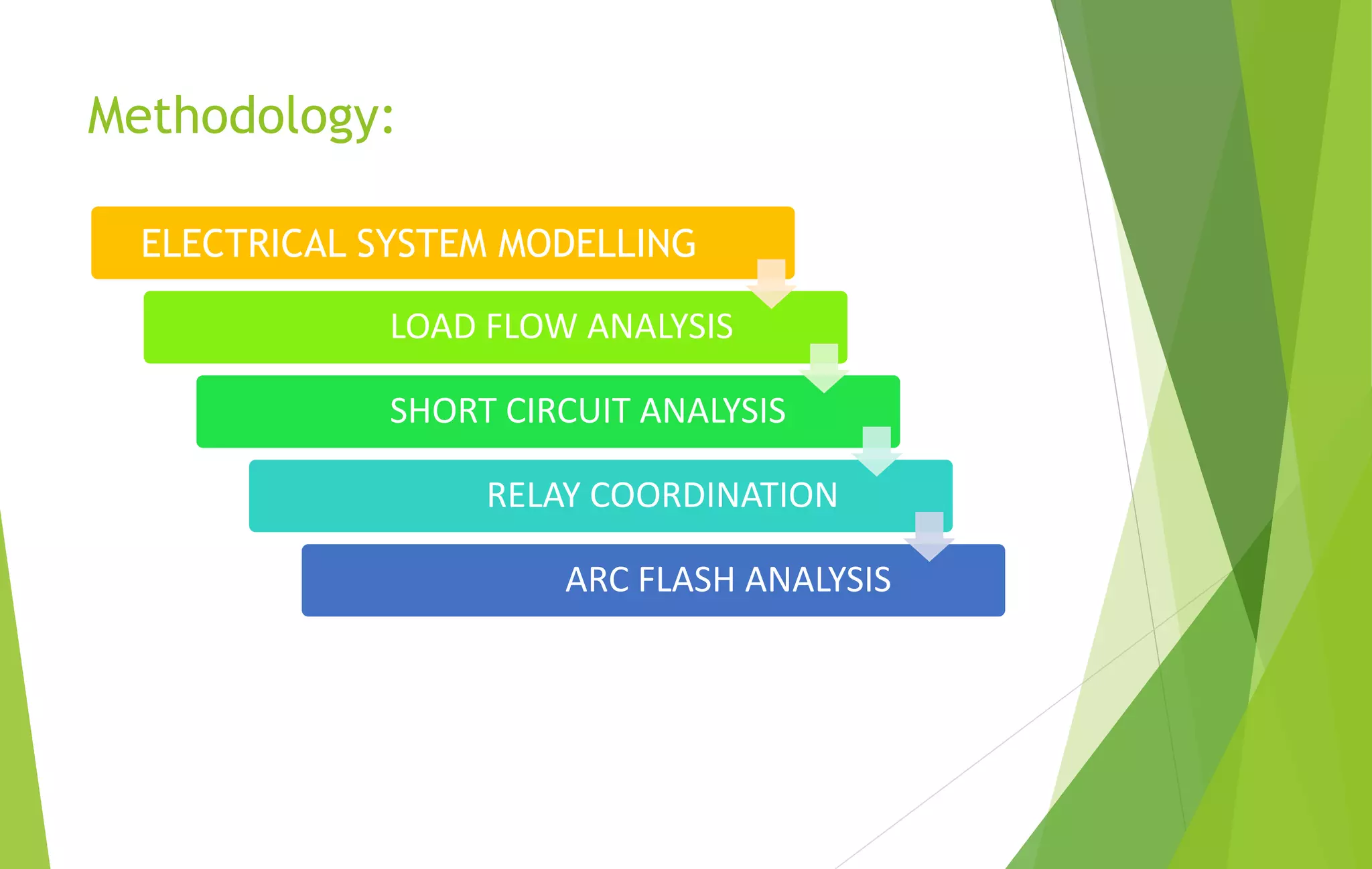
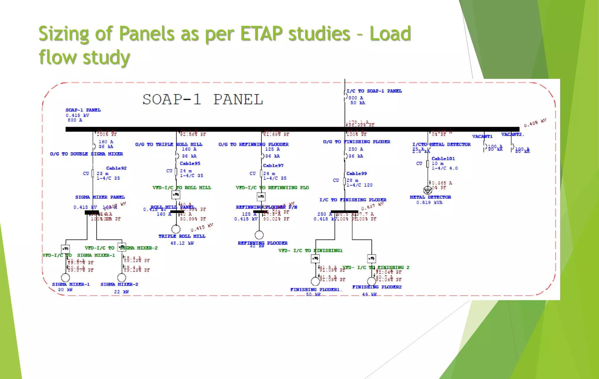
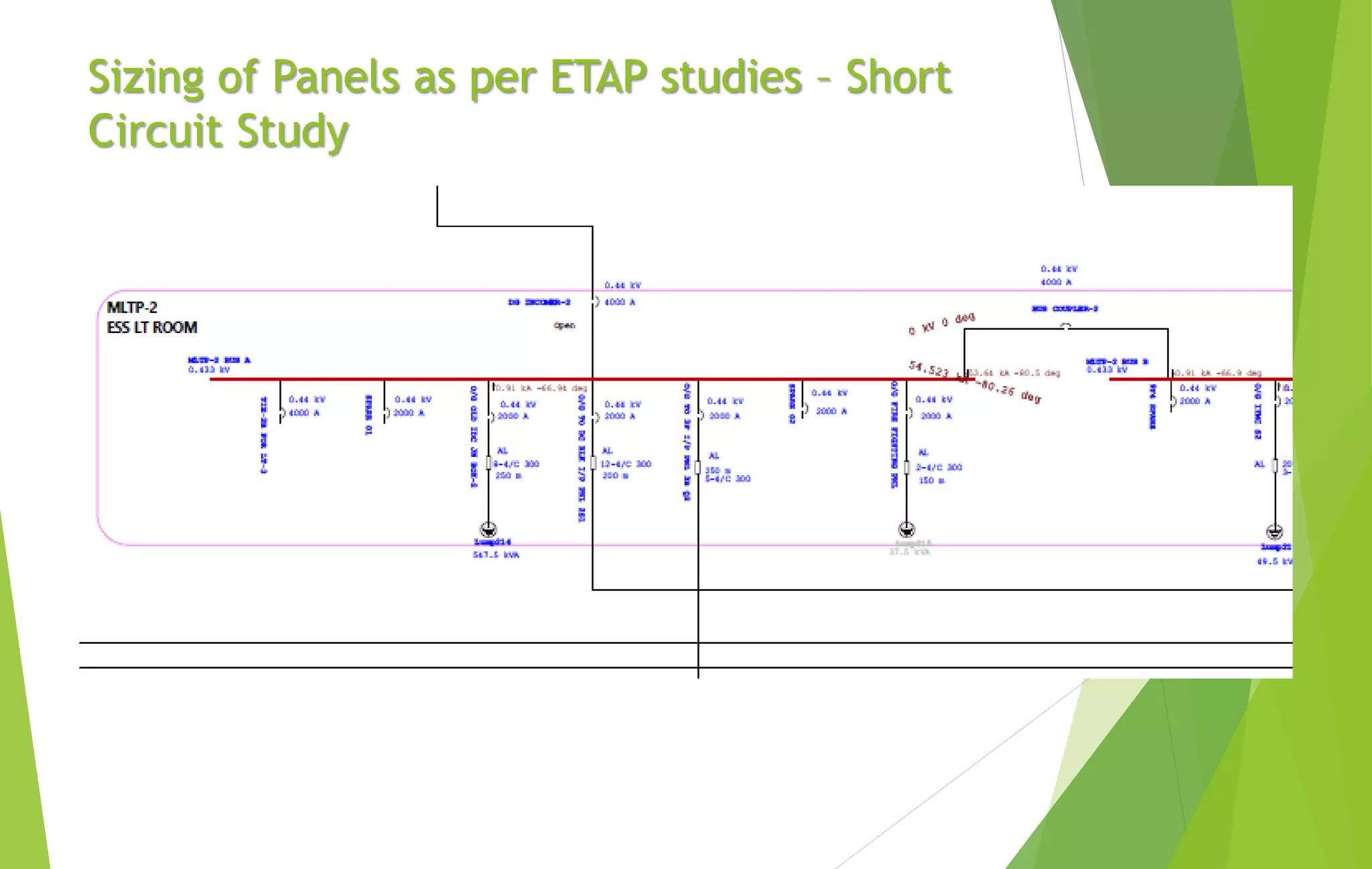
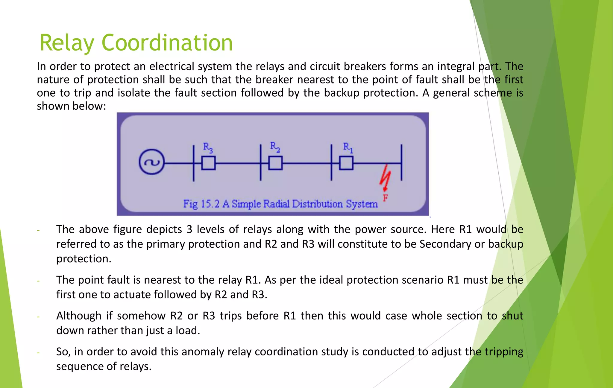
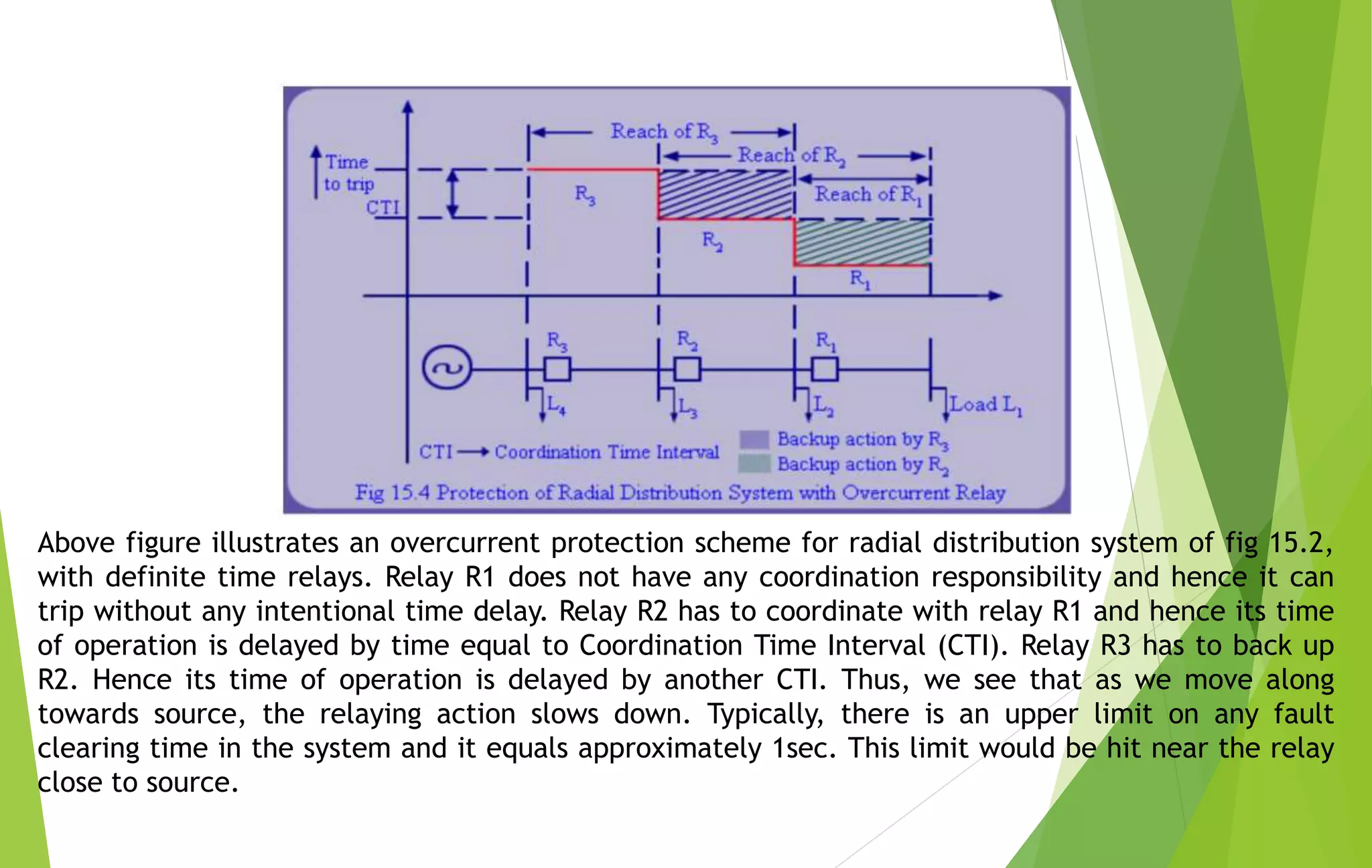
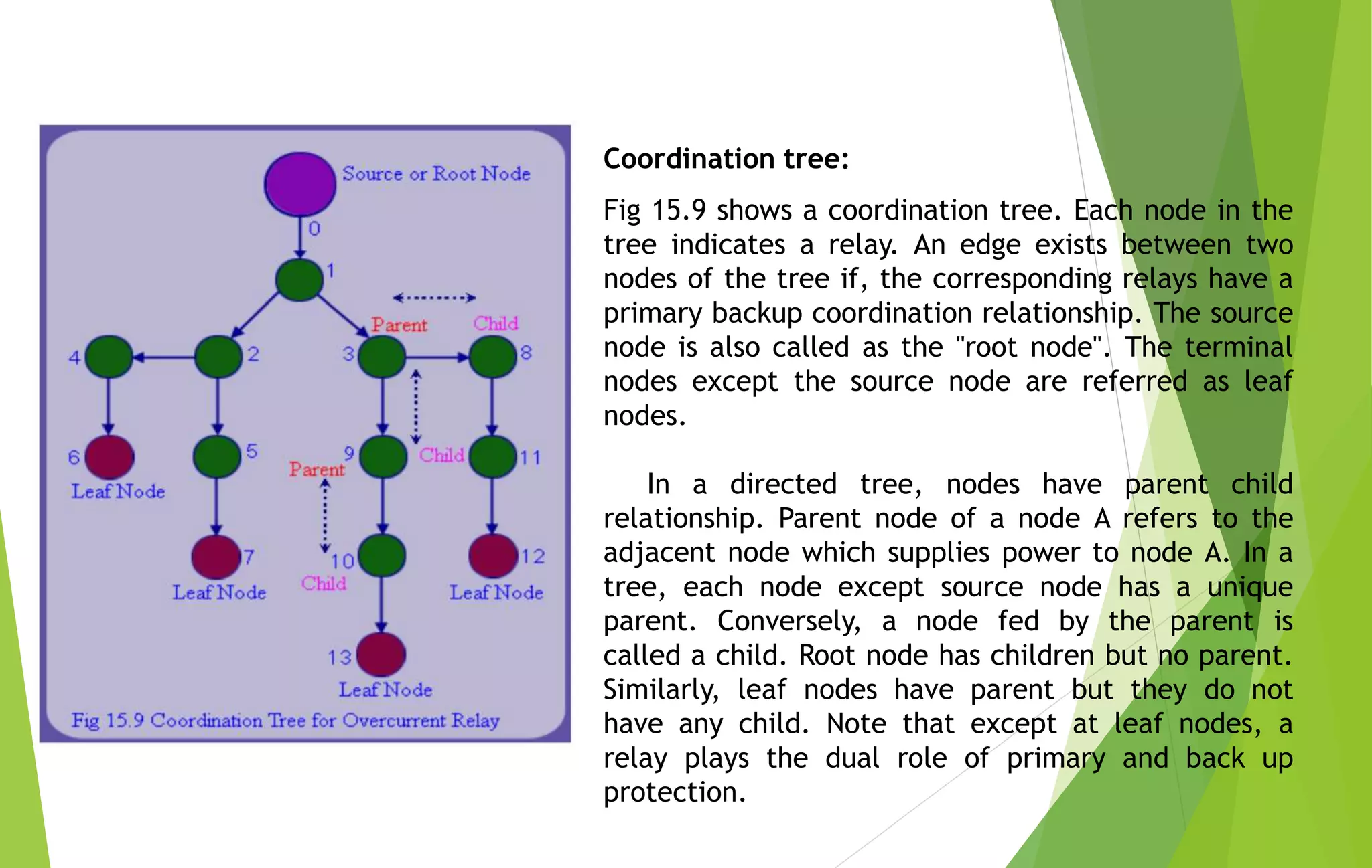
POWER SYSTEM ANALYSIS
USING ETAP
Background:
 Power system analysis is the field of electrical study which deals with the analysis
of electrical power system and it’s behaviour during potential fault scenarios.
 System studies are usually required to be conducted during two major phases of a
project:
- The initial project design phase (Greenfield phase).
- During the modification phase of an existing system (Brown field phase).
 System study is a requisite practice in order to ensure the genuineness of the
multiple system parameters taking into practice during the system design.
 Common parameters taken into consideration during the study are short circuit,
loading, relay settings, motor parameters etc.
 The studies included within system analysis are:
- Load flow study
- Short circuit study
- Relay coordination study
- Arc flash study
- Motor starting study
Why Do We Need Protection:
As we might know an electrical system at times might get exposed to certain conditions
which causes the deviation of voltages and currents from nominal values or states. Under
normal operating conditions, power system equipment or lines carry normal voltages and
currents which results in a safer operation of the system.
But when fault occurs, it causes excessively high currents to flow in a system which causes
damage to the equipment and devices. Thus in order to protect the system from fault its is
necessary to deploy certain protection schemes.
Types of Faults in power system:
1. Symmetrical faults: These are very severe faults and occur infrequently in the power
systems. These are also called as balanced faults and are of two types namely line to
line to line to ground (L-L-L-G) and line to line to line (L-L-L). Only 2-5 percent of
system faults are symmetrical faults.
2. Unsymmetrical faults: These are very common and less severe than symmetrical
faults. There are mainly three types namely line to ground (L-G), line to line (L-L) and
double line to ground (LL-G) faults.
Methodology:
ELECTRICAL SYSTEM MODELLING
LOAD FLOW ANALYSIS
SHORT CIRCUIT ANALYSIS
RELAY COORDINATION
ARC FLASH ANALYSIS
Load Flow Study
 Load flow study is based on analysing the system’s loading scenario i.e. to ensure
whether the loading is proper or not.
 Multiple parameters taken into consideration during the study are the system’s
voltage and current ratings.
 The purpose of this study is:
- To ensure that the voltages at all the buses are maintained with in legitimate
limits.
- To determine the flows in various elements.
- To check that the losses in the system are within the reasonable limits.
- To determine the necessary tap selection for the transformer.
- To determine the active and reactive power flows in the system thereby
performing power factor compensation.
- To ensure that the generator in the system are loaded to within their real and
reactive capability limits.
Short Circuit Analysis
 The purpose of the short circuit study is to analyse the effect of three-phase
(Worst condition of Short Circuit) on the electrical system.
 The fault calculations are in compliance with IEC 60909.
 This study analysis the effect of short circuit fault on the system by taking
into account the fault current contribution of each load on the bus.
 The short circuit study is useful in:
- Determining the total fault current flowing through a bus thereby helping
in selecting the kA rating of the bus.
- Selecting the kA rating of circuit breakers through device duty SC analysis.
- Fault contribution by individual devices.
Sizing of Panels as per ETAP studies
Load Flow Study:
- Power factor of all panels and design capacitor panels as per requirement.
- Voltage drop of at all panels and size cable.
- Overload conditions of all equipment and optimise system design.
Short Circuit Study
- Short circuit current of each panel and selection of all circuit breaker, VCB,
MCCB and fuses as per short circuit current available.
- Cable withstand capacity as per short circuit current available.
Sizing of Panels as per ETAP studies – Load
flow study
Sizing of Panels as per ETAP studies – Short
Circuit Study
Relay Coordination
In order to protect an electrical system the relays and circuit breakers forms an integral part. The
nature of protection shall be such that the breaker nearest to the point of fault shall be the first
one to trip and isolate the fault section followed by the backup protection. A general scheme is
shown below:
- The above figure depicts 3 levels of relays along with the power source. Here R1 would be
referred to as the primary protection and R2 and R3 will constitute to be Secondary or backup
protection.
- The point fault is nearest to the relay R1. As per the ideal protection scenario R1 must be the
first one to actuate followed by R2 and R3.
- Although if somehow R2 or R3 trips before R1 then this would case whole section to shut
down rather than just a load.
- So, in order to avoid this anomaly relay coordination study is conducted to adjust the tripping
sequence of relays.
Above figure illustrates an overcurrent protection scheme for radial distribution system of fig 15.2,
with definite time relays. Relay R1 does not have any coordination responsibility and hence it can
trip without any intentional time delay. Relay R2 has to coordinate with relay R1 and hence its time
of operation is delayed by time equal to Coordination Time Interval (CTI). Relay R3 has to back up
R2. Hence its time of operation is delayed by another CTI. Thus, we see that as we move along
towards source, the relaying action slows down. Typically, there is an upper limit on any fault
clearing time in the system and it equals approximately 1sec. This limit would be hit near the relay
close to source.
Coordination tree:
Fig 15.9 shows a coordination tree. Each node in the
tree indicates a relay. An edge exists between two
nodes of the tree if, the corresponding relays have a
primary backup coordination relationship. The source
node is also called as the "root node". The terminal
nodes except the source node are referred as leaf
nodes.
In a directed tree, nodes have parent child
relationship. Parent node of a node A refers to the
adjacent node which supplies power to node A. In a
tree, each node except source node has a unique
parent. Conversely, a node fed by the parent is
called a child. Root node has children but no parent.
Similarly, leaf nodes have parent but they do not
have any child. Note that except at leaf nodes, a
relay plays the dual role of primary and back up
protection.
Long-Time delay Setting (tr):
• Long time delay (tr) sets length of time that the circuit breaker will
carry a sustained overload before tripping.
• The delay bands are labeled in seconds of over current at six times
the ampere rating.
• Long-time delay is an inverse time characteristic in that the
tripping time decreases as the current increases.
• The long-time delay (tr) sets the length of the time that the circuit
breaker will carry an over current (below the short-time or
instantaneous pickup current level) before tripping.
• The Long time delay can be set to I2t On and I2t OFF settings.
• (A) I2t Response:I2t Out ,For coordination with other circuit
breakers with electronic trip devices and for coordination with
thermal-magnetic circuit breakers.
• (B) I2t Response: I2t In ,For coordination with fuses and upstream
transformer
Relay Settings Criteria
Short Time pickup Current Setting (Im):
• Short time protection is time-independent.
• It determines or sets the level of fault current at which the
short-time trip delay countdown is actuated.
• Short Time Pick up Value (Im) (multiplied by the ampere rating)
sets the short circuit current level at which the circuit breaker
will trip after the set time delay.
• The short-time pickup (Isd) sets current level (below
instantaneous trip level) at which circuit breaker will trip after
the preset time delay.
Standard Practice for Setting:
• No trip for a current below 80% of the short time setting
• Trip for a current equal to 120% of the short time setting
• The trip time is Less than 0.2 s for a short time protection with
no time delay and equal to the value of the time delay tsd for a
protection with time delay
Instantaneous Pickup Setting (Ii):
• Instantaneous protection is time-independent.
• It determines the level of fault current that will actuate a trip
with no time delay.
• Ii value (multiplied by the ampere rating (In)) sets the short-
circuit current level at which the circuit breaker will trip with
no intentional time delay.
• This protection trips to eliminate quickly high value currents
and its trip times cannot be set
• The instantaneous function will override the short-time
function if the instantaneous Pickup is adjusted at the same
or lower setting than the Short Time Pickup.
Thank You

ETAP Training.pptx

  • 1.
  • 2.
    Background:  Power systemanalysis is the field of electrical study which deals with the analysis of electrical power system and it’s behaviour during potential fault scenarios.  System studies are usually required to be conducted during two major phases of a project: - The initial project design phase (Greenfield phase). - During the modification phase of an existing system (Brown field phase).  System study is a requisite practice in order to ensure the genuineness of the multiple system parameters taking into practice during the system design.  Common parameters taken into consideration during the study are short circuit, loading, relay settings, motor parameters etc.  The studies included within system analysis are: - Load flow study - Short circuit study - Relay coordination study - Arc flash study - Motor starting study
  • 3.
    Why Do WeNeed Protection: As we might know an electrical system at times might get exposed to certain conditions which causes the deviation of voltages and currents from nominal values or states. Under normal operating conditions, power system equipment or lines carry normal voltages and currents which results in a safer operation of the system. But when fault occurs, it causes excessively high currents to flow in a system which causes damage to the equipment and devices. Thus in order to protect the system from fault its is necessary to deploy certain protection schemes. Types of Faults in power system: 1. Symmetrical faults: These are very severe faults and occur infrequently in the power systems. These are also called as balanced faults and are of two types namely line to line to line to ground (L-L-L-G) and line to line to line (L-L-L). Only 2-5 percent of system faults are symmetrical faults. 2. Unsymmetrical faults: These are very common and less severe than symmetrical faults. There are mainly three types namely line to ground (L-G), line to line (L-L) and double line to ground (LL-G) faults.
  • 4.
    Methodology: ELECTRICAL SYSTEM MODELLING LOADFLOW ANALYSIS SHORT CIRCUIT ANALYSIS RELAY COORDINATION ARC FLASH ANALYSIS
  • 5.
    Load Flow Study Load flow study is based on analysing the system’s loading scenario i.e. to ensure whether the loading is proper or not.  Multiple parameters taken into consideration during the study are the system’s voltage and current ratings.  The purpose of this study is: - To ensure that the voltages at all the buses are maintained with in legitimate limits. - To determine the flows in various elements. - To check that the losses in the system are within the reasonable limits. - To determine the necessary tap selection for the transformer. - To determine the active and reactive power flows in the system thereby performing power factor compensation. - To ensure that the generator in the system are loaded to within their real and reactive capability limits.
  • 6.
    Short Circuit Analysis The purpose of the short circuit study is to analyse the effect of three-phase (Worst condition of Short Circuit) on the electrical system.  The fault calculations are in compliance with IEC 60909.  This study analysis the effect of short circuit fault on the system by taking into account the fault current contribution of each load on the bus.  The short circuit study is useful in: - Determining the total fault current flowing through a bus thereby helping in selecting the kA rating of the bus. - Selecting the kA rating of circuit breakers through device duty SC analysis. - Fault contribution by individual devices.
  • 7.
    Sizing of Panelsas per ETAP studies Load Flow Study: - Power factor of all panels and design capacitor panels as per requirement. - Voltage drop of at all panels and size cable. - Overload conditions of all equipment and optimise system design. Short Circuit Study - Short circuit current of each panel and selection of all circuit breaker, VCB, MCCB and fuses as per short circuit current available. - Cable withstand capacity as per short circuit current available.
  • 8.
    Sizing of Panelsas per ETAP studies – Load flow study
  • 9.
    Sizing of Panelsas per ETAP studies – Short Circuit Study
  • 10.
    Relay Coordination In orderto protect an electrical system the relays and circuit breakers forms an integral part. The nature of protection shall be such that the breaker nearest to the point of fault shall be the first one to trip and isolate the fault section followed by the backup protection. A general scheme is shown below: - The above figure depicts 3 levels of relays along with the power source. Here R1 would be referred to as the primary protection and R2 and R3 will constitute to be Secondary or backup protection. - The point fault is nearest to the relay R1. As per the ideal protection scenario R1 must be the first one to actuate followed by R2 and R3. - Although if somehow R2 or R3 trips before R1 then this would case whole section to shut down rather than just a load. - So, in order to avoid this anomaly relay coordination study is conducted to adjust the tripping sequence of relays.
  • 11.
    Above figure illustratesan overcurrent protection scheme for radial distribution system of fig 15.2, with definite time relays. Relay R1 does not have any coordination responsibility and hence it can trip without any intentional time delay. Relay R2 has to coordinate with relay R1 and hence its time of operation is delayed by time equal to Coordination Time Interval (CTI). Relay R3 has to back up R2. Hence its time of operation is delayed by another CTI. Thus, we see that as we move along towards source, the relaying action slows down. Typically, there is an upper limit on any fault clearing time in the system and it equals approximately 1sec. This limit would be hit near the relay close to source.
  • 12.
    Coordination tree: Fig 15.9shows a coordination tree. Each node in the tree indicates a relay. An edge exists between two nodes of the tree if, the corresponding relays have a primary backup coordination relationship. The source node is also called as the "root node". The terminal nodes except the source node are referred as leaf nodes. In a directed tree, nodes have parent child relationship. Parent node of a node A refers to the adjacent node which supplies power to node A. In a tree, each node except source node has a unique parent. Conversely, a node fed by the parent is called a child. Root node has children but no parent. Similarly, leaf nodes have parent but they do not have any child. Note that except at leaf nodes, a relay plays the dual role of primary and back up protection.
  • 15.
    Long-Time delay Setting(tr): • Long time delay (tr) sets length of time that the circuit breaker will carry a sustained overload before tripping. • The delay bands are labeled in seconds of over current at six times the ampere rating. • Long-time delay is an inverse time characteristic in that the tripping time decreases as the current increases. • The long-time delay (tr) sets the length of the time that the circuit breaker will carry an over current (below the short-time or instantaneous pickup current level) before tripping. • The Long time delay can be set to I2t On and I2t OFF settings. • (A) I2t Response:I2t Out ,For coordination with other circuit breakers with electronic trip devices and for coordination with thermal-magnetic circuit breakers. • (B) I2t Response: I2t In ,For coordination with fuses and upstream transformer Relay Settings Criteria
  • 16.
    Short Time pickupCurrent Setting (Im): • Short time protection is time-independent. • It determines or sets the level of fault current at which the short-time trip delay countdown is actuated. • Short Time Pick up Value (Im) (multiplied by the ampere rating) sets the short circuit current level at which the circuit breaker will trip after the set time delay. • The short-time pickup (Isd) sets current level (below instantaneous trip level) at which circuit breaker will trip after the preset time delay. Standard Practice for Setting: • No trip for a current below 80% of the short time setting • Trip for a current equal to 120% of the short time setting • The trip time is Less than 0.2 s for a short time protection with no time delay and equal to the value of the time delay tsd for a protection with time delay
  • 17.
    Instantaneous Pickup Setting(Ii): • Instantaneous protection is time-independent. • It determines the level of fault current that will actuate a trip with no time delay. • Ii value (multiplied by the ampere rating (In)) sets the short- circuit current level at which the circuit breaker will trip with no intentional time delay. • This protection trips to eliminate quickly high value currents and its trip times cannot be set • The instantaneous function will override the short-time function if the instantaneous Pickup is adjusted at the same or lower setting than the Short Time Pickup.
  • 18.