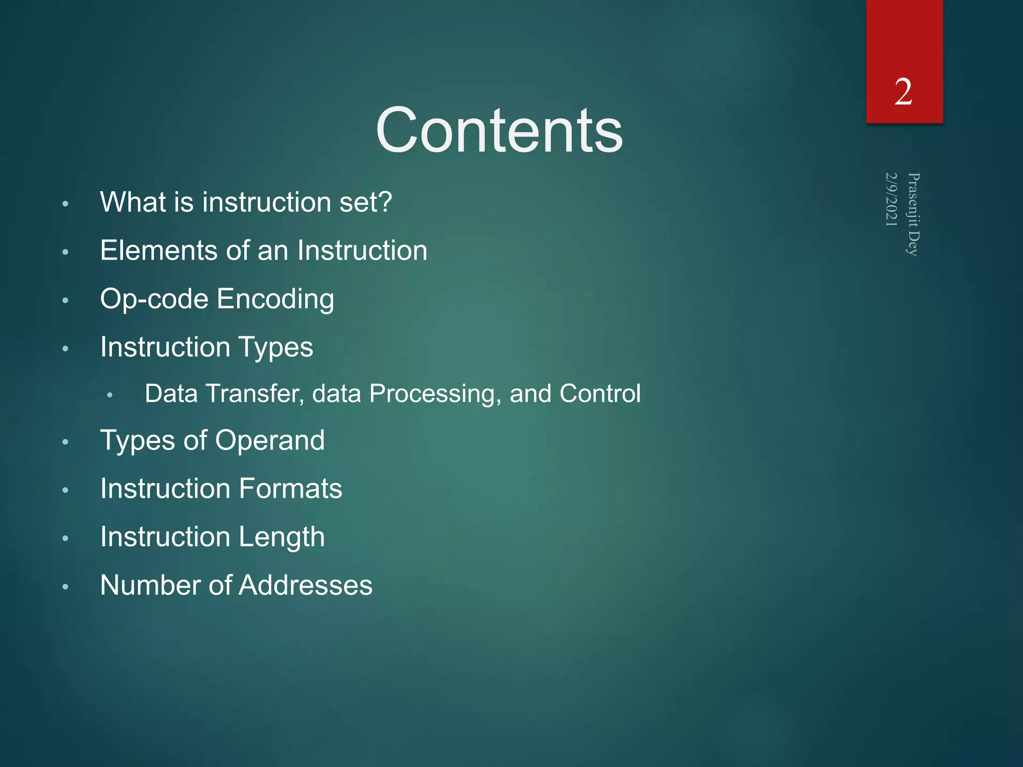

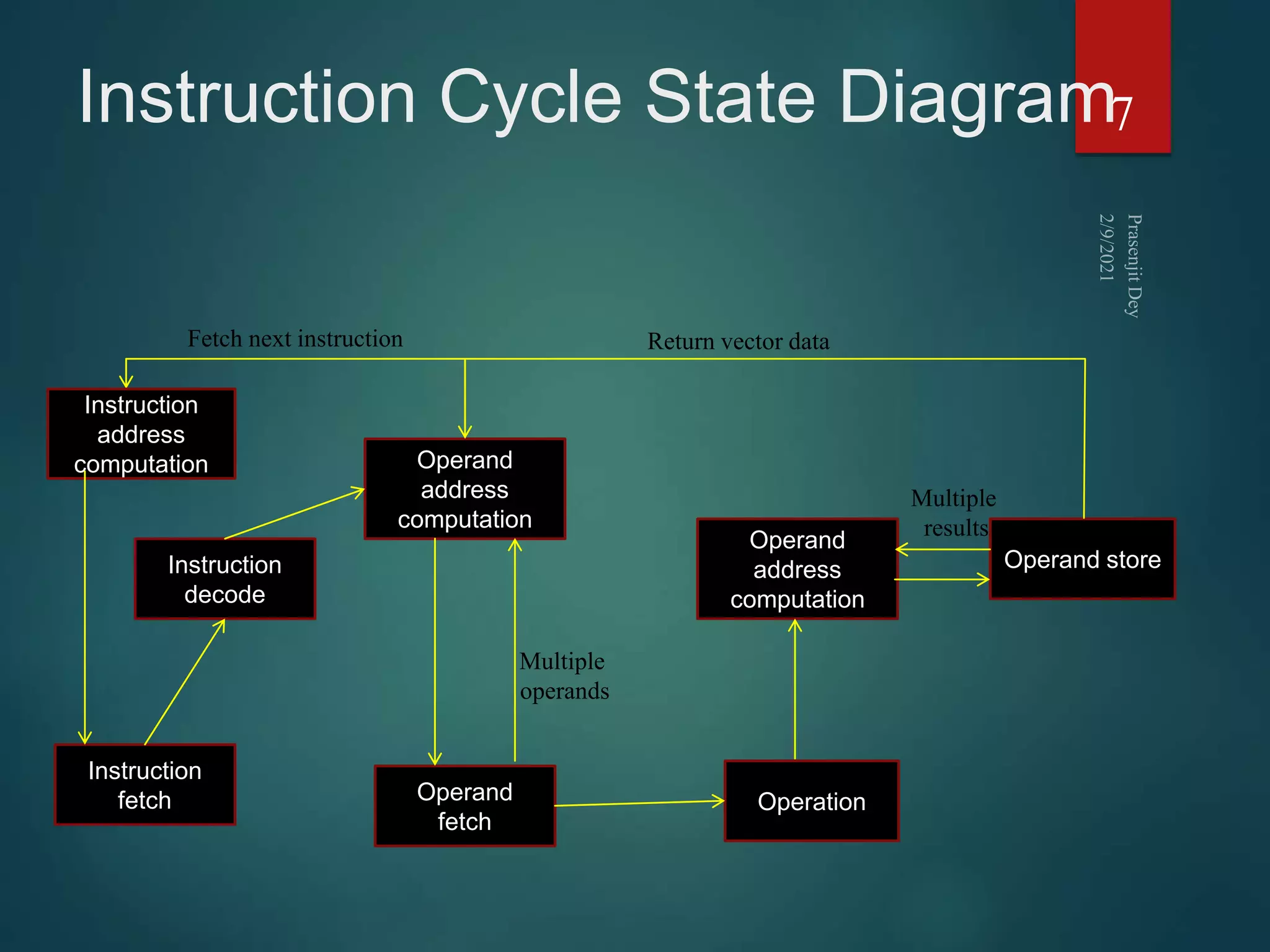
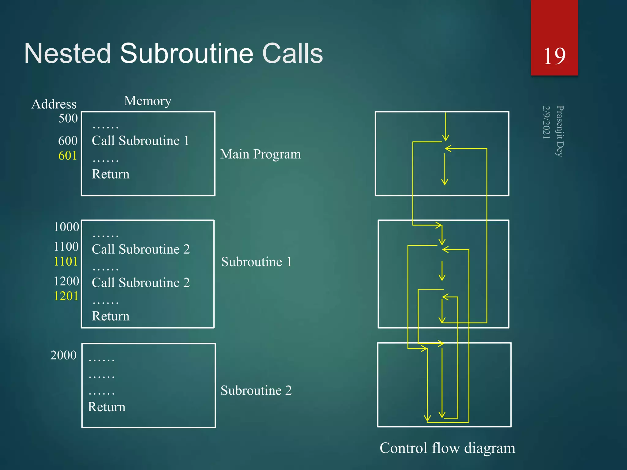
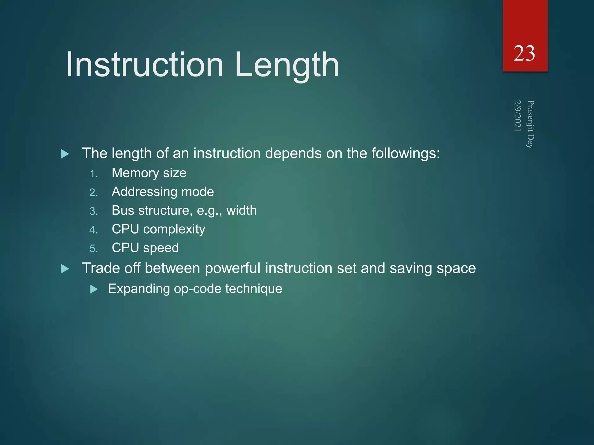
![3 address instruction
Needs very long words to hold everything
Not common
1. ADD F,A,B F A+B
2. MPY T,D,E T DxE
3. SUB T,T,C T T-C
4. DIV F,F,T F F/T
25
Op-code Result Operand 1 Operand 2
F = (A + B) / [(C - (D x E)]](https://image.slidesharecdn.com/instructionsetprasenjitdey-210209170748/75/Instruction-set-prasenjit-dey-25-2048.jpg)
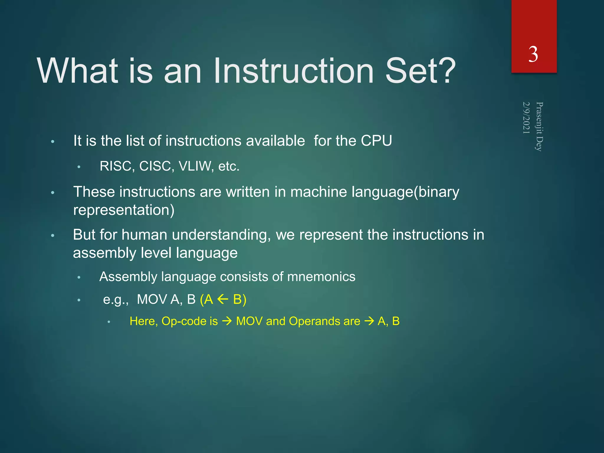
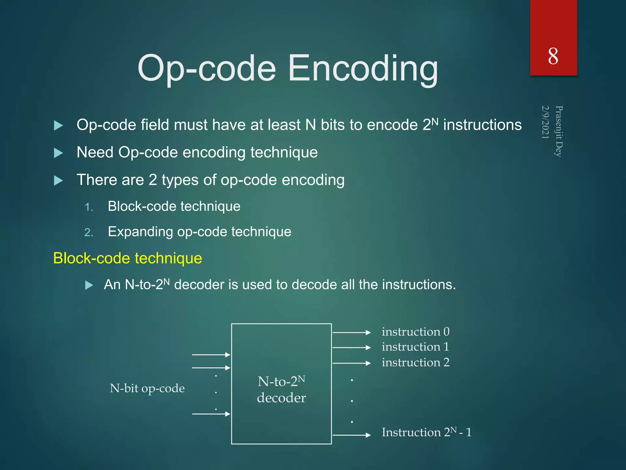
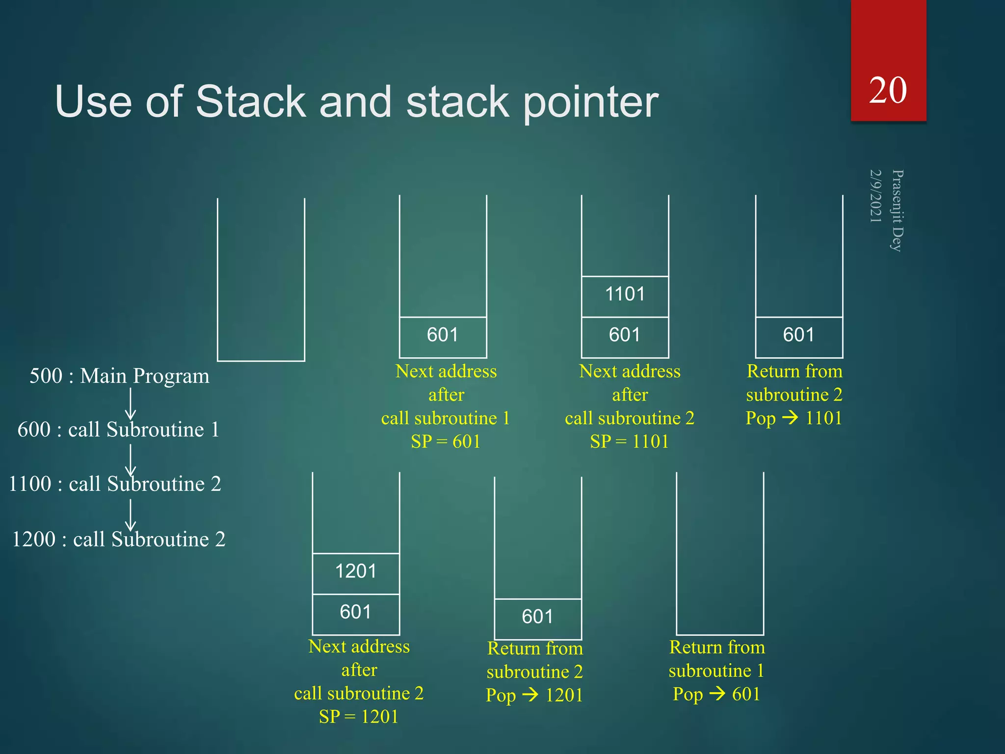
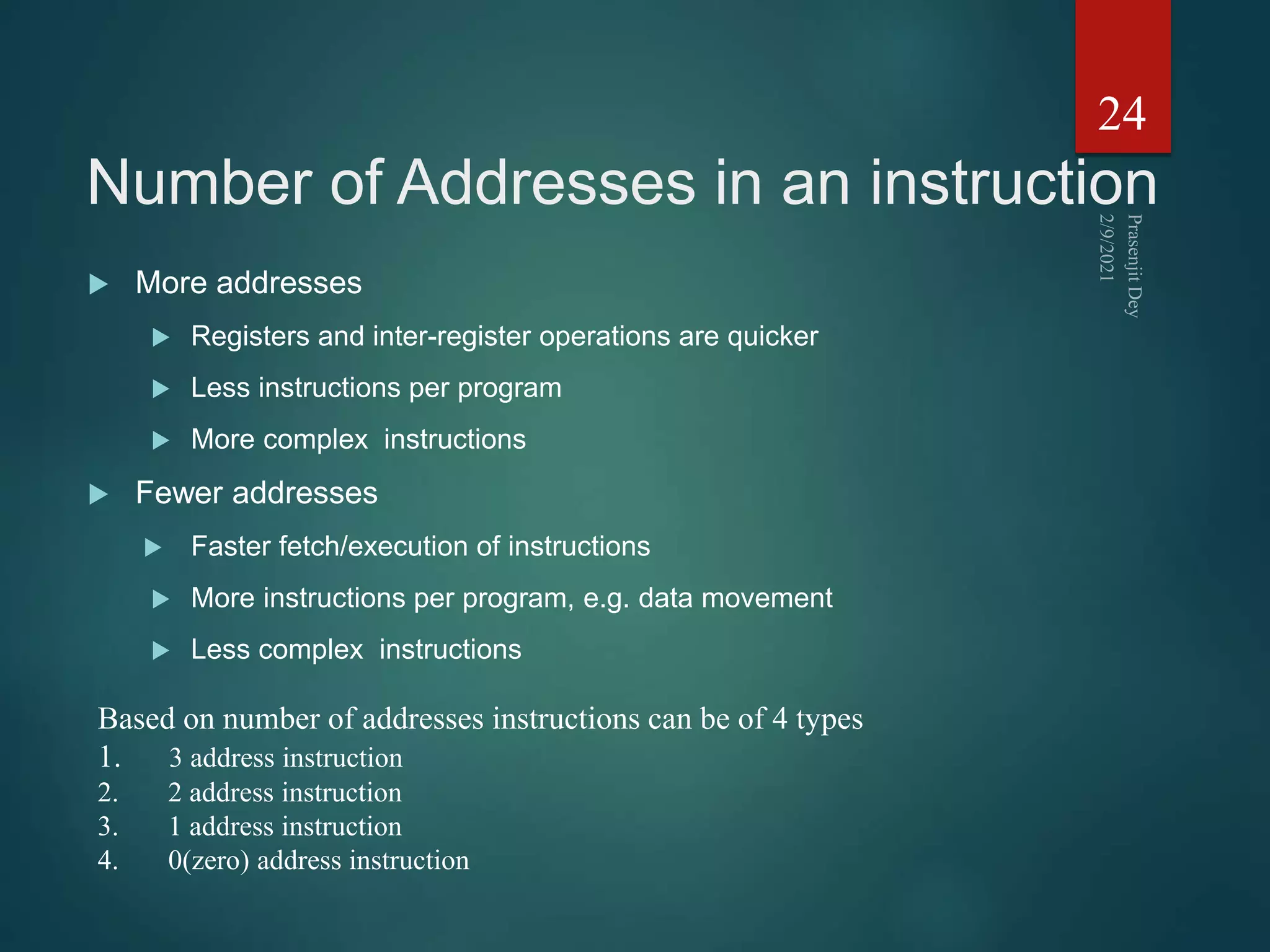
![2 address instruction
Reduces length of instruction
Requires extra work: temporary storage
1. MOVE F,A F A
2. ADD F,B F F+B
3. MOVE T,D T D
4. MPY T,E T TxE
5. SUB T,C T T-C
6. DIV F,T F F:T
26
Op-code Result Operand 1
F = (A + B) / [(C - (D x E)]](https://image.slidesharecdn.com/instructionsetprasenjitdey-210209170748/75/Instruction-set-prasenjit-dey-26-2048.jpg)
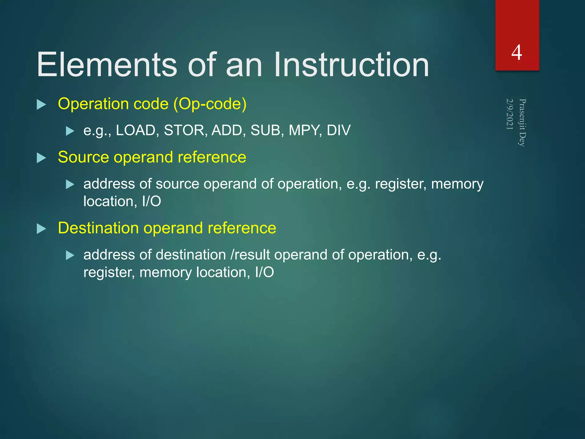
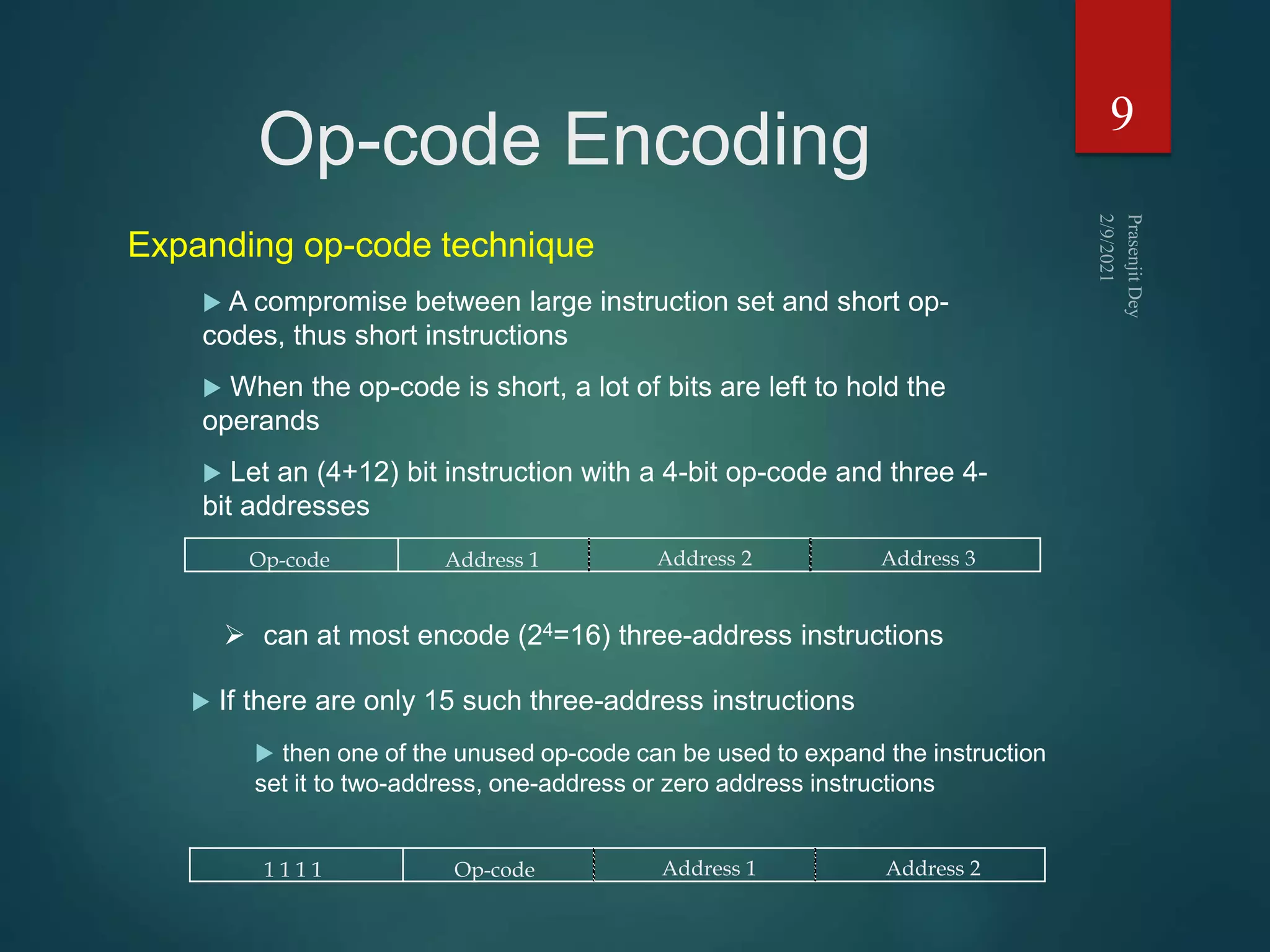
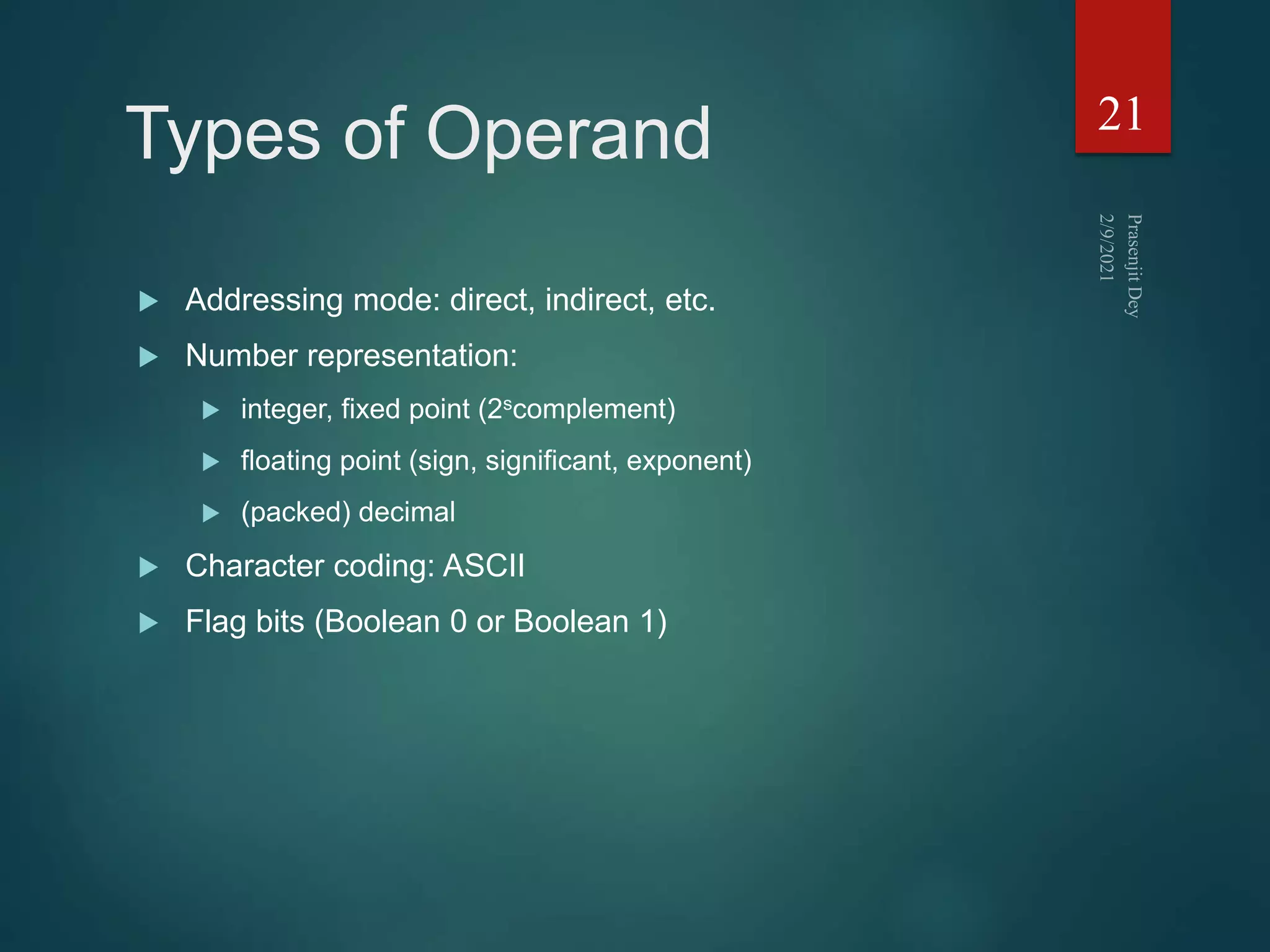
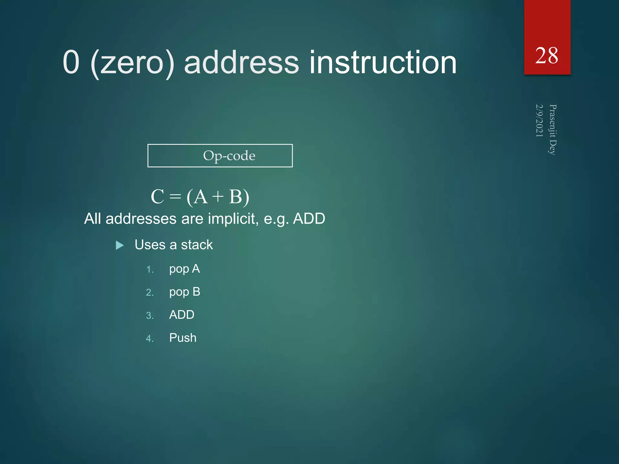
![1 address instruction
Implicit second address, usually a register (accumulator, AC)
1. LOAD D AC D
2. MPY E AC ACxE
3. SUB C AC AC-C
4. STOR F F AC
5. LOAD A AC A
6. ADD B AC AC+B
7. DIV F AC AC:F
8. STOR F F AC
27
Op-code Operand 1
F = (A + B) : [(C - (D x E)]](https://image.slidesharecdn.com/instructionsetprasenjitdey-210209170748/75/Instruction-set-prasenjit-dey-27-2048.jpg)

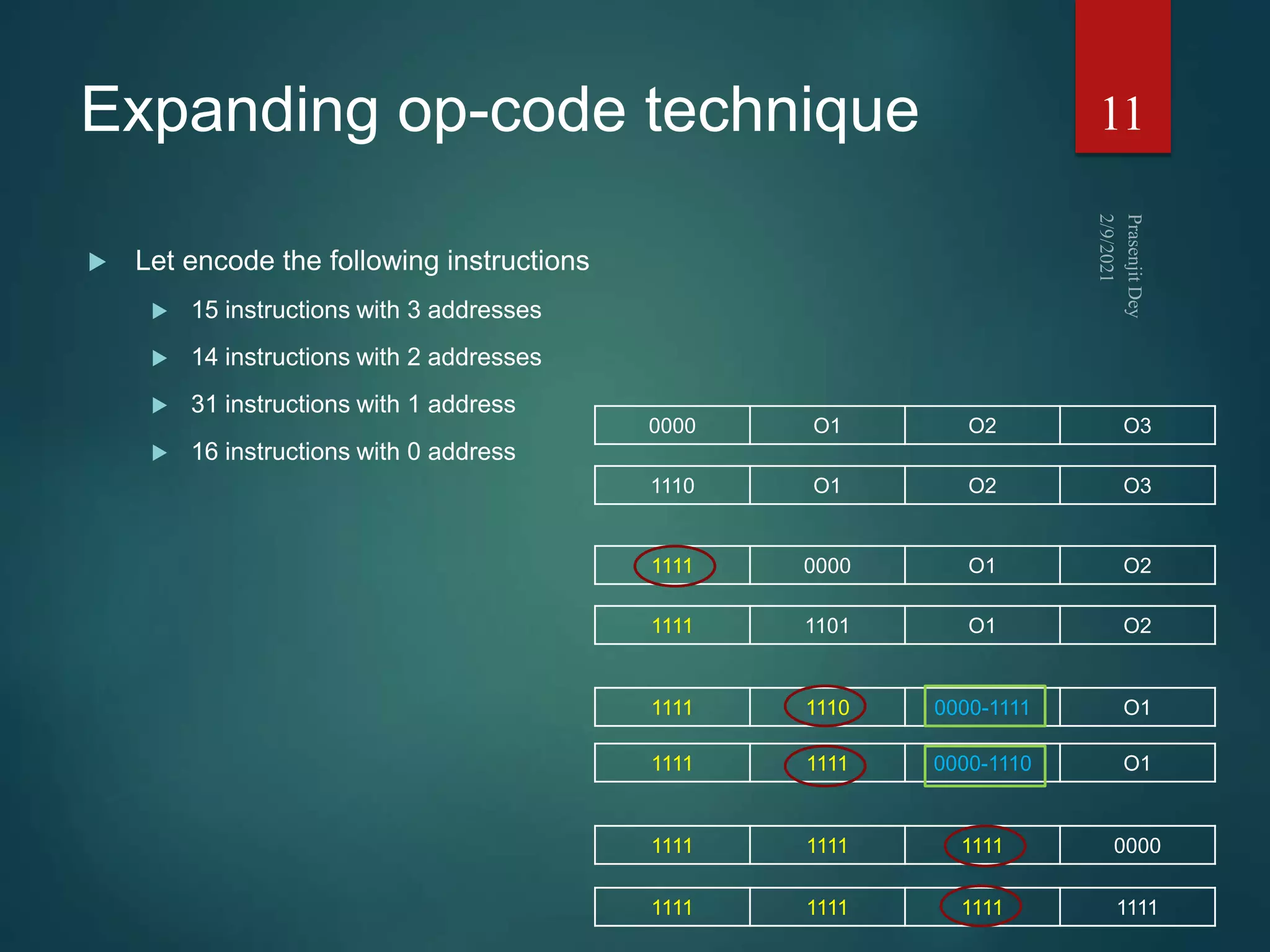
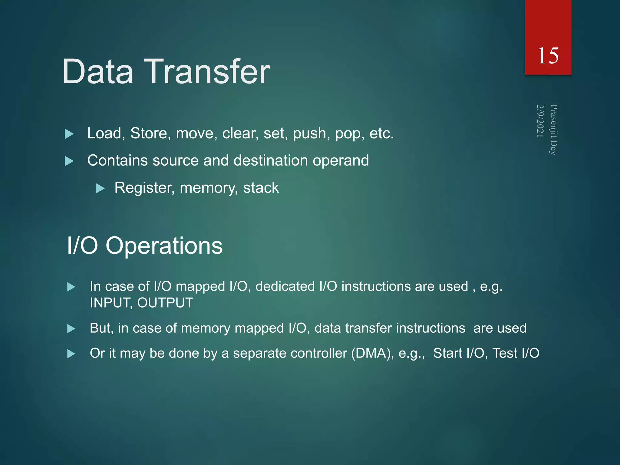
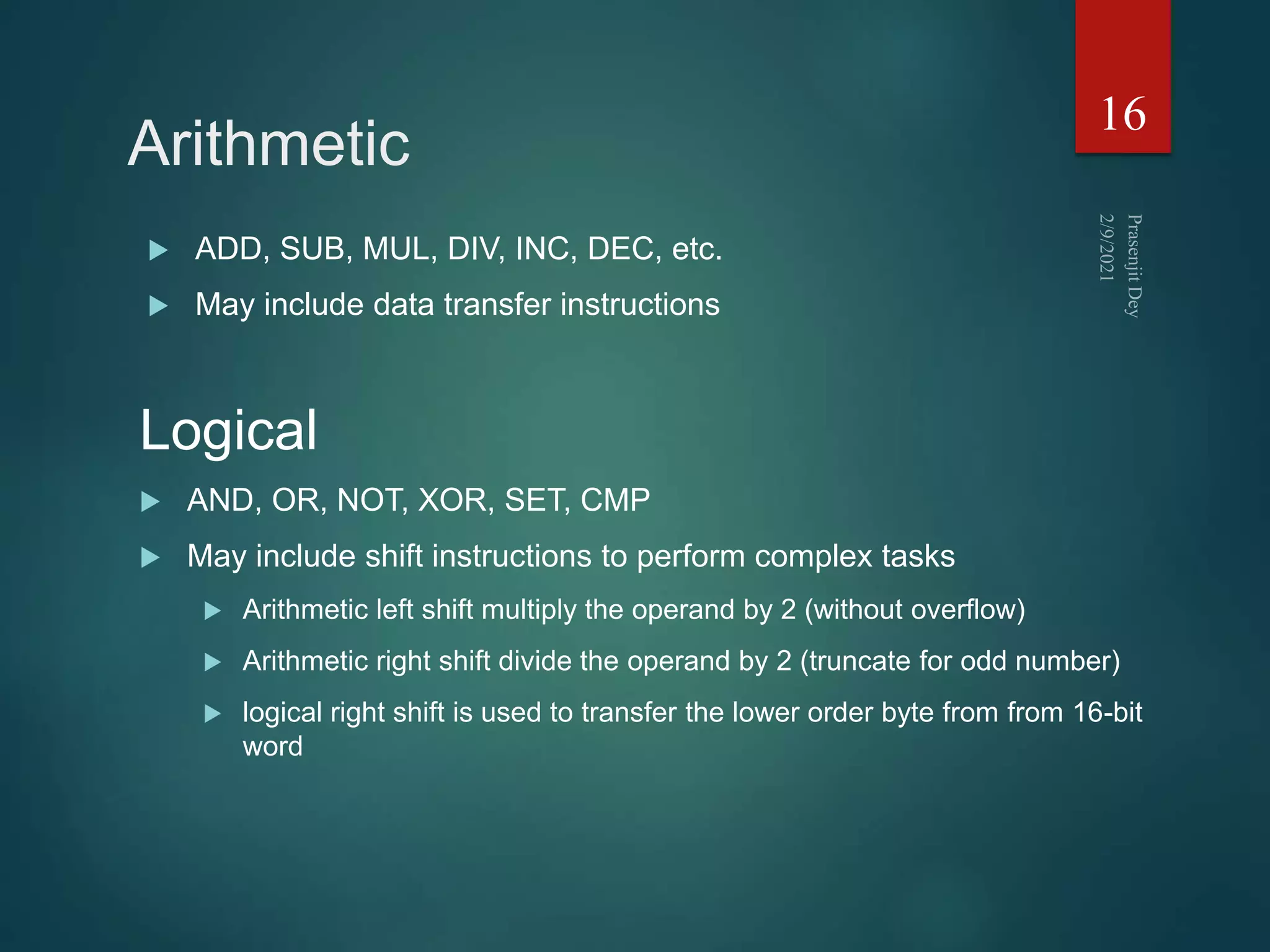
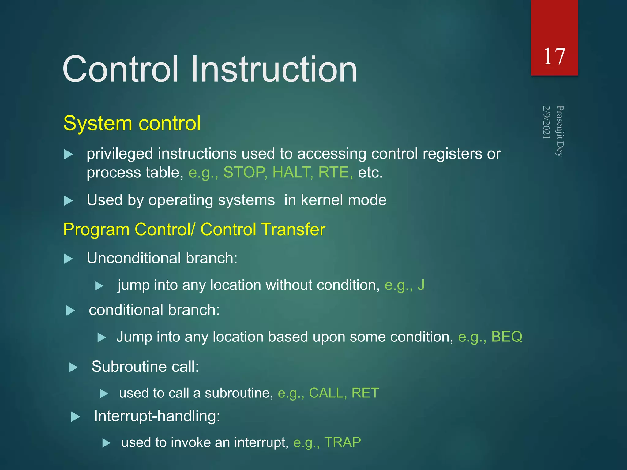
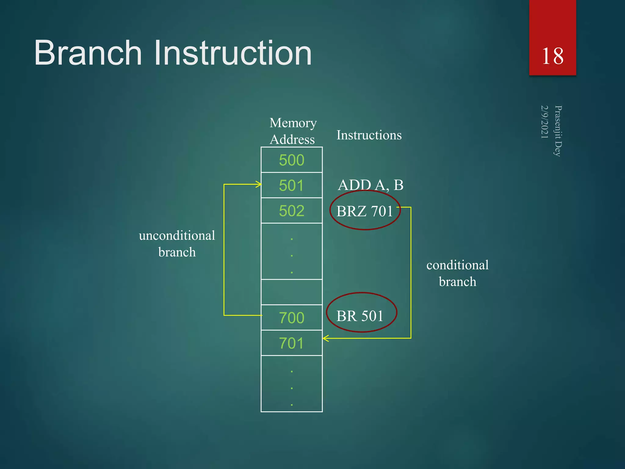
The document discusses instruction sets and their components. It defines an instruction set as the list of instructions available for the CPU, which are encoded in binary machine language or assembly language mnemonics. Each instruction contains an operation code and may include source and destination operand references. Instruction formats can vary in the number of operands from zero to three addresses. Instruction length, encoding techniques, and types of instructions like data transfer, arithmetic, and control instructions are also covered.