Download to read offline

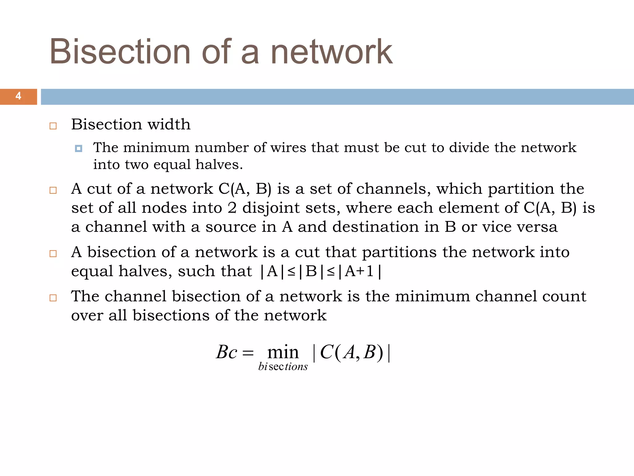
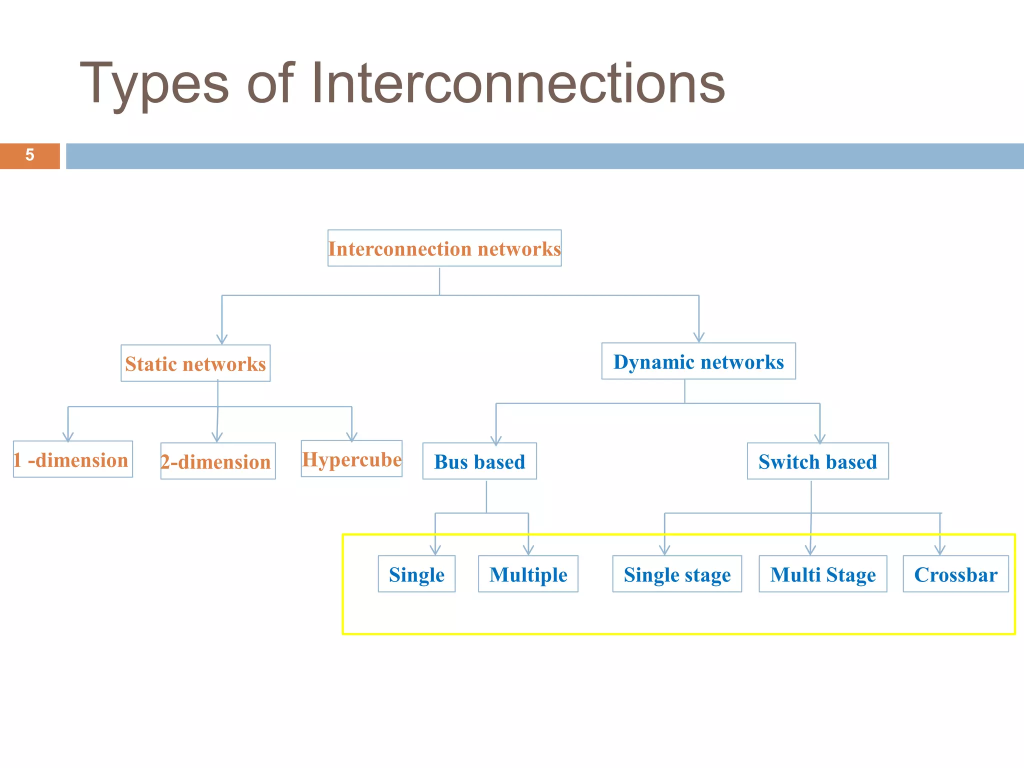

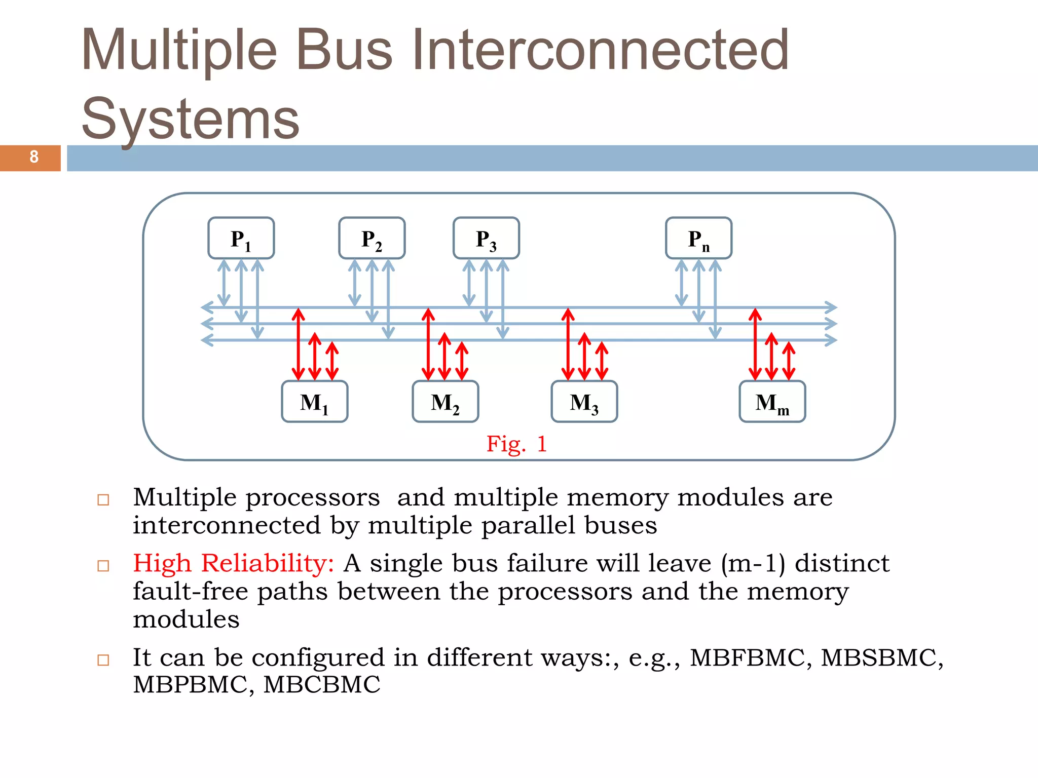
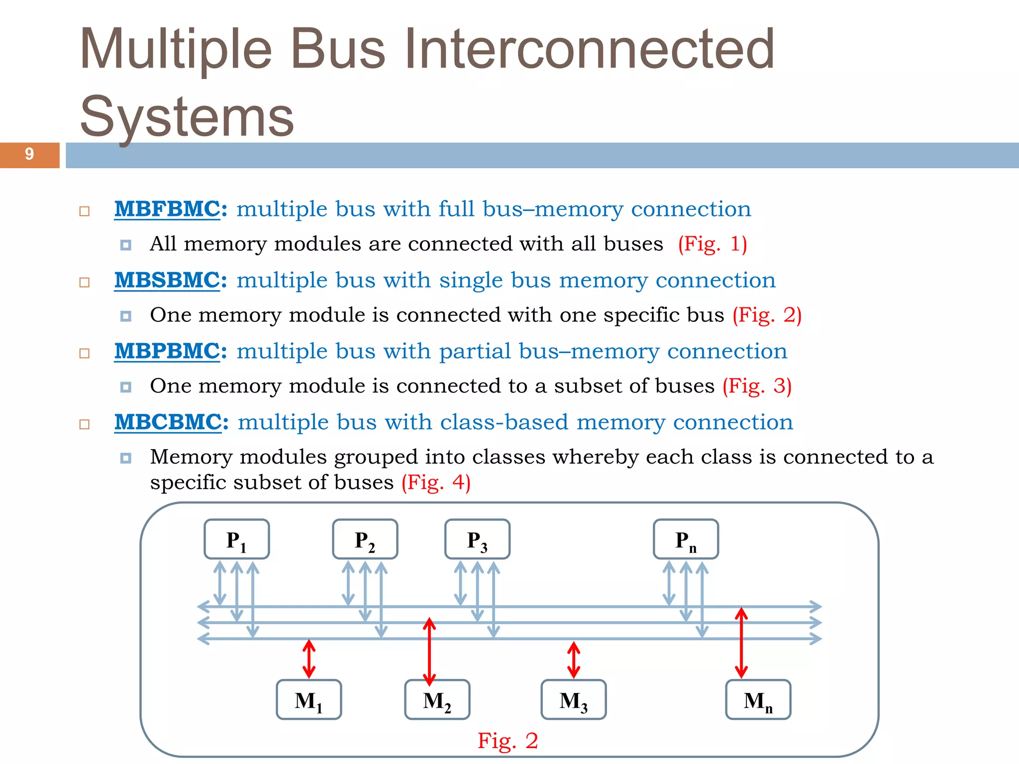

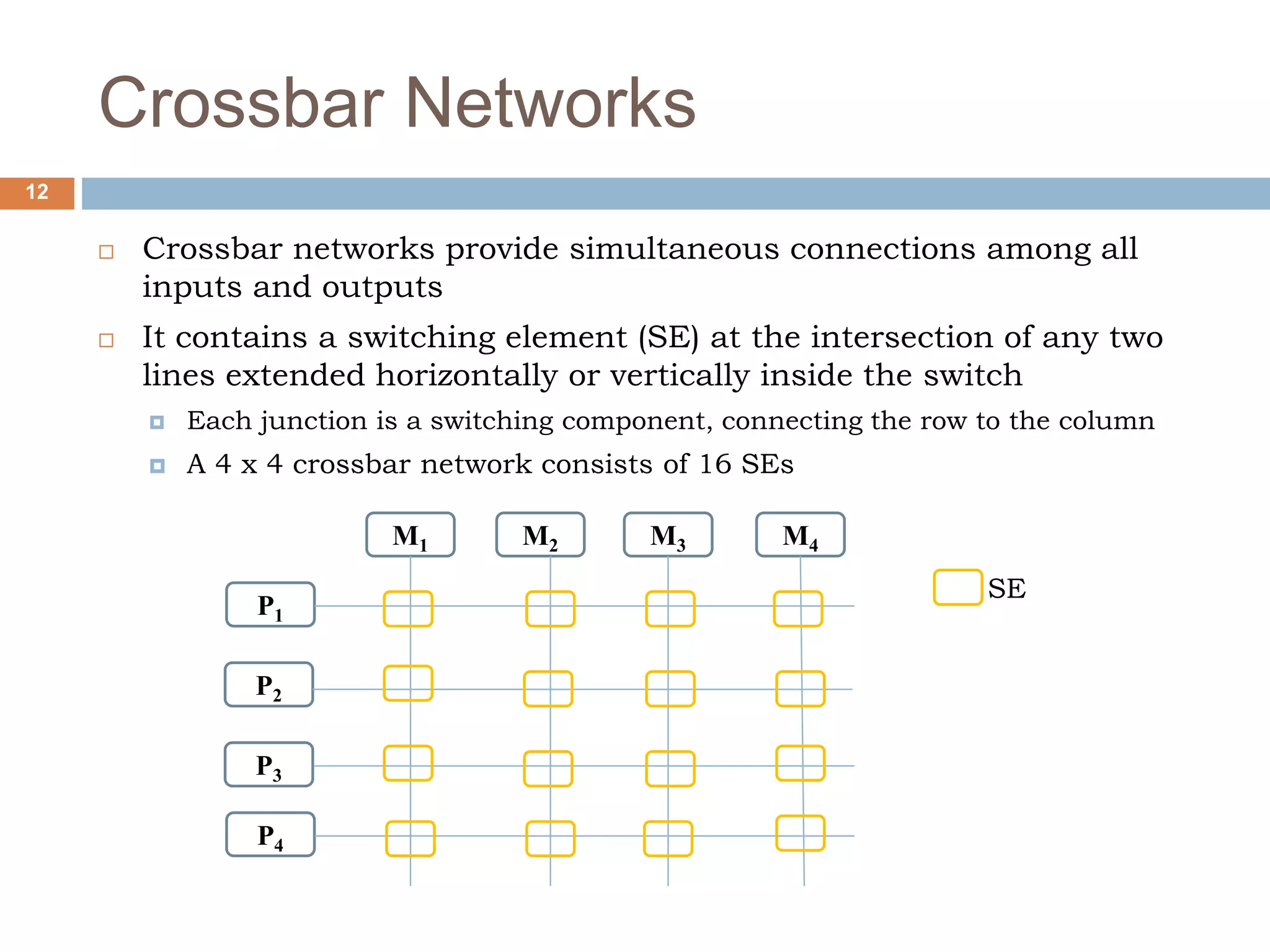
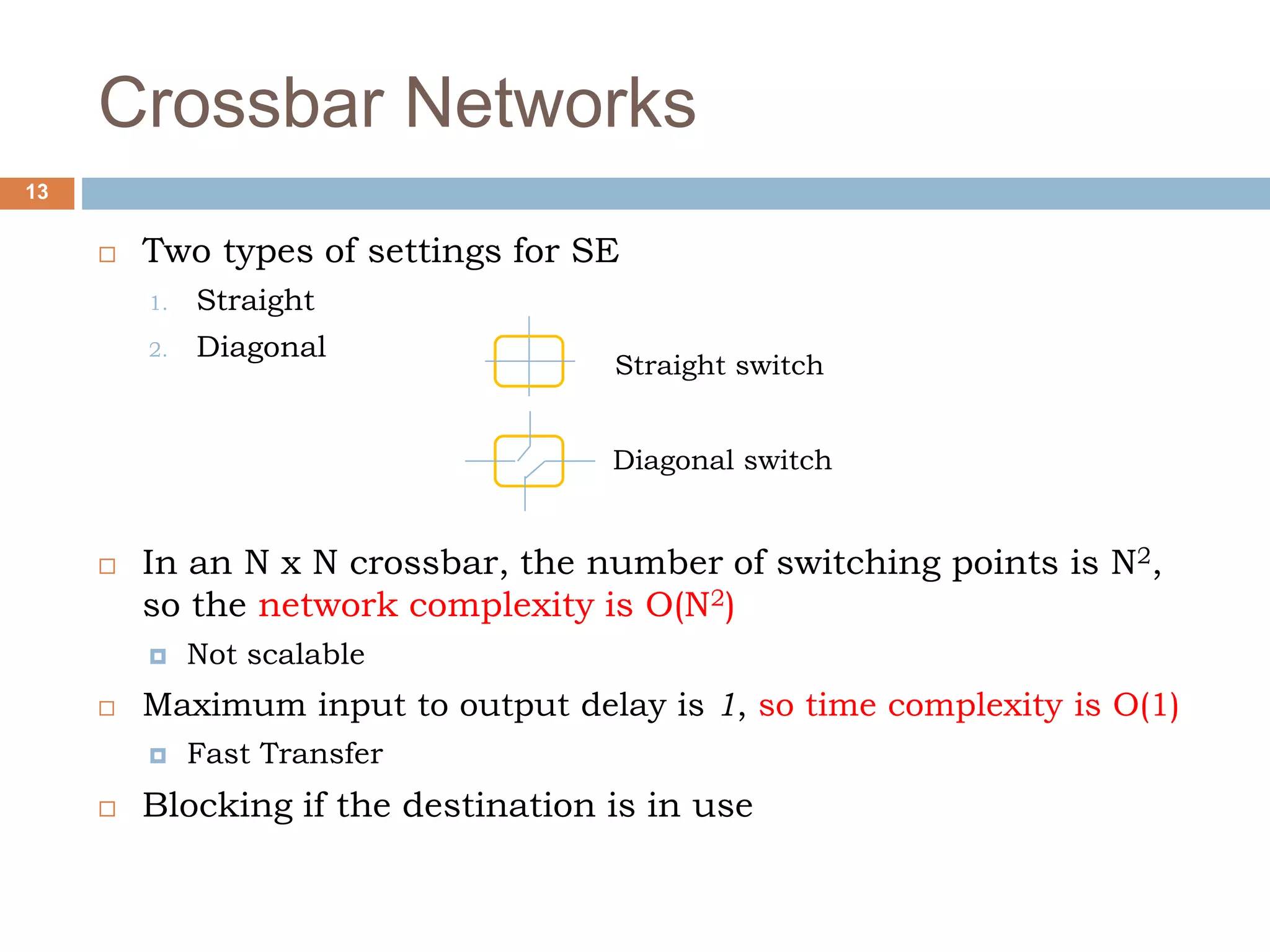


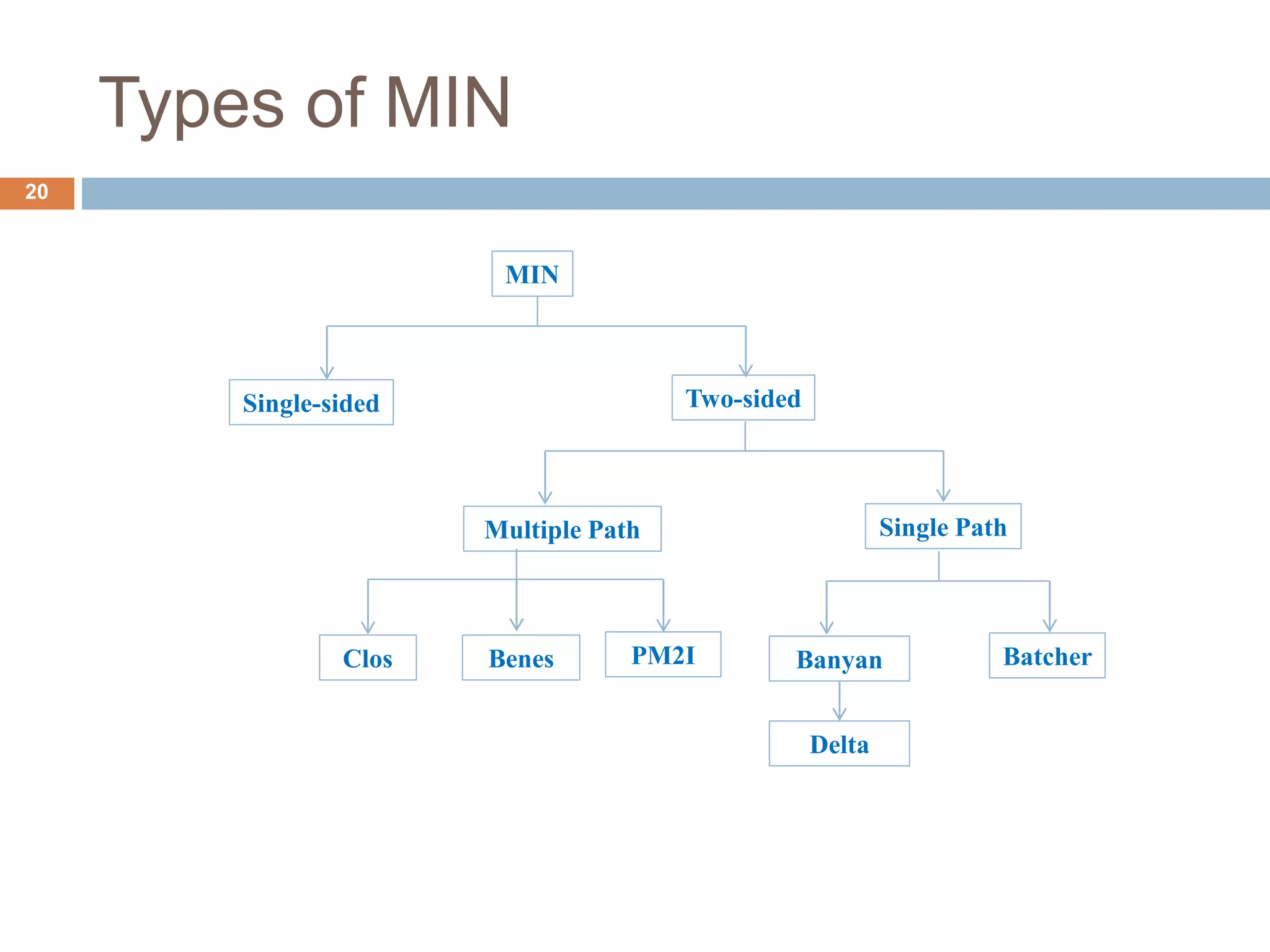


The document discusses dynamic interconnection networks which consist of multiple processors and memory modules connected in various ways, either statically or dynamically. It explains key concepts such as bisection width, types of interconnection networks—like static and dynamic, bus-based, and switch-based networks—and their associated complexities and latencies. Additionally, the document details configurations of bus networks, crossbar networks, single stage interconnection networks, and multistage networks, outlining their operational mechanics and comparative performances.