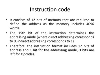
The document discusses computer instruction formats and addressing modes. It provides details on:
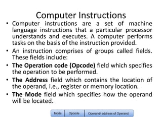
- Instruction codes contain operation codes and addresses to specify operations and memory/register locations.
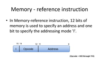
- There are two addressing modes - direct addressing uses the operand's address while indirect uses a pointer.
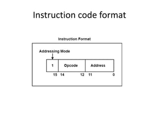
- A basic instruction format has 12 bits for the address, 1 bit for the mode, and 3 bits for the operation code.
- An instruction cycle has four phases - fetch, decode, read effective address, and execute the instruction.


![Instruction Format
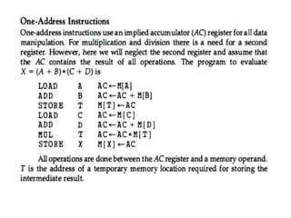
• An example of an accumulator-type organization instruction.
A D D X where X is the address of the operand.
• The ADD instruction in this case results in the operation AC <--
AC + M [X]. AC is the accumulator register and M [X]
symbolizes the memory word located at address X.
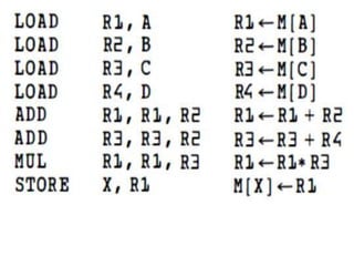
• An example of a general register type of organization was
presented in An example of register organization instruction.
• Thus the instruction for an arithmetic addition may be written
in an assembly language as ADD R 1 , R 2 , R 3 t o denote the
operation R 1 <--- R2 + R 3 .
• The number o f address fields in the instruction can be
reduced from three to two if the destination register is the
same as one of the source registers.](https://image.slidesharecdn.com/instructionformat-230903153754-82168d45/85/instruction-format-pptx-25-320.jpg)

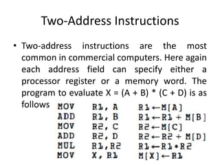
![Three-Address Instructions
• Computers with three-address instruction formats can use each
address field to specify either a processor register or a memory
operand.
• The program in assembly language that evaluates X = (A + B) *
(C + D) is shown below, together with comments that explain
the register transfer operation of each instruction.
• It is assumed that the computer has two processor registers, R 1
and R2.
• The symbol M [A ] denotes the operand at memory address
symbolized by A .](https://image.slidesharecdn.com/instructionformat-230903153754-82168d45/85/instruction-format-pptx-27-320.jpg)