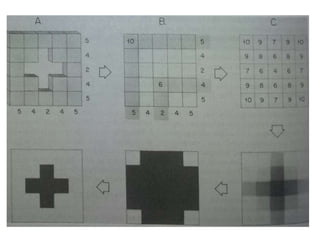
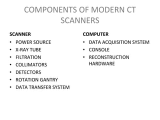
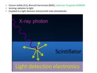
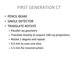
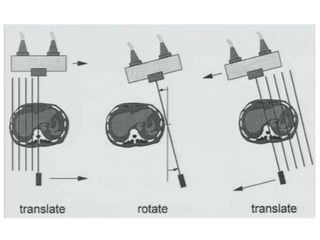
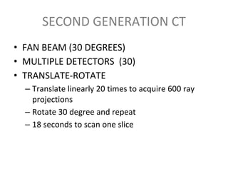
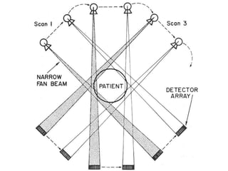
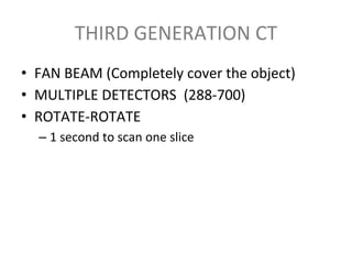
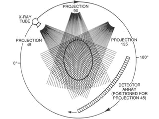
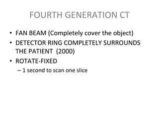
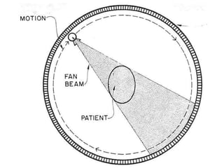
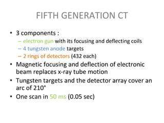
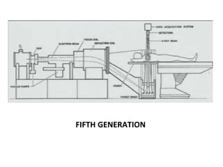
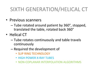
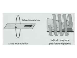
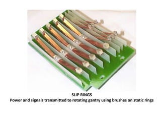
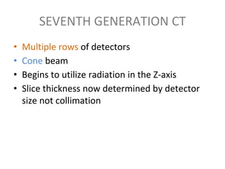
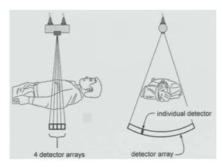
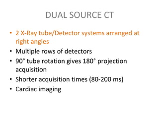
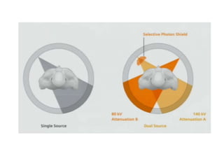
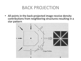
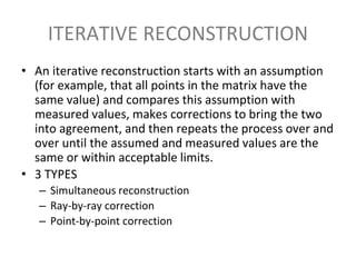
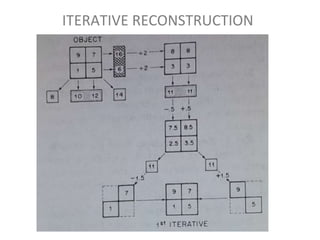
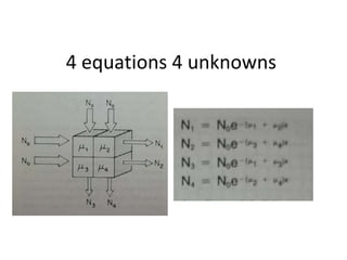
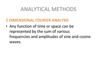
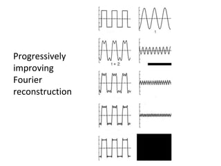
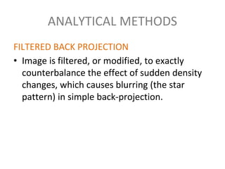
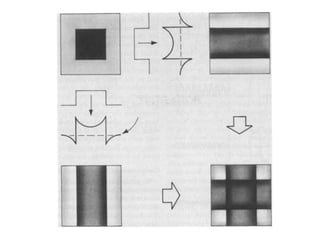
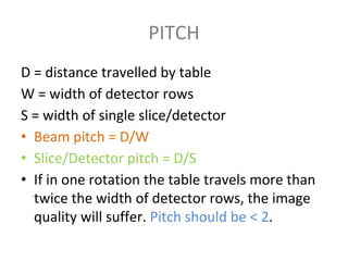
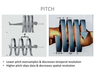
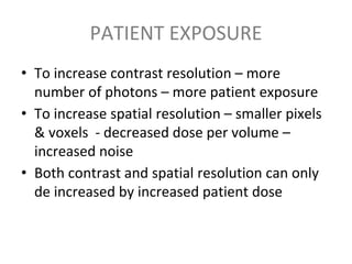
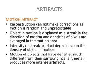
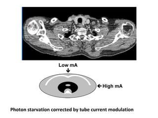
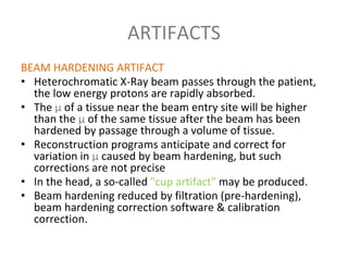
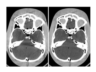
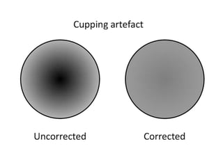
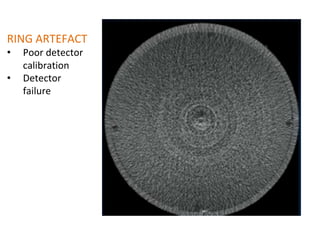
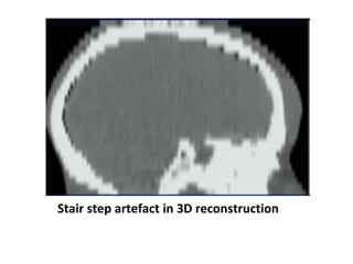
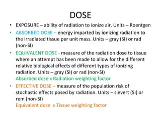
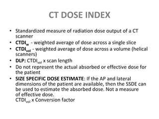
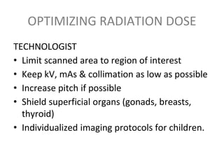
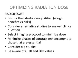
2. BASIC PRINCIPLE
The internal structure of an
object can be reconstructed
from multiple projections of the
object.
3.
4. COMPONENTS OF MODERN CT
SCANNERS
SCANNER
• POWER SOURCE
• X-RAY TUBE
• FILTRATION
• COLLIMATORS
• DETECTORS
• ROTATION GANTRY
• DATA TRANSFER SYSTEM
COMPUTER
• DATA ACQUISITION SYSTEM
• CONSOLE
• RECONSTRUCTION
HARDWARE
5.
6. X-RAY TUBE
• Rotating anode
• Large heat loading and heat dissipation
capacity
• 0.6 mm focal spot
10. COLLIMATION
• Shapes the beam in all 3
orthogonal planes
• Pre-patient collimation
– Reduces patient dose
• Post-patient collimation
– Reduces scatter
– Each detector has its
own collimator
– Decides slice thickness
(1,2,5, 10 mm)
11. DETECTORS
• Most expensive components of the CT system
• 2 types
– Gas-filled Ionization Chambers
– Scintillation crystals
12. • 2 Electrodes with a potential difference
• Inert gas (Xenon) – Dense, Compressed, Long chamber (10 cm)
• Current produced proportional to intensity of X-rays entering the chamber
13. • Cesium Iodide (CsI), Bismuth Germinate (BGO), Cadmium Tungstate (CdWO4)
• Ionizing radiation to light
• Coupled to a light detector (silicon/solid state photodiode)
14. FIRST GENERATION CT
• PENCIL BEAM
• SINGLE DETECTOR
• TRANSLATE-ROTATE
– Parallel ray geometry
– Translate linearly to acquire 160 ray projections
– Rotate 1 degree and repeat
– 4.5 min to scan one slice
– 1.5 min for reconstruction
15.
16. SECOND GENERATION CT
• FAN BEAM (30 DEGREES)
• MULTIPLE DETECTORS (30)
• TRANSLATE-ROTATE
– Translate linearly 20 times to acquire 600 ray
projections
– Rotate 30 degree and repeat
– 18 seconds to scan one slice
17.
18. THIRD GENERATION CT
• FAN BEAM (Completely cover the object)
• MULTIPLE DETECTORS (288-700)
• ROTATE-ROTATE
– 1 second to scan one slice
19.
20. FOURTH GENERATION CT
• FAN BEAM (Completely cover the object)
• DETECTOR RING COMPLETELY SURROUNDS
THE PATIENT (2000)
• ROTATE-FIXED
– 1 second to scan one slice
21.
22. FIFTH GENERATION CT
• 3 components :
– electron gun with its focusing and deflecting coils
– 4 tungsten anode targets
– 2 rings of detectors (432 each)
• Magnetic focusing and deflection of electronic
beam replaces x-ray tube motion
• Tungsten targets and the detector array cover an
arc of 210°
• One scan in 50 ms (0.05 sec)
24. SIXTH GENERATION/HELICAL CT
• Previous scanners
– Tube rotated around patient by 360°, stopped,
translated the table, rotated back 360°
• Helical CT
– Tube rotates continuously and table travels
continuously
– Required the development of
• SLIP RING TECHNOLOGY
• HIGH POWER X-RAY TUBES
• NON-COPLANAR INTERPOLATION ALGORITHMS
25.
26.
27. SLIP RINGS
Power and signals transmitted to rotating gantry using brushes on static rings
28. SEVENTH GENERATION CT
• Multiple rows of detectors
• Cone beam
• Begins to utilize radiation in the Z-axis
• Slice thickness now determined by detector
size not collimation
29.
30. DUAL SOURCE CT
• 2 X-Ray tube/Detector systems arranged at
right angles
• Multiple rows of detectors
• 90° tube rotation gives 180° projection
acquisition
• Shorter acquisition times (80-200 ms)
• Cardiac imaging
36. LINEAR ATTENUATION COEFFICIENT
(µ)
• Intensity of x-ray beams decreases
exponentially as it passes through matter
• µ depends on photon energy, atomic number
& physical density of the material
37. HOUNSFIELD UNIT (HU)
• Normalized (wrt water) unit of linear
attenuation
• HU of water is 0
• HU of vacuum is -1000
38. WINDOWING
• WIDTH AND CENTER
• Principles
– Wide width for inherent contrasted tissues
– Narrow width when you need more contrast
– Centring on tissue of interest
• 400 window at 30 center
– <-170 black; >230 white
• Brain window - W80:C35
• Subdural window – W200:C70
39. RECONSTRUCTION ALGORITHMS
• BACK PROJECTION
• ITERATIVE RECONSTRUCTION
• ANALYTICAL METHODS
– 2D Fourier analysis
– Filtered back projection
40. BACK PROJECTION
• Summation method
• Superimposed projections
• Background density remains as noise to
deteriorate image quality
42. BACK PROJECTION
• All points in the back-projected image receive density
contributions from neighboring structures resulting in a
star pattern
43. ITERATIVE RECONSTRUCTION
• An iterative reconstruction starts with an assumption
(for example, that all points in the matrix have the
same value) and compares this assumption with
measured values, makes corrections to bring the two
into agreement, and then repeats the process over and
over until the assumed and measured values are the
same or within acceptable limits.
• 3 TYPES
– Simultaneous reconstruction
– Ray-by-ray correction
– Point-by-point correction
46. ANALYTICAL METHODS
2 DIMENSIONAL FOURIER ANALYSIS
• Any function of time or space can be
represented by the sum of various
frequencies and amplitudes of sine and cosine
waves.
48. ANALYTICAL METHODS
FILTERED BACK PROJECTION
• Image is filtered, or modified, to exactly
counterbalance the effect of sudden density
changes, which causes blurring (the star
pattern) in simple back-projection.
51. QUANTUM MOTTLE (NOISE)
• Deviation from uniformity representing
statistical fluctuations in the emission of
photons
• Variation in the number of photons absorbed
by the detector
• Only way to decrease noise is increase the
number of photons (increased patient dose)
• Accurate mathematical reconstruction makes
mottle more visible
52.
53. RESOLUTION
• SPATIAL RESOLUTION
– Ability to display, as separate distinct images, 2 objects that are
very close to each other
– Depends upon:
• Scanner design – X-Ray tube focal spot, detector size, magnification
• Computer reconstruction
• Display
• CONTRAST RESOLUTION
– Ability to display, as separate distinct images, areas that differ in
density by a small amount
– object must produce enough change in the number of
transmitted photons to overcome statistical fluctuations in
transmitted photons caused by noise.
– Modern CT scanners resolve density differences of 0.5% or less
54. PITCH
D = distance travelled by table
W = width of detector rows
S = width of single slice/detector
• Beam pitch = D/W
• Slice/Detector pitch = D/S
• If in one rotation the table travels more than
twice the width of detector rows, the image
quality will suffer. Pitch should be < 2.
56. PATIENT EXPOSURE
• To increase contrast resolution – more
number of photons – more patient exposure
• To increase spatial resolution – smaller pixels
& voxels - decreased dose per volume –
increased noise
• Both contrast and spatial resolution can only
de increased by increased patient dose
57. ARTIFACTS
MOTION ARTIFACT
• Reconstruction can not make corrections as
motion is random and unpredictable
• Object in motion is displayed as a streak in the
direction of motion and densities of pixels are
averaged in the motion area
• Intensity of streak artefact depends upon the
density of object in motion
• Motion of objects that have densities much
different from their surroundings (air, metal)
produces more intense artefacts.
59. ARTIFACTS
STREAK ARTIFACT
• One of the basic assumptions in CT scanning is
that each detector, at every position, will
observe some transmitted radiation. If a high
density material severely reduces the
transmission, the detector may record no
transmission. This violates the basic
assumption, and the reconstruction program
will not account for such a violation.
60. Streak artifact produced by a shotgun pellet (B). Scout film (A) shows location of pellet
(arrow)
63. ARTIFACTS
BEAM HARDENING ARTIFACT
• Heterochromatic X-Ray beam passes through the patient,
the low energy protons are rapidly absorbed.
• The µ of a tissue near the beam entry site will be higher
than the µ of the same tissue after the beam has been
hardened by passage through a volume of tissue.
• Reconstruction programs anticipate and correct for
variation in µ caused by beam hardening, but such
corrections are not precise
• In the head, a so-called "cup artifact" may be produced.
• Beam hardening reduced by filtration (pre-hardening),
beam hardening correction software & calibration
correction.
68. DOSE
• EXPOSURE – ability of radiation to ionize air. Units – Roentgen
• ABSORBED DOSE – energy imparted by ionizing radiation to
the irradiated tissue per unit mass. Units – gray (SI) or rad
(non-SI)
• EQUIVALENT DOSE - measure of the radiation dose to tissue
where an attempt has been made to allow for the different
relative biological effects of different types of ionizing
radiation. Units – gray (SI) or rad (non-SI)
Absorbed dose x Radiation weighting factor
• EFFECTIVE DOSE – measure of the population risk of
stochastic effects posed by radiation. Units – sievert (SI) or
rem (non-SI)
Equivalent dose x Tissue weighting factor
69. CT DOSE INDEX
• Standardized measure of radiation dose output of a CT
scanner
• CTDIw - weighted average of dose across a single slice
• CTDIvol - weighted average of dose across a volume (helical
scanners)
• DLP: CTDIvol x scan length
• Do not represent the actual absorbed or effective dose for
the patient
• SIZE SPECIFIC DOSE ESTIMATE: If the AP and lateral
dimensions of the patient are available, then the SSDE can
be used to estimate the absorbed dose. Not a measure
of effective dose.
CTDIvol x Conversion factor
70. OPTIMIZING RADIATION DOSE
TECHNOLOGIST
• Limit scanned area to region of interest
• Keep kV, mAs & collimation as low as possible
• Increase pitch if possible
• Shield superficial organs (gonads, breasts,
thyroid)
• Individualized imaging protocols for children.
71. OPTIMIZING RADIATION DOSE
RADIOLOGIST
• Ensure that studies are justified (weigh
benefits vs risks)
• Consider alternative studies to answer clinical
question
• Select imaging protocol to minimize dose
• Minimize phases of contrast enhancement to
those that are essential
• Consider old studies
• Be aware of CTDI and DLP values
72. REFERENCES
• Christensen’s Physics of Diagnostic Radiology 4E;
Chapter 19 Pages 289-322
• Grainger and Allison’s Diagnostic Radiology 6E;
Chapter 4 Pages 76-90
• Julia F. Barrett et al. Artifacts in CT: Recognition
and Avoidance, RadioGraphics. 2004; 24
• The AAPM/RSNA Physics Tutorial for Residents:
Search for Isotropic Resolution in CT from
Conventional through Multiple-Row Detector,
RadioGraphics. 2002; 22