The presentation discusses the components and functioning of x-ray generators, including circuits, exposure timers, and different types of transformers. It emphasizes the role of transformers in voltage management, the mechanics of rectifiers in converting AC to DC, and the efficiency considerations of these systems. Additionally, it covers exposure timer types and automatic exposure control systems to ensure accurate x-ray exposure levels.

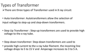
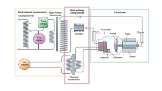
![The High Voltage Transformer
• Has a step up ratio of 1000: 1 [Ns/Np]
• Current flows in 1 A to 1mA.
• Converts voltage to kilovoltage.](https://image.slidesharecdn.com/xraygeneratorcircuits-180206133417/85/X-ray-generator-circuits-14-320.jpg)


![Portable and mobile radiographic equipments [Autosaved].pptx](https://cdn.slidesharecdn.com/ss_thumbnails/portableandmobileradiographicequipmentsautosaved-230729155829-aadaaabd-thumbnail.jpg?width=640&height=640&fit=bounds)


