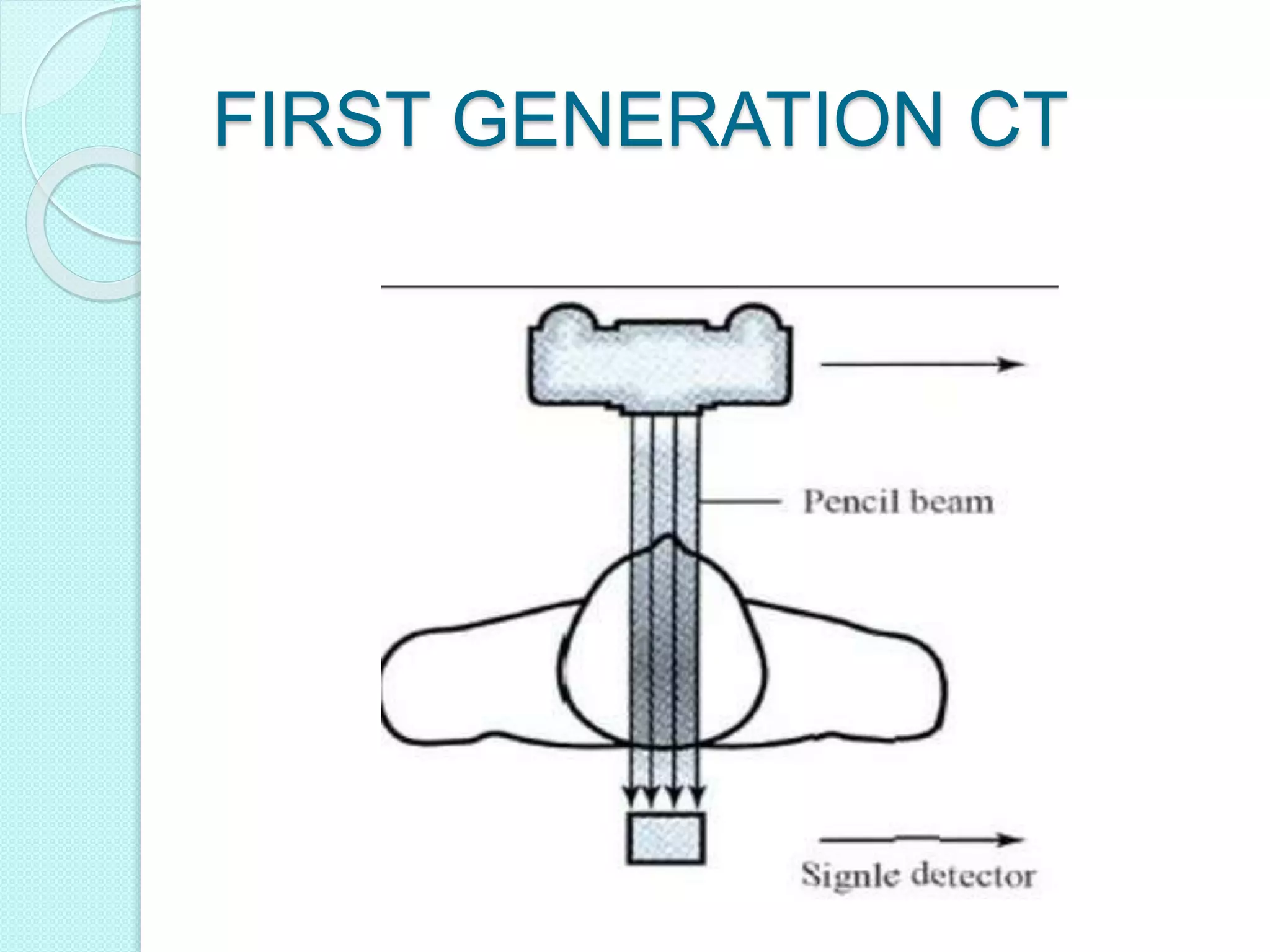
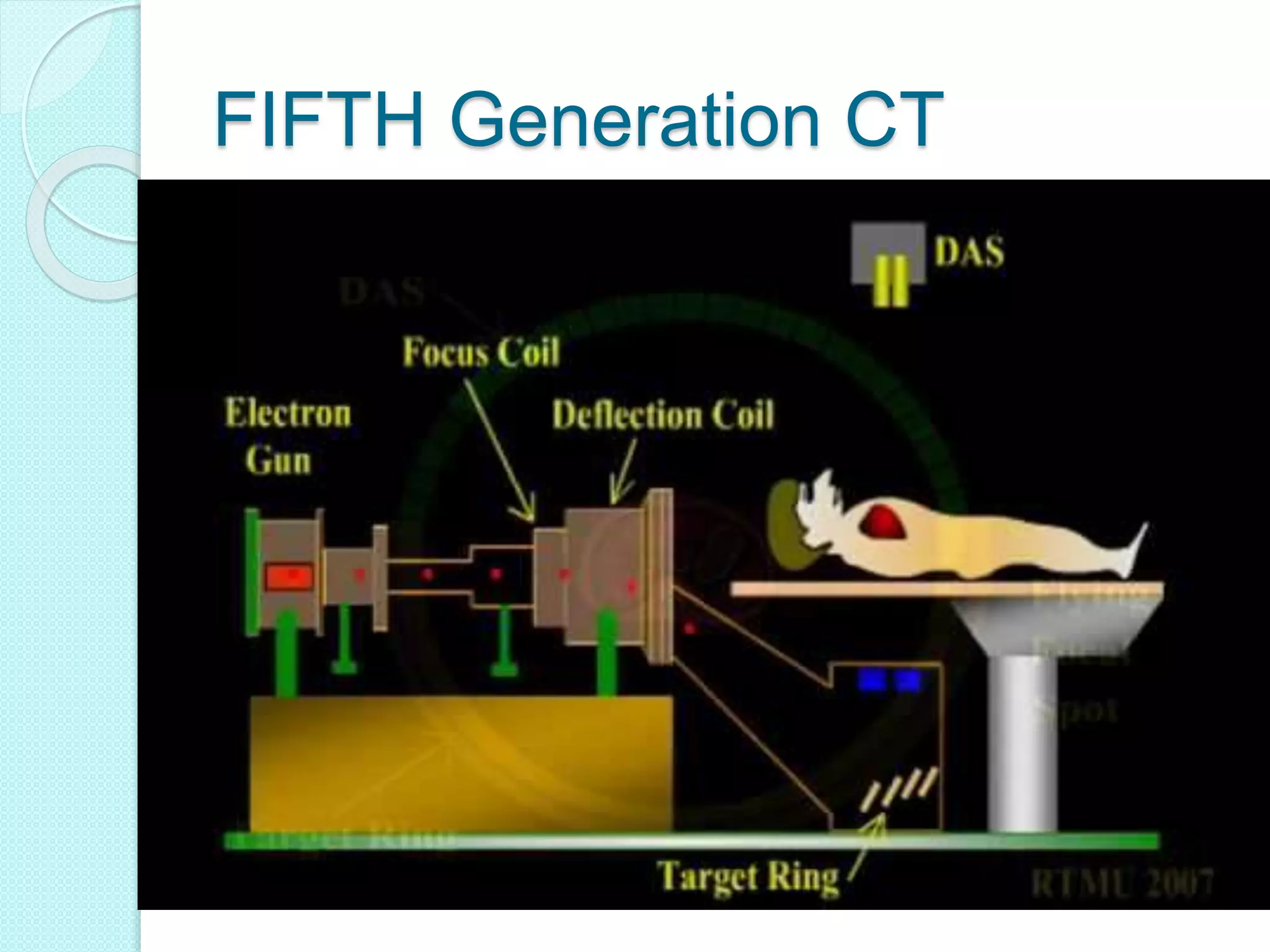
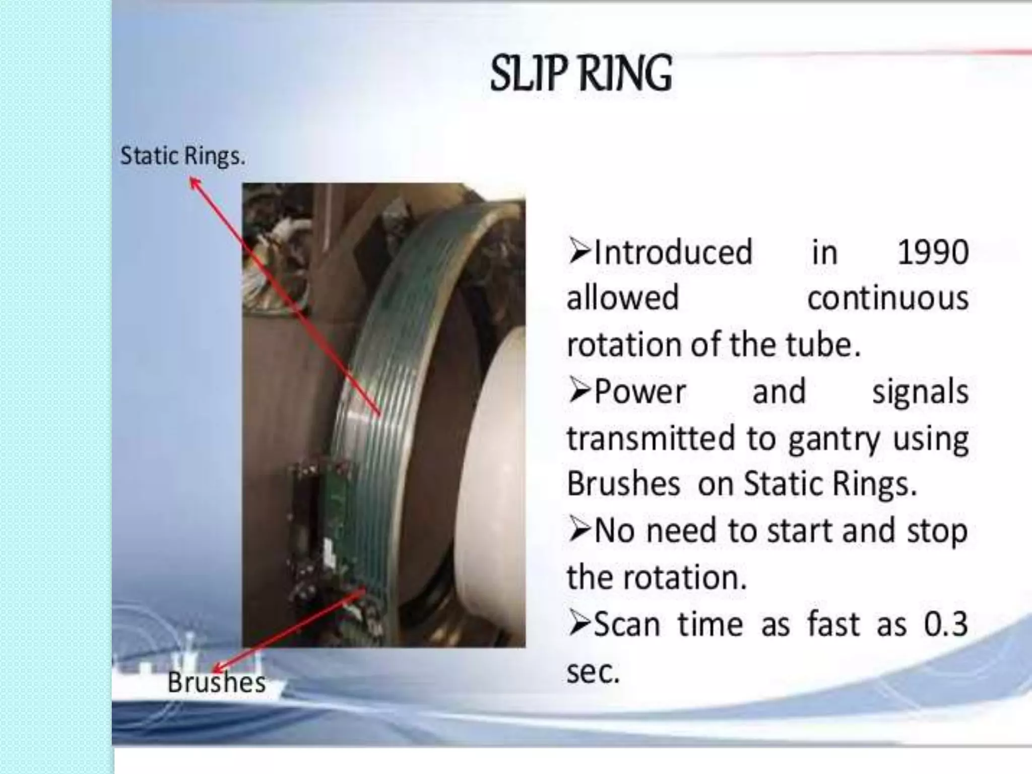
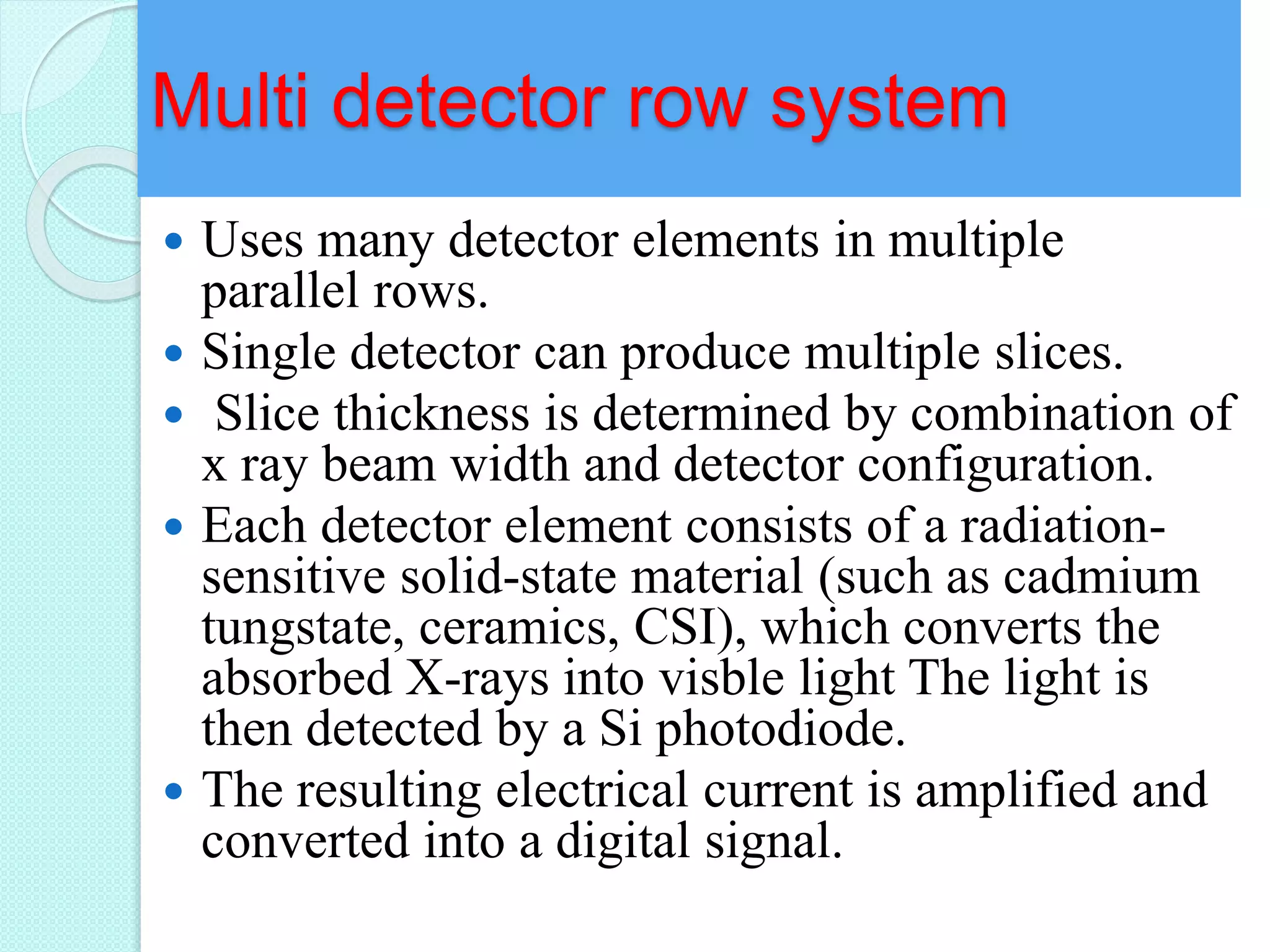
Presented by Moderator
Sujan Poudel Mr. Mukesh Kr. Jha
B.Sc. MIT 2015 Demonstrator
Department of Radio-
diagnosis and imaging
B.P Koirala Institute of Health Sciences
Dharan
Computed Tomography
Introduction
 Word tomography literally means ‘tomo’
meaning to cut, section , ‘graphy’ meaning
drawing. In case of CT a sophisticated
computerized method is used to obtain data and
transfer them into cross sectional slice of human
body.
 Earlier scanner produced only axial cuts so it was
called computerized axial tomography (CAT) scan.
 CT combines rotating X radiation and radiation
sensitive detectors coupled with a computer to
create cross sectional image of any part of the
body.
ADVANTAGE OF COMPUTED
TOMOGRAPHY OVER
CONVENTIONAL RADIOGRAPHY
 To overcome superimposition of structures.
 Ability to distinguish between two tissue with
similar density. i.e. it have higher contrast
resolution.
 For an object to be visible on image produced
from screen film radiography it must have a
least 5% difference in contrast from its
background material whereas for CT it is 0.5%
 In CT 1% contrast difference correspond to
difference of 10 HU.
PRINCIPLE OF TOMOGRAPHY
 The internal structure of the object can be reconstructed
from multiple projections of the object.
 A source of ionizing radiation is transmitted
through an object to recreate an image of
the object based on its x-ray absorption.
 I=IOe-μx
 Attenuation depend on Atomic number and density of
material so linear attenuation coefficient will be higher
for bone than soft tissue.
 Difference in linear attenuation are responsible for
contrast of CT image.
 To produce image, attenuation is expressed in HU,water
is given HU number zero and attenuation less than water
is given negative number and vice versa and different
shade of grey is assigned for each HU. There are more
than 2000 shade of grey.
Terminology used in CT
 SLICE
 MATRIX
 PIXEL
 VOXEL
 CT NUMBER
 WINDOW WIDTH
 WINDOW LEVEL
Generation of CT
 Generation is the order in which CT
scanner design has been introduced , and
each has a number associated with it.
 Classification based on arrangement of
components and mechanical motion
required to collect data.
 Higher generation number doesn’t
necessarily indicate higher performance
system.
FIRST GENERATION CT
 x ray tube was mounted in a fixed relationship with
two detector (NaI)
 80 parallel rays were acquired as assembly translated
across FOV then system rotated 1 degree and x ray
tube and detector translated in another direction. This
was continued until 180 degree of data were acquired.
Large number of projection are generated and image
is reconstructed.
 It uses pencil beam.
 Scan required 4 min and reconstruction ran overnight.
FIRST GENERATION CT
SECOND GENERATION OF CT
SCAN
 Narrow fan beam
 Linear detector array(5 to30)
 Translate-Rotate movements of Tube-
Detector combination
• Fewer linear movements are needed as there
are more detectors to gather the data.
 Between linear movements, the gantry
rotated 30o
 Scan time~30secs(advantage over first
generation.
THIRD GENERATION OF CT
SCAN
 Rotate(tube)Rotate(detectors) Motion.
 Pulsed wide fan beam. Generally 60 degree.
 Arc of detectors(600-900)
 Detectors are perfectly aligned with the X-Ray
tube
 Both Xenon and scintillation crystal detectors can
be used
 Scan time< 5secs
 Disadvantage: Due to rigid alignment of x ray
source and detector array when CT detectors are
not properly calibrated with respect to each other
Ring artefacts arise.
FOURTH GENERATION OF CT
SCAN
 Complete circular array of about 1200 to 4800
stationary detectors
 Single x-ray tube rotates with in the circular array
of detectors due to which alignment of x ray tube
changes with respect to detector array and CT data
are computed from so called detector fan.
 Wide fan beam to cover the entire patient
 Scan time of newer scanners is about ½ s or, <2s.
 Each detectors serves as its own reference
detection, changes in detector sensitivity are forced
out in computation of projection data sets thus
eliminating ring artefacts.
 Disadvantage: High cost.
THIRD AND FOURTH
GENERATION CT
FIFTH GENERATION OF CT
SCAN (ebct)
 Stationary/stationary
 Developed specifically for cardiac
tomographic imaging
 No conventional x-ray tube; large arc of
tungsten
encircles patient and lies directly opposite to
the
detector ring
 Electron beam steered around the patient to
strike the annular tungsten target
 Capable of 50-msec scan times; can
produce fast frame- rate CT movies of the
beating heart.
FIFTH Generation CT
SIXTH Generation CT
 Sixth generation are dual energy source ( two x ray tube)
that have two sets of detector that are offset by 90 degree .
A typical approach would be to operate one
tube at 80 kV and the other tube at 140
kV.
 The key advantage of dual-energy and spectral
CT techniques is that they can be used to
probe the attenuation arising from density and
atomic number separately by making two different
measurements of the same sample, object, or
body part.
 The dual source CT scanners provide improved temporal
resolution needed for imaging moving such as heart
 The most promising applications for dual-energy
and spectral CT capabilities are virtual
noncontrast (VNC) exams, iodine quantification,
and calcium quantification
COMPONENT OF HELICAL CT
 Gantry : mechanical support for the X-
ray tube, tube collimator and data
measurement system (DMS) has to be
designed so as to withstand the high
gravitational forces associated with fast
gantry rotation (~17 g for 0.42 s
rotation time, ~33 g for 0.33-s rotation
time).
 X-ray source and generator : should
provide a peak power of 60–100 kW,
usually at various,user-selectable
voltages, e.g., 80 kV, 100 kV, 120 kV
and 140 kV.
 Heat storage capacity: typically of 5
to 9 MHU, realized by thick graphite
layers attached to the backside of the
anode plate detector and detector
electronics,
Continue….
 Data transmission systems (slip rings) :
contactless transmission technology is generally
used for data transfer, which is either laser
transmission or electro-magnetic trans- mission with
a coupling between a rotating trans-mission ring
antenna and a stationary receiving antenna .
 computer system for image reconstruction and
manipulation : divergence of the fan beam
along the longitudinal axis (z-axis),creates a
cone-beam shape due to source-detector
geometry; there is a significant difference
between the distance from the x-ray focal
spot to the center detector row and the
distance from the focal spot to the outer
detector rows
 The most commonly used reconstruction algorithm
in MDCT systems is a modification of the filtered
back-projection method called the Feldkamp
Requirement for helical CT
 X ray gantries with slip ring : for
continuous gantry rotation.
 More efficient tube cooling
 Higher X- ray output
 Smoother table movement
 More efficient detectors
Single Row Detector System
 Contain many detector elements aligned in
single row.
 Detector element is quite high in z direction
(approx 15mm) .
 Opening and closing of collimator controls
slice thickness.
 Width of detectors in a single detector array
place upper limit on slice thickness.
Drawbacks
 insufficient volume coverage within one
breath-hold time of the patient or missing
spatial resolution in the z-axis due to wide
collimation.
 The ideal isotropic resolution, i.e., of equal
resolution in all three spatial axes, can only
be achieved for very limited scan ranges
Multi detector row system
 Uses many detector elements in multiple
parallel rows.
 Single detector can produce multiple slices.
 Slice thickness is determined by combination of
x ray beam width and detector configuration.
 Each detector element consists of a radiation-
sensitive solid-state material (such as cadmium
tungstate, ceramics, CSI), which converts the
absorbed X-rays into visble light The light is
then detected by a Si photodiode.
 The resulting electrical current is amplified and
converted into a digital signal.
DETECTORS
 To select different slice
widths, scanners
combine several detector
rows electronically to a
smaller number of slices
according to the selected
beam collimation and
the desired slice width
 All recently introduced
16-slice CT systems
employ adaptive array
detectors. The
SOMATOM Sensation
DETECTORS
 16 (Siemens, Forchheim, Germany) as a
representative example uses 24 detector rows.
The16 central rows define 0.75-mm collimated
slice width at isocenter; the 4 outer rows on
both sides define 1.5-mm collimated slice
width. The total coverage in the transverse
direction is 24 mm at isocenter. By appropriate
combination of the signals of the individual
detector rows, either 12 or 16 slices with 0.75-
mm or 1.5-mm collimated slice width can be
acquired simultane-ously.
PITCH IN SDCT
 Pitch is defined as travel distance of CT
scan table per 360 rotation of x ray tube
divided by x ray beam collimation width
 Pitch is inversely proportional to dose
 Pitch les than 1 is overlapping pitch and
pitch greater than 1 is extended pitch.
 Increasing pitch will result more anatomic
coverage and reduce radiation dose to
patient.
Contd..
PITCH IN MDCT
 In MDCT slice thickness is not controlled by
beam width but by detector configuration.
 So for calculation of pitch in MDCT beam
width should be determined by multiplying the
number of slices by slice thickness.
 For Example : In 4 slice scanner at 1.25 slice
thickness and table feed 0f 6mm per rotation
then
 Pitch =
 Beam width = 4 X 1.25 = 5 putting value in
formula we get
 Pitch = 6/5 = 1.2
Advantage of helical CT over AXIAL CT
 The ability to minimize motion artifacts
owing to faster/shorter acquisitions.
 Decreased incidence of misregistration
between consecutive axial slices
 Reduced patient dose
 Improved spatial resolution in the z-axis
 Enhanced multiplanar or 3D renderings
Advantage of Axial CT OVER
HELICAL CT
 Highest image quality than helical methods
because of axial nature i.e. slices are
perpendicular not slanted and patient table
remains stationery during data acquisition.
Multiplaner reconstructions
 Surface renderings : also known as shaded
surface display (SSD)
 Image are created by comparing the intensity of
each voxel in data set to some predetermined
threshold CT value
 Thus software will include or exclude the voxel
depending on whether its CT number is above
or below the threshold and uses this
information to create a surface of an object
USES
 Tubular structures like airways, colon , and
bone surface etc
VOLUME RENDERINGS
 It is 3D semitransparent representation of the imaged
structure in which all voxels contribute to the image.
 VR images display multiple tissue and show their
relationship with one another
 It sums the contributions of each voxel along line and
each voxel is assigned an opacity value based on its
HU.
 Opacity value determine the degree to which each
voxel will contribute to final image.
 Pixels in final image can be assigned a colour,
brightness and degree of opacity. Generally soft
tissue have high transparency bone strong
opaqueness due to difference of HU.
 Virtual endoscopy, virtual bronchoscopy and virtual
colonoscopy is form of VR.
Curve planer reformations
 Allows image to be created along centerline
of tubular organs like CBD, ureters.
 Curved planar reformations were obtained
using a cursor to draw a curved line along a
special anatomic structure on a stack of
axial, sagittal, coronal section at
workstations.
Maximum intensity projection
 Voxels with higher HU number are displayed
 Generally used in angiography to see blood
vessel.
DISADVANTAGE
 Depth information is minimal.
 Increased in mean background intensity.
Artefacts in MDCT
 Spiral Pitch Artifacts :
Spiral artifacts exhibit
stepping in reformatted
images, the steps
appear as a spiral
groove. It have a
unique appearance in
axial scans; a star
pattern is seen off of
sharp edges, where
the number of spokes
in the star is directly
related to the number
of multislice detector
row this is because
each row contributes
only a portion of its
projection
ARTEFACTS continue…
 Windmill artefacts :
black/white patterns
that spin off of features
with high longitudinal
gradients. The number
of black/white pairs
matches the number of
slices (detector rows) in
the multi-slice detector.
Zebra artefacts
 Faint stripes may be
apparent in multiplanar
and three-dimensional
reformatted images
from helical data
because the helical
interpolation process
gives rise to a degree
of noise
inhomogeneity along
the z axis
Computed Tomography

Computed Tomography

  • 1.
    Presented by Moderator SujanPoudel Mr. Mukesh Kr. Jha B.Sc. MIT 2015 Demonstrator Department of Radio- diagnosis and imaging B.P Koirala Institute of Health Sciences Dharan Computed Tomography
  • 2.
    Introduction  Word tomographyliterally means ‘tomo’ meaning to cut, section , ‘graphy’ meaning drawing. In case of CT a sophisticated computerized method is used to obtain data and transfer them into cross sectional slice of human body.  Earlier scanner produced only axial cuts so it was called computerized axial tomography (CAT) scan.  CT combines rotating X radiation and radiation sensitive detectors coupled with a computer to create cross sectional image of any part of the body.
  • 3.
    ADVANTAGE OF COMPUTED TOMOGRAPHYOVER CONVENTIONAL RADIOGRAPHY  To overcome superimposition of structures.  Ability to distinguish between two tissue with similar density. i.e. it have higher contrast resolution.  For an object to be visible on image produced from screen film radiography it must have a least 5% difference in contrast from its background material whereas for CT it is 0.5%  In CT 1% contrast difference correspond to difference of 10 HU.
  • 4.
    PRINCIPLE OF TOMOGRAPHY The internal structure of the object can be reconstructed from multiple projections of the object.  A source of ionizing radiation is transmitted through an object to recreate an image of the object based on its x-ray absorption.  I=IOe-μx  Attenuation depend on Atomic number and density of material so linear attenuation coefficient will be higher for bone than soft tissue.  Difference in linear attenuation are responsible for contrast of CT image.  To produce image, attenuation is expressed in HU,water is given HU number zero and attenuation less than water is given negative number and vice versa and different shade of grey is assigned for each HU. There are more than 2000 shade of grey.
  • 5.
    Terminology used inCT  SLICE  MATRIX  PIXEL  VOXEL  CT NUMBER  WINDOW WIDTH  WINDOW LEVEL
  • 6.
    Generation of CT Generation is the order in which CT scanner design has been introduced , and each has a number associated with it.  Classification based on arrangement of components and mechanical motion required to collect data.  Higher generation number doesn’t necessarily indicate higher performance system.
  • 7.
    FIRST GENERATION CT x ray tube was mounted in a fixed relationship with two detector (NaI)  80 parallel rays were acquired as assembly translated across FOV then system rotated 1 degree and x ray tube and detector translated in another direction. This was continued until 180 degree of data were acquired. Large number of projection are generated and image is reconstructed.  It uses pencil beam.  Scan required 4 min and reconstruction ran overnight.
  • 8.
  • 9.
    SECOND GENERATION OFCT SCAN  Narrow fan beam  Linear detector array(5 to30)  Translate-Rotate movements of Tube- Detector combination • Fewer linear movements are needed as there are more detectors to gather the data.  Between linear movements, the gantry rotated 30o  Scan time~30secs(advantage over first generation.
  • 11.
    THIRD GENERATION OFCT SCAN  Rotate(tube)Rotate(detectors) Motion.  Pulsed wide fan beam. Generally 60 degree.  Arc of detectors(600-900)  Detectors are perfectly aligned with the X-Ray tube  Both Xenon and scintillation crystal detectors can be used  Scan time< 5secs  Disadvantage: Due to rigid alignment of x ray source and detector array when CT detectors are not properly calibrated with respect to each other Ring artefacts arise.
  • 12.
    FOURTH GENERATION OFCT SCAN  Complete circular array of about 1200 to 4800 stationary detectors  Single x-ray tube rotates with in the circular array of detectors due to which alignment of x ray tube changes with respect to detector array and CT data are computed from so called detector fan.  Wide fan beam to cover the entire patient  Scan time of newer scanners is about ½ s or, <2s.  Each detectors serves as its own reference detection, changes in detector sensitivity are forced out in computation of projection data sets thus eliminating ring artefacts.  Disadvantage: High cost.
  • 13.
  • 14.
    FIFTH GENERATION OFCT SCAN (ebct)  Stationary/stationary  Developed specifically for cardiac tomographic imaging  No conventional x-ray tube; large arc of tungsten encircles patient and lies directly opposite to the detector ring  Electron beam steered around the patient to strike the annular tungsten target  Capable of 50-msec scan times; can produce fast frame- rate CT movies of the beating heart.
  • 15.
  • 16.
    SIXTH Generation CT Sixth generation are dual energy source ( two x ray tube) that have two sets of detector that are offset by 90 degree . A typical approach would be to operate one tube at 80 kV and the other tube at 140 kV.  The key advantage of dual-energy and spectral CT techniques is that they can be used to probe the attenuation arising from density and atomic number separately by making two different measurements of the same sample, object, or body part.  The dual source CT scanners provide improved temporal resolution needed for imaging moving such as heart  The most promising applications for dual-energy and spectral CT capabilities are virtual noncontrast (VNC) exams, iodine quantification, and calcium quantification
  • 18.
    COMPONENT OF HELICALCT  Gantry : mechanical support for the X- ray tube, tube collimator and data measurement system (DMS) has to be designed so as to withstand the high gravitational forces associated with fast gantry rotation (~17 g for 0.42 s rotation time, ~33 g for 0.33-s rotation time).  X-ray source and generator : should provide a peak power of 60–100 kW, usually at various,user-selectable voltages, e.g., 80 kV, 100 kV, 120 kV and 140 kV.  Heat storage capacity: typically of 5 to 9 MHU, realized by thick graphite layers attached to the backside of the anode plate detector and detector electronics,
  • 19.
    Continue….  Data transmissionsystems (slip rings) : contactless transmission technology is generally used for data transfer, which is either laser transmission or electro-magnetic trans- mission with a coupling between a rotating trans-mission ring antenna and a stationary receiving antenna .  computer system for image reconstruction and manipulation : divergence of the fan beam along the longitudinal axis (z-axis),creates a cone-beam shape due to source-detector geometry; there is a significant difference between the distance from the x-ray focal spot to the center detector row and the distance from the focal spot to the outer detector rows  The most commonly used reconstruction algorithm in MDCT systems is a modification of the filtered back-projection method called the Feldkamp
  • 20.
    Requirement for helicalCT  X ray gantries with slip ring : for continuous gantry rotation.  More efficient tube cooling  Higher X- ray output  Smoother table movement  More efficient detectors
  • 23.
    Single Row DetectorSystem  Contain many detector elements aligned in single row.  Detector element is quite high in z direction (approx 15mm) .  Opening and closing of collimator controls slice thickness.  Width of detectors in a single detector array place upper limit on slice thickness. Drawbacks  insufficient volume coverage within one breath-hold time of the patient or missing spatial resolution in the z-axis due to wide collimation.  The ideal isotropic resolution, i.e., of equal resolution in all three spatial axes, can only be achieved for very limited scan ranges
  • 24.
    Multi detector rowsystem  Uses many detector elements in multiple parallel rows.  Single detector can produce multiple slices.  Slice thickness is determined by combination of x ray beam width and detector configuration.  Each detector element consists of a radiation- sensitive solid-state material (such as cadmium tungstate, ceramics, CSI), which converts the absorbed X-rays into visble light The light is then detected by a Si photodiode.  The resulting electrical current is amplified and converted into a digital signal.
  • 25.
    DETECTORS  To selectdifferent slice widths, scanners combine several detector rows electronically to a smaller number of slices according to the selected beam collimation and the desired slice width  All recently introduced 16-slice CT systems employ adaptive array detectors. The SOMATOM Sensation
  • 26.
    DETECTORS  16 (Siemens,Forchheim, Germany) as a representative example uses 24 detector rows. The16 central rows define 0.75-mm collimated slice width at isocenter; the 4 outer rows on both sides define 1.5-mm collimated slice width. The total coverage in the transverse direction is 24 mm at isocenter. By appropriate combination of the signals of the individual detector rows, either 12 or 16 slices with 0.75- mm or 1.5-mm collimated slice width can be acquired simultane-ously.
  • 27.
    PITCH IN SDCT Pitch is defined as travel distance of CT scan table per 360 rotation of x ray tube divided by x ray beam collimation width  Pitch is inversely proportional to dose  Pitch les than 1 is overlapping pitch and pitch greater than 1 is extended pitch.  Increasing pitch will result more anatomic coverage and reduce radiation dose to patient.
  • 28.
  • 29.
    PITCH IN MDCT In MDCT slice thickness is not controlled by beam width but by detector configuration.  So for calculation of pitch in MDCT beam width should be determined by multiplying the number of slices by slice thickness.  For Example : In 4 slice scanner at 1.25 slice thickness and table feed 0f 6mm per rotation then  Pitch =  Beam width = 4 X 1.25 = 5 putting value in formula we get  Pitch = 6/5 = 1.2
  • 30.
    Advantage of helicalCT over AXIAL CT  The ability to minimize motion artifacts owing to faster/shorter acquisitions.  Decreased incidence of misregistration between consecutive axial slices  Reduced patient dose  Improved spatial resolution in the z-axis  Enhanced multiplanar or 3D renderings
  • 31.
    Advantage of AxialCT OVER HELICAL CT  Highest image quality than helical methods because of axial nature i.e. slices are perpendicular not slanted and patient table remains stationery during data acquisition.
  • 32.
    Multiplaner reconstructions  Surfacerenderings : also known as shaded surface display (SSD)  Image are created by comparing the intensity of each voxel in data set to some predetermined threshold CT value  Thus software will include or exclude the voxel depending on whether its CT number is above or below the threshold and uses this information to create a surface of an object USES  Tubular structures like airways, colon , and bone surface etc
  • 33.
    VOLUME RENDERINGS  Itis 3D semitransparent representation of the imaged structure in which all voxels contribute to the image.  VR images display multiple tissue and show their relationship with one another  It sums the contributions of each voxel along line and each voxel is assigned an opacity value based on its HU.  Opacity value determine the degree to which each voxel will contribute to final image.  Pixels in final image can be assigned a colour, brightness and degree of opacity. Generally soft tissue have high transparency bone strong opaqueness due to difference of HU.  Virtual endoscopy, virtual bronchoscopy and virtual colonoscopy is form of VR.
  • 34.
    Curve planer reformations Allows image to be created along centerline of tubular organs like CBD, ureters.  Curved planar reformations were obtained using a cursor to draw a curved line along a special anatomic structure on a stack of axial, sagittal, coronal section at workstations.
  • 35.
    Maximum intensity projection Voxels with higher HU number are displayed  Generally used in angiography to see blood vessel. DISADVANTAGE  Depth information is minimal.  Increased in mean background intensity.
  • 36.
    Artefacts in MDCT Spiral Pitch Artifacts : Spiral artifacts exhibit stepping in reformatted images, the steps appear as a spiral groove. It have a unique appearance in axial scans; a star pattern is seen off of sharp edges, where the number of spokes in the star is directly related to the number of multislice detector row this is because each row contributes only a portion of its projection
  • 37.
    ARTEFACTS continue…  Windmillartefacts : black/white patterns that spin off of features with high longitudinal gradients. The number of black/white pairs matches the number of slices (detector rows) in the multi-slice detector.
  • 38.
    Zebra artefacts  Faintstripes may be apparent in multiplanar and three-dimensional reformatted images from helical data because the helical interpolation process gives rise to a degree of noise inhomogeneity along the z axis