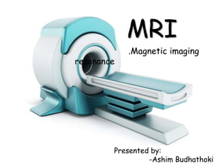
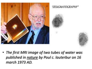
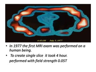
MRI
.Magnetic imaging
resonance
Presented by:
-Ashim Budhathoki
Introduction
• It is radiological imaging technique.
• It is a medical imaging modality which uses non-ionizing
radiation rather than ionizing radiation to produce image of
body structures inside the body.
• It uses magnetic field, pulses, radio waves ,radio frequency
energy and computer system.
• Alternatively MRI machine is also termed as NMR.
• It is bashed on principle of nuclear magnetic resonance
(NMR).
History
• Several scientists involved.
1-Raymond Damadian- 1971
-Idea very sketchy, no images produces.
2-paul c. Lauterbur- 1973
-For the first time he creates MR image.
-Image technique for 2D and 3D imaging.
3-peter Mansfield
-develop a mathematical technique where scan
takes seconds rather the producing clearer image.
• The first MRI image of two tubes of water was
published in nature by Poul c. lauterbur on 16
march 1973 AD.
“ZEUGMATOGRAPHY”
• In 1977 the first MRI exam was performed on a
human being.
• To create single slice it took 4 hour.
performed with field strength 0.05T
Nobel prize-2003
-Paul c. lauterbur and peter Mansfield are awarded in
physiology or medicine of their discoveries of MRI.
OLDER MRI MACHINES
Components
Magnet
Gradient
coil
Shim coil RF coil Computer
Magnet (static magnetic field coil)
• It works under the principle of electromagnetism:
-”whenever an electric current passes through a conductor, a magnetic
field is created in the region around the conductor.”
 It consists of many coils of
wire through which electricity
passes resulting in a huse magnetic field.
- The magnet currently used in scanner today are
in (0.5-2.0) tesla range (5000-20000)gauss.
.<1 tesla-1000 gauss>
- While earth magnetic field is 0.5 gauss.
Gradient coil
• There are 3 gradient coils within the main magnet ie. X,Y,Z
gradient coil which produce 3 different magnetic fields each
are less strong than main magnet .
• They has capacity to image directionally along X,Y,Z axis by
changing precessional frequencies.
---And shim coil adjust the magnetic field to make it more uniform.
Axial image
Saggital image
Coronal image
RF coil
• RF coil act as transmitter and receiver.
• They are used as the Z gradient coil in MRI scanner.
• That transmit the RF signal and receives the return
signal.
Did you know?
The force of the magnetic field
from an MRI machine is so strong that it
will cause a loaded gun to spontaneously
discharge even with the safety on.
--The force of the magnetic field from an MRI machine is so strong that
it will cause a loaded gun to spontaneously discharge even with the safety on.
Difference between CT and MRI
MRI
 Granty of MRI consists of
small hole than CT scan.
 magnetic signals are used
 Good for visualization of
soft tissue
 High spatial resolution
 Typically takes 30-40
minutes
CT
 Granty of CT consists of
bigger hole than MRI scan.
 Ionizing radiation are used
 Good for visualization of
organs and bony detail
 Long distance resolution
 Generally within 5 minutes
Disadvantages
• Claustrophobic patient are contraindicated.
• Patient with metallic implanted and and pacemaker are
contraindicated.
• Had surgery in the last 2 week patient are contraindicated.
• RF transmitters can cause severe burn if it is misused or
mishandled.
• Relatively expensive.
• Lengthy procedure.
eg, To perform a pituitary gland can take up to 30 minutes.
Why pregnant women can’t
perform MRI scan ??
- If contrast is injected
-if injected contrast dye got into the
placenta there is risk of miscarriage.
- MRI tissue hiting
-RF pulse can do potentially harm to
tissue of part of examination.
- if it is necessary scan can be performed
after 3 month of pregnancy.
- If contrast is injected
-if injected contrast dye got into the
placenta there is risk of miscarriage.
(NOTE: MRI tissue hitting RF pulse can do potentially
harm to tissue of part of examination, if it is
necessary scan can be performed
after 3 month of pregnancy.
Super conductor
• Ideally, no magnet has 100% conductivity .It consists of some resistance.
• If we place any conductor in extreme low temperature then, its resistance
will be almost zero and starts acting as a super conductor.
• The critical temperature required to produce zero resistance for alloy is
-269ᵒc and this can be achieved by immersing the coil in a bath of liquid
helium.
Principle of MrI
• MRI forms image with reference to the hydrogen atom present with
in the human body.
• The principle of formation MRI imaging can be described as follows.
-Net magnetization
-precession
-Resonance
-Transverse magnetization
-Longitudinal magnetization
-image formation
• The principle of MRI is bashed on basic principle of NMR.
NMR (nuclear magnetic resonance)
• The theory behind NMR comes from the spin of a nucleus and it generates
a magnetic field.
• Without a external applied magnetic field, the nuclear spin are in random
in direction.
• But when external magnetic field is applied nuclei align themselves to or
against the direction of external magnet.
Why protons are important
to MRI?
• Positively (+ve) charged .
• Spin about a central axis.
• During spinning the charge
creates a magnetic field around it.
• The straight arrow (vector) indicates
the direction of the magnetic field.
Manyotherelementsofourbodyfulfillsthecriteria ofMR
imagingbut,
why we takehydrogenatomasreference?
• Our body composed of more than 83% of water.
>1 hydrogen atom consists of 2 hydrogen atom
• Each hydrogen atom consists of single proton which spins around
the nucleus resulting production of magnetic field.
• Thus each hydrogen atom acts as a tiny magnet.
Why I am a not
magnet?• In the absence of applied magnetic field those
hydrogen atom are randomly oriented in our
body cancelling to each other by giving out net
magnetization zero.
Net magnatization=0
Net magnetization
• When we place our body near to the huse magnetic
field the randomly oriented those tiny magnet align
to the direction of huse magnetic field.
precession
• Due to influence of external magnetic field those tiny magnet
shows spinning as well as wobbling movement around the
nucleus on its own axis. Those two movements combine called
as a precession or lamor precession.
• Each hydrogen atom precise on the particular frequency
called as a Precessional frequency, which can be ruled out by :
LAMOR EQUATION.
−𝛾 𝑟𝑎𝑡𝑖𝑜 𝑜𝑓 ℎ𝑦𝑑𝑟𝑜𝑔𝑒𝑛 𝑖𝑠 42.57
𝑀𝐻𝑍
𝑇
• Hydrogen has different precessional frequency at different field strength. For
example,
at 1.5T – 63.86 MHZ (42.57 MHZ × 1.5T)
at 1.0T - 42.57 MHZ (42.57 MHZ× 1.0T)
at 0.5T - 42.57 MHZ (42.57 MHZ× 0.5T)
.
Resonance
• If we add external energy ie RF pulse to those aligned
hydrogen atom where the frequency is equal or close to
precessional frequency of hydrogen proton , then the energy
get summed up, this phenomenon is called resonance.
 Result of resonance:
-Due to resonance those précising hydrogen atom move
away from the alignment of huse magnetic field ie. B₀.
--The angle to which the tiny magnet
moves out of alignment is called
flip angle.
FLIP ANGLE
• -The angle to which the NMV moves out of alignment is called
flip angle.
• The magnitude of flip angle depends upon the amplitude and
duration of the RF pulse applied.
• Normally flip angle is 90° ,although FA can be chosen between
(1° to 180°).
Transverse magnetization
• When RF pulse is applied ie. excitation, those longitudinally
aligned hydrogen atom magnetic direction moves to
transverse direction ,such alignment is known as a transverse
magnetization.
Longitudinal magnetization
• When RF pulse is stopped the resonance stops, then relaxation
occurs, and the energy of tiny magnet cannot overcome the
energy of external magnetic field resulting alignment in
longitudinal direction, this alignment is called longitudinal
magnetization.
TR ( repetition time)
• The time between two excitation pulses is called repetition time.
• Increasing the TR result in following effects:
- less image contrast.
-more PD ( proton density) contrast.
-more signal
-there is more magnetization available for
the next excitation.
-increase of scan time.
TE ( time of echo)
• TE (echo time) : It is the time between the excitation pulse and the
echo.
• Increasing the TE results in following effects
-more T2 contrast
-less signal
• By varying the TR and TE one can abtain T1W and T2W image.
T1 relaxation time
• The time taken by tiny magnet or H2 proton to alignment from
transverse to longitudinal direction is T1 relaxation time.
T1 relaxation in fat and water
• T1 relaxation occurs due to nuclei giving up their
energy to surrounding environment.
• So, slow molecule has rapid relaxation process than
in higher molecule.
• So, T1 recovery time of fat is shorter than water.
• Such image is called T1 weighted image.
T2 decay time
• The time taken by proton to loose the energy in
transverse direction is known as T2 decay time.
• T2 decay time is also different in different matter.
• such images are called T2 weighted image.
T2 decay in fat and water
• T2 decay occurs by exchanging their energy to their neighbors.
It depends on efficient energy exchange in hydrogen atom.
• So, energy exchange is more efficient in fat than in water.
• So T2 decay time of fat is shorter than water.
T1 and T2 weighted image
• T1 weighted image
-water contained eg.CSF –
dark and fat-white.
- white matter brighter than
grey matter.
• T2 weighted image
- water contained
eg. CSF- bright and
fat-dark.
- Grey matter brighter
than white matter.
FID (free induction decay signal)
• Faradays law of induction states that “if the receiver coil is
placed in the area of moving magnetic field then a voltage is
induced in this receiver coil”
• As the magnitude of transverse magnetization decreases , so
does the magnitude of the voltage induced in the receiver coil.
• The induction signal is referred as free induction decay signal.
Image formation
• Imaging
- when the RF pulse is turned off the hydrogen proton slowly return
to their natural alignment with in a magnetic field and release their
excess stored energy. This is known as relaxation.
• What happens to released energy?
1- release as heat.
OR
2-exchanged and absorbed by other proton.
OR
3-released as radio wave.
Image formation
• Measuring the MR signal:
-the moving proton induces a signal in the RF antenna.
-the signal is picked up by a coil and sent to computer system.
-
• The computer receives mathematical data , which is
converted through the use of a fourier transform into an
MR 3D image.
MATRIX
• Amount of anatomy covered of a patient is called field of view
(FOV).
• FOV is square or rectangle shaped and divided into – matrix (picture
element).
• Matrix size is annotated by two figure.
eg. (256*192) matix
No. of frequency sample taken –and – No. of phase encoding performed.
Pixel
• Each square of image matrix is called pixel
( volume + element) and it is represented by block of
tissue called voxel ( volume element).
• pixels don’t have a fixed size , their diameter are
generally measured in micrometer ( microns).
MR effects and safety
• The statement ‘ MRI is totally safe imaging mortality". If
certain well thoughts guidance are followed.
• The MR safety and effects consideration is described as
follows:
1. static magnetic field.
-Biological effects.
- Attraction effects.
1) Radiofrequency effects.
Biological effects
• It states that “the exposure of human to static
magnetic field below 2.5 T is unlikely to have
any adverse effects on health.
• There is no evidence indicating biological side
effects from magnetic field till now , as
research is continuing in this area.
Attraction effects
• A field of 0.5 millitesla (0.5 Mt , 5 gauss) is recognized to be safe from the risk of any
attraction effects.
• Safety measure
-patient and staff must be screened for any ferromagnetic substance eg. Metallic
implants ,pace maker, etc before crossing the 0.5 Mt line.
Radiofrequency effects
• During excitation the energy is absorbed by protons and dissipated as
heat.
• The RF being oscillating electric and magnetic field, induces electric current
within tissue of the patient.
• The RF is transformed into heat within these and it is thermal biological
effects.
• Preventative measure:
-Room temperature =36°c
-maximum body temperature rise should be less
than 1°c.
-localized heating should be no greater than
- 38°c in head.
- 39°c in trunk.
- 40°c in the extremities.
-END-
REFRENCE
 Google
 YouTube
 MRI in practice
 Radiology book of satish k. bhargava

MRI - magnetic Imaging resonance

  • 1.
  • 2.
    Introduction • It isradiological imaging technique. • It is a medical imaging modality which uses non-ionizing radiation rather than ionizing radiation to produce image of body structures inside the body. • It uses magnetic field, pulses, radio waves ,radio frequency energy and computer system. • Alternatively MRI machine is also termed as NMR. • It is bashed on principle of nuclear magnetic resonance (NMR).
  • 3.
    History • Several scientistsinvolved. 1-Raymond Damadian- 1971 -Idea very sketchy, no images produces. 2-paul c. Lauterbur- 1973 -For the first time he creates MR image. -Image technique for 2D and 3D imaging. 3-peter Mansfield -develop a mathematical technique where scan takes seconds rather the producing clearer image.
  • 4.
    • The firstMRI image of two tubes of water was published in nature by Poul c. lauterbur on 16 march 1973 AD. “ZEUGMATOGRAPHY”
  • 5.
    • In 1977the first MRI exam was performed on a human being. • To create single slice it took 4 hour. performed with field strength 0.05T
  • 6.
    Nobel prize-2003 -Paul c.lauterbur and peter Mansfield are awarded in physiology or medicine of their discoveries of MRI.
  • 7.
  • 8.
  • 9.
    Magnet (static magneticfield coil) • It works under the principle of electromagnetism: -”whenever an electric current passes through a conductor, a magnetic field is created in the region around the conductor.”  It consists of many coils of wire through which electricity passes resulting in a huse magnetic field.
  • 10.
    - The magnetcurrently used in scanner today are in (0.5-2.0) tesla range (5000-20000)gauss. .<1 tesla-1000 gauss> - While earth magnetic field is 0.5 gauss.
  • 11.
    Gradient coil • Thereare 3 gradient coils within the main magnet ie. X,Y,Z gradient coil which produce 3 different magnetic fields each are less strong than main magnet . • They has capacity to image directionally along X,Y,Z axis by changing precessional frequencies.
  • 12.
    ---And shim coiladjust the magnetic field to make it more uniform. Axial image Saggital image Coronal image
  • 13.
    RF coil • RFcoil act as transmitter and receiver. • They are used as the Z gradient coil in MRI scanner. • That transmit the RF signal and receives the return signal.
  • 14.
    Did you know? Theforce of the magnetic field from an MRI machine is so strong that it will cause a loaded gun to spontaneously discharge even with the safety on. --The force of the magnetic field from an MRI machine is so strong that it will cause a loaded gun to spontaneously discharge even with the safety on.
  • 15.
    Difference between CTand MRI MRI  Granty of MRI consists of small hole than CT scan.  magnetic signals are used  Good for visualization of soft tissue  High spatial resolution  Typically takes 30-40 minutes CT  Granty of CT consists of bigger hole than MRI scan.  Ionizing radiation are used  Good for visualization of organs and bony detail  Long distance resolution  Generally within 5 minutes
  • 17.
    Disadvantages • Claustrophobic patientare contraindicated. • Patient with metallic implanted and and pacemaker are contraindicated. • Had surgery in the last 2 week patient are contraindicated. • RF transmitters can cause severe burn if it is misused or mishandled. • Relatively expensive. • Lengthy procedure. eg, To perform a pituitary gland can take up to 30 minutes.
  • 18.
    Why pregnant womencan’t perform MRI scan ?? - If contrast is injected -if injected contrast dye got into the placenta there is risk of miscarriage. - MRI tissue hiting -RF pulse can do potentially harm to tissue of part of examination. - if it is necessary scan can be performed after 3 month of pregnancy. - If contrast is injected -if injected contrast dye got into the placenta there is risk of miscarriage. (NOTE: MRI tissue hitting RF pulse can do potentially harm to tissue of part of examination, if it is necessary scan can be performed after 3 month of pregnancy.
  • 19.
    Super conductor • Ideally,no magnet has 100% conductivity .It consists of some resistance. • If we place any conductor in extreme low temperature then, its resistance will be almost zero and starts acting as a super conductor. • The critical temperature required to produce zero resistance for alloy is -269ᵒc and this can be achieved by immersing the coil in a bath of liquid helium.
  • 20.
    Principle of MrI •MRI forms image with reference to the hydrogen atom present with in the human body. • The principle of formation MRI imaging can be described as follows. -Net magnetization -precession -Resonance -Transverse magnetization -Longitudinal magnetization -image formation • The principle of MRI is bashed on basic principle of NMR.
  • 21.
    NMR (nuclear magneticresonance) • The theory behind NMR comes from the spin of a nucleus and it generates a magnetic field. • Without a external applied magnetic field, the nuclear spin are in random in direction. • But when external magnetic field is applied nuclei align themselves to or against the direction of external magnet.
  • 22.
    Why protons areimportant to MRI? • Positively (+ve) charged . • Spin about a central axis. • During spinning the charge creates a magnetic field around it. • The straight arrow (vector) indicates the direction of the magnetic field.
  • 23.
    Manyotherelementsofourbodyfulfillsthecriteria ofMR imagingbut, why wetakehydrogenatomasreference? • Our body composed of more than 83% of water. >1 hydrogen atom consists of 2 hydrogen atom • Each hydrogen atom consists of single proton which spins around the nucleus resulting production of magnetic field. • Thus each hydrogen atom acts as a tiny magnet.
  • 24.
    Why I ama not magnet?• In the absence of applied magnetic field those hydrogen atom are randomly oriented in our body cancelling to each other by giving out net magnetization zero. Net magnatization=0
  • 25.
    Net magnetization • Whenwe place our body near to the huse magnetic field the randomly oriented those tiny magnet align to the direction of huse magnetic field.
  • 26.
    precession • Due toinfluence of external magnetic field those tiny magnet shows spinning as well as wobbling movement around the nucleus on its own axis. Those two movements combine called as a precession or lamor precession.
  • 27.
    • Each hydrogenatom precise on the particular frequency called as a Precessional frequency, which can be ruled out by : LAMOR EQUATION. −𝛾 𝑟𝑎𝑡𝑖𝑜 𝑜𝑓 ℎ𝑦𝑑𝑟𝑜𝑔𝑒𝑛 𝑖𝑠 42.57 𝑀𝐻𝑍 𝑇 • Hydrogen has different precessional frequency at different field strength. For example, at 1.5T – 63.86 MHZ (42.57 MHZ × 1.5T) at 1.0T - 42.57 MHZ (42.57 MHZ× 1.0T) at 0.5T - 42.57 MHZ (42.57 MHZ× 0.5T) .
  • 28.
    Resonance • If weadd external energy ie RF pulse to those aligned hydrogen atom where the frequency is equal or close to precessional frequency of hydrogen proton , then the energy get summed up, this phenomenon is called resonance.  Result of resonance: -Due to resonance those précising hydrogen atom move away from the alignment of huse magnetic field ie. B₀. --The angle to which the tiny magnet moves out of alignment is called flip angle.
  • 29.
    FLIP ANGLE • -Theangle to which the NMV moves out of alignment is called flip angle. • The magnitude of flip angle depends upon the amplitude and duration of the RF pulse applied. • Normally flip angle is 90° ,although FA can be chosen between (1° to 180°).
  • 30.
    Transverse magnetization • WhenRF pulse is applied ie. excitation, those longitudinally aligned hydrogen atom magnetic direction moves to transverse direction ,such alignment is known as a transverse magnetization.
  • 31.
    Longitudinal magnetization • WhenRF pulse is stopped the resonance stops, then relaxation occurs, and the energy of tiny magnet cannot overcome the energy of external magnetic field resulting alignment in longitudinal direction, this alignment is called longitudinal magnetization.
  • 32.
    TR ( repetitiontime) • The time between two excitation pulses is called repetition time. • Increasing the TR result in following effects: - less image contrast. -more PD ( proton density) contrast. -more signal -there is more magnetization available for the next excitation. -increase of scan time.
  • 33.
    TE ( timeof echo) • TE (echo time) : It is the time between the excitation pulse and the echo. • Increasing the TE results in following effects -more T2 contrast -less signal • By varying the TR and TE one can abtain T1W and T2W image.
  • 34.
    T1 relaxation time •The time taken by tiny magnet or H2 proton to alignment from transverse to longitudinal direction is T1 relaxation time.
  • 35.
    T1 relaxation infat and water • T1 relaxation occurs due to nuclei giving up their energy to surrounding environment. • So, slow molecule has rapid relaxation process than in higher molecule. • So, T1 recovery time of fat is shorter than water. • Such image is called T1 weighted image.
  • 36.
    T2 decay time •The time taken by proton to loose the energy in transverse direction is known as T2 decay time. • T2 decay time is also different in different matter. • such images are called T2 weighted image.
  • 37.
    T2 decay infat and water • T2 decay occurs by exchanging their energy to their neighbors. It depends on efficient energy exchange in hydrogen atom. • So, energy exchange is more efficient in fat than in water. • So T2 decay time of fat is shorter than water.
  • 38.
    T1 and T2weighted image • T1 weighted image -water contained eg.CSF – dark and fat-white. - white matter brighter than grey matter. • T2 weighted image - water contained eg. CSF- bright and fat-dark. - Grey matter brighter than white matter.
  • 39.
    FID (free inductiondecay signal) • Faradays law of induction states that “if the receiver coil is placed in the area of moving magnetic field then a voltage is induced in this receiver coil” • As the magnitude of transverse magnetization decreases , so does the magnitude of the voltage induced in the receiver coil. • The induction signal is referred as free induction decay signal.
  • 40.
    Image formation • Imaging -when the RF pulse is turned off the hydrogen proton slowly return to their natural alignment with in a magnetic field and release their excess stored energy. This is known as relaxation. • What happens to released energy? 1- release as heat. OR 2-exchanged and absorbed by other proton. OR 3-released as radio wave.
  • 41.
    Image formation • Measuringthe MR signal: -the moving proton induces a signal in the RF antenna. -the signal is picked up by a coil and sent to computer system. - • The computer receives mathematical data , which is converted through the use of a fourier transform into an MR 3D image.
  • 42.
    MATRIX • Amount ofanatomy covered of a patient is called field of view (FOV). • FOV is square or rectangle shaped and divided into – matrix (picture element). • Matrix size is annotated by two figure. eg. (256*192) matix No. of frequency sample taken –and – No. of phase encoding performed.
  • 43.
    Pixel • Each squareof image matrix is called pixel ( volume + element) and it is represented by block of tissue called voxel ( volume element). • pixels don’t have a fixed size , their diameter are generally measured in micrometer ( microns).
  • 44.
    MR effects andsafety • The statement ‘ MRI is totally safe imaging mortality". If certain well thoughts guidance are followed. • The MR safety and effects consideration is described as follows: 1. static magnetic field. -Biological effects. - Attraction effects. 1) Radiofrequency effects.
  • 45.
    Biological effects • Itstates that “the exposure of human to static magnetic field below 2.5 T is unlikely to have any adverse effects on health. • There is no evidence indicating biological side effects from magnetic field till now , as research is continuing in this area.
  • 46.
    Attraction effects • Afield of 0.5 millitesla (0.5 Mt , 5 gauss) is recognized to be safe from the risk of any attraction effects. • Safety measure -patient and staff must be screened for any ferromagnetic substance eg. Metallic implants ,pace maker, etc before crossing the 0.5 Mt line.
  • 47.
    Radiofrequency effects • Duringexcitation the energy is absorbed by protons and dissipated as heat. • The RF being oscillating electric and magnetic field, induces electric current within tissue of the patient. • The RF is transformed into heat within these and it is thermal biological effects. • Preventative measure: -Room temperature =36°c -maximum body temperature rise should be less than 1°c. -localized heating should be no greater than - 38°c in head. - 39°c in trunk. - 40°c in the extremities.
  • 48.
    -END- REFRENCE  Google  YouTube MRI in practice  Radiology book of satish k. bhargava