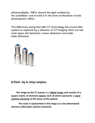
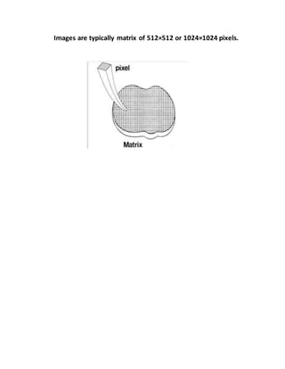
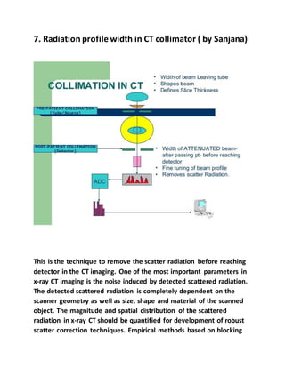
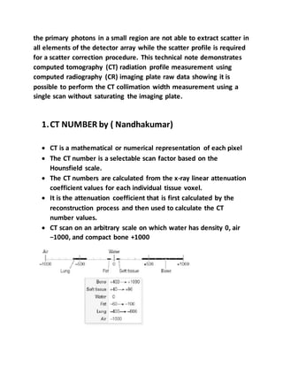
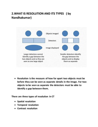
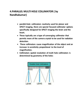
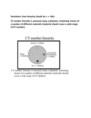
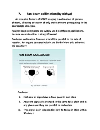
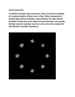
SlideShare a Scribd company logo
CT SCAN - QUESTION AND ANSWER 3 MARKS
Name of the student
Iniya sanjana.A
Nandha kumar.A
Nithya.M
Mano.L
Melhin Hebi.J
Simon.I
Bharath.v
1.Ring artifact: by Iniya sanjana
 Ring artefacts are a CT phenomenon that occurs due to mis
calibration or failure of one or more detector elements in a CT
scanner.
 Less often, it can be caused by insufficient radiation dose or
contrast material contamination of the detector cover.
 They occur close to the iso centre of the scan and are usually
visible on multiple slices at the same location.
 They are a common problem in cranial CT.
2.HRCT ct thorax (by,sanjana)
High-resolution computed tomography (HRCT) is a type of
computed tomography (CT) with specific techniques to
enhance image resolution. It is used in the diagnosis of
various health problems, though most commonly
for lung disease, by assessing the lung parenchyma.
H.R.C.T Technique
HRCT should be done in axial mode.
Selected slice thickness should be .5 to 1.5mm (thin cuts)
Slice gap should be 3 to 5 mm.
Scan field can be limited to include region of interest.
PNS, ORBITS, TEMPORAL BONE are regions meant for
HRCT.
Recent advance machine taking 5mm cuts in axial mode and
breaking into .625 mm cuts by using multi detector and
software.
3.Imagereconstruction (by,iniya sanjana)
Image reconstruction in CT is a mathematical process that
generates tomographic images from multiple X-ray
projection data acquired at many different angles around the
patient. Two major categories of reconstruction methods
exist, analytical reconstruction and iterative reconstruction.
Reconstruction algorithms
There are various algorithms used in CT image
reconstruction, the following are some of the more common
algorithms utilised in commercially available CT today.
 iterative algorithm without statistical modelling
o used originally by Godfrey Hounsfield, however not
commercially used due to the inherent limitations of
microprocessors at that time
o will use an assumption and will compare to the
assumption with its measured data. Then will continue to
make iterations until the two data sets are in agreement.
 iterative algorithm with statistical modelling
o iterative reconstruction with statistical modelling that
takes into account
 optics (x-ray source, image voxels and detector)
 noise (photon statistics)
 physics (data acquisition)
 object (radiation attenuation)
 back projection
o not used in the clinical setting, as it is unable to produce
sharp images
o known for its distinctive artefact that resembles a star
 filtered back projection (convolution method)
o still widely used in CT today
4.CT Number(by,injya sanjana)
(Computed tomography number) The CT number is a
selectable scan factor based on the Hounsfield scale. Each
elemental region of the CTimage (pixel) is expressed in terms
of Hounsfield units (HU) corresponding to the x-ray
attenuation (or tissue density).
5. Scintillation detector (by,iniya sanjana)
A scintillation detector or scintillation counter is obtained
when a scintillator is coupled to an electronic light sensor
such as a photomultiplier tube (PMT), photodiode, or silicon
photomultiplier. PMTs absorb the light emitted by
the scintillator and re-emit it in the form of electrons via the
photoelectric effect.
The difference being that with CT technology the screen-film
system is replaced by a detector. In CT imaging there are two
main types old detectors: xenon detectors and solid-
state detectors
6.Pixel : by A. Iniya sanjana
The image by the CT scanner is a digital image and consists of a
square matrix of elements (pixel), each of which represents a voxel
(volume element) of the tissue of the patient.
The voxel is represented in the image as a two dimensional
element called pixel ( picture element).
Images are typically matrix of 512×512 or 1024×1024 pixels.
7. Radiation profile width in CT collimator ( by Sanjana)
This is the technique to remove the scatter radiation before reaching
detector in the CT imaging. One of the most important parameters in
x-ray CT imaging is the noise induced by detected scattered radiation.
The detected scattered radiation is completely dependent on the
scanner geometry as well as size, shape and material of the scanned
object. The magnitude and spatial distribution of the scattered
radiation in x-ray CT should be quantified for development of robust
scatter correction techniques. Empirical methods based on blocking
the primary photons in a small region are not able to extract scatter in
all elements of the detector array while the scatter profile is required
for a scatter correction procedure. This technical note demonstrates
computed tomography (CT) radiation profile measurement using
computed radiography (CR) imaging plate raw data showing it is
possible to perform the CT collimation width measurement using a
single scan without saturating the imaging plate.
1.CT NUMBER by ( Nandhakumar)
 CT is a mathematical or numerical representation of each pixel
 The CT number is a selectable scan factor based on the
Hounsfield scale.
 The CT numbers are calculated from the x-ray linear attenuation
coefficient values for each individual tissue voxel.
 It is the attenuation coefficient that is first calculated by the
reconstruction process and then used to calculate the CT
number values.
 CT scan on an arbitrary scale on which water has density 0, air
−1000, and compact bone +1000
2.WHAT IS RESOLUTION AND ITS TYPES ( by
Nandhakumar)
 Resolution is the measure of how far apart two objects must be
before they can be seen as separate details in the image. For two
objects to be seen as separate the detectors must be able to
identify a gap between them.
There are three types of resolution in CT
 Spatial resolution
 Temporal resolution
 Contrast resolution
Spatial resolution :
Spatial resolution in CT is the ability to distinguish between
object or structures that differ in density. A high spatial
resolution is important for one to discriminate between
structures that are located within a small proximity to each
other.
Temporal resolution :
The concept of temporal resolution is fundamental to cardiac CT
and MRI, in which a rapidly beating heart is imaged over the
order of milliseconds into multiple frame-captures.
Contrast resolution:
Contrast resolution in radiology refers to the ability of any
imaging modality to distinguish between differences in image
intensity. The inherent contrast resolution of a digital image is
given by the number of possible pixel values, and is defined as
the number of bits per pixel value.
2.MASS ATTENUATION COEFFICIENT ( by
Nandhakumar)
The mass attenuation coefficient is a measurement of how strongly
a chemical species or substance absorbs or scatters light at a given
wavelength, per unit mass.
or
The mass attenuation coefficient is a measure of the probability of
the interaction that occurs between incident photons and the
matter of the unit mass per unit area.
 Mass attenuation coefficient is the ratio between the linear
attenuation coefficient and density.
 The SI unit of mass attenuation coefficient is the square metre
per kilogram (m2/kg). Other common unit cm2/g (the most
common unit for X-ray mass attenuation coefficients)
4.PARALLEL MULTI HOLE COLLIMATOR ( by
Nandhakumar)
 parallel-hole collimators routinely used for planar and
SPECT imaging, there are special focused collimator options
specifically designed for SPECT imaging the brain and the
heart.
 These typically are a type of converging collimator that
permits more of the camera crystal to be used for radiation
detection.
 These collimators cause magnification of the object and an
increase in sensitivity proportional to the level of
magnification.
 Collimators spatial resolution of multi hole collimators is
determined by geometry of the holes
5. WHAT IS LOW DOSE CT SCAN ( by Nandhakumar)
 A CT Scan system that limits the radiation exposure to the
patient and produces high-resolution three-dimensional images
or pictures of the inside of the body.
 Low-dose CT or LDCT uses less ionizing radiation than a
conventional CT scan. In children and young adults, exposure to
CT radiation is of particular concern.
 Low-dose CT is recommended Low-dose Abdominal CT Protocols
With a Tube Voltage Setting of 100 kVp or 80 kVp: Performance
of Radiation Dose Reduction and Influence on Visual Contrast
 low-dose CT scan that is recommended for lung cancer and the
kidney , ureters, and bladder (CT KUB) is the investigation of
choice for renal colic screening is a newer form of CT scan
known as a low-dose spiral or helical CT scan.
For abdominal CT in young adults with suspected appendicitis and
renal calculi.
For pediatric head CT.
For CT screening of Lung and follow up cases.
ADVANTAGES :
 A low-dose CT scan is a quick, less than a minute.
 This type of CT scan uses no dyes, no injections, and requires
nothing to swallow by mouth.
6. What is a CT guided biopsy of organ (by
Nandhakumar)
 A CT-guided biopsy is a procedure by which the radiologist uses
a very thin needle and a syringe to withdraw a tissue or fluid
specimen from an organ or suspected tumour mass for
pathological evaluation.
 The needle is guided while being viewed by the radiologist on a
computed tomography (CT) scan on console.
 CT-guided biopsy can be performed on almost all organs of the
body, for example on the lungs, liver, kidneys, adrenal glands,
pancreas, and pelvis.
7.CT ARTEFACTS ( by Nandhakumar)
 An artefact is a structure or an appearance that is not normally
present on the radiograph or in CT images and is produced by
artificial means.
 CT artefacts are common and can occur for various reasons.
Artefacts are items, are any things made by or used by humans.
 Some examples would be whole pottery, metals, and stone
tools.
There are many different types of CT artefacts,
 Beam hardening artefact
 Scatter artefacts
 motion artefacts
 cone beam artefacts
 Spiral Pitch artefacts
 Partial volume artefacts
 Ring, and metal artefacts.
1.Tomography by nithya
Tomography is a radiological technique for obtaining clear x-
ray images of deep internal structure by focusing on a specific
plane within the body.
It refers to slice view or sectional imaging and is usually
referred as body section radiography
There are two types of tomography, namely
 Linear tomography
 Computed tomography
Linear tomography- In Linear tomography, the image of the
overlying and underlying structures can be blurred by moving the x-
ray tube and film during exposure, about an axis through the
structure of interest.
It is an imaging technique that produces sectional view of
the patient in a plane, parallel to the table top.
Computer tomography- Is a special form of tomography in
which a computer is used to make a mathematical reconstruction
of a tomographic plane or slice.
It generates images in trans axial section, the special features
of CT images are
 Images are cross sectional
 Eliminates the superimposition of structures
 Not influenced by the properties of the neighboring region
2.CTDI- computer tomography dose index: by nithya
o CTDI is measured in mGy
 CTDI is always stated for 100mas value.
 CTDI increases with tube voltage and CTDI of body scans lower than
head, due to greater attenuation in the body.
 The typical effective dose in CT scan is 1-2 mSv for head, 6 mSv for
chest and 4 mSv for abdomen.
 CT scanner needs to be tested for CTDI once in 2 years
 As a part of QA program.
 The CTDI of each CT unit is useful to calculate the effective dose, to
patient and workers.
3.Pitch ( by nithya)
Pitch is a term used in helical CT.
It has two terminologies depending on whether single or
multislice CT scanners
Single slice CT:
The term detector pitch is used and is defined as the ratio
between the table distance traveled in one 360 degree gantry
rotation divided by beam collimation/slice thickness.
Pitch = Table movement per rot/ slice thickness.
for example, if the table traveled 5 mm in one rotation and the
beam collimation was 5 mm then pitch equals 5 mm / 5 mm = 1.0.
Choice of pitch affects both image quality and patient dose.
Multislice CT (MSCT) :
Beam pitch is defined as table distance traveled in one 360° gantry
rotation divided by the total thickness of all simultaneously
acquired slice
Pitch= Distance travelledperrot/ slice thicknessX no of slicesacquired.
4.Cone beam CT ( by nithya)
Cone beam CT (CBCT) is a variant type of computed tomography (CT),
and is used particularly in dental and extremity imaging.
In CBCT, a divergent cone-shaped source of radiation is directed
through the target. The attenuated x-rays are detected on the
opposite side by an x-ray detector, which has multiple in the pixels x
and y-axis
Advantages :
Decreased examination time.
Decreased patient movement artifact’
Increased x-ray tube efficiency.
Disadvantages:
Increased scattered radiation.
Potential for cone beam artifact if an inappropriate reconstruction
algorithm is used.
5.CT guided biopsy ( by nithya)
CT guided procedure benefits
 Precise lesion targeting
 Clear image guidance for
 needle placement
 Immediate post procedure
diagnostic information
 Post procedure bleeding
 Pneumothorax
Types of CT guided procedures
 Drainage catheter placement
 Chest
 Abdomen / Pelvis
 Biopsy
 Lung
 Solid Organ
 Lymph nodes
 Bone
 Tumor ablation
 Vertebroplasty
 Embolization
5. CT NUMBER LINEARITY (by nithya)
In computer tomography it concerns the linear relationship
between calculated CT number and the linear attenuation coefficient
of each element of the object.
Deviations from linearity should be < +- 4HU
CT number linearity is assessed using a phantom containing inserts of
a number of different materials (material should cover a wide range
of CT number).
7. Fan-beam collimation(by nithya)
An essential feature of SPECT imaging is collimation of gamma
photons, allowing detection of only those photons propagating in the
appropriate direction.
Parallel beam collimators are widely used in different applications,
because reconstruction is straightforward.
Fan-beam collimators focus on a focal line parallel to the axis of
rotation. For organs centered within the field of view this enhances
the sensitivity.
Fan-beam
i. Each row of septa have a focal point in one plain
ii. Adjacent septa are arranged in the same focal plain and in
any given row they are parallel to each other
iii. This allows each independent row to focus on plain within
3D object
iv. When processed these rows generate individual
tomographic slices
1.DISCRIBE WINDOW WIDTH. ( BY MANO)
The widow width is the measure of the range of ct number
that an image contains.
That is range of CT numbers displayed in the CT image .
A wider window width (2000 HU), THEREFIRE , Will display a
wider range of CT numbers.
2. TEST FOR RESOLUTIONS IN CT.( by mano)
The spatial resolution depends on the reconstruction algorithm,
so it is important that repeat measurements are made under identical
conditions. If the resolution is determined visually from a bar
phantom the display should be adjusted for optimum viewing.
Current CT scanners have a spatial resolution of 0.5–0.625 mm in the
z-axis, and approximately 0.5 mm in the x- to y-axes.
Visual assessment
A method is through visual assessment using a test device consisting
of a repeated pattern of holes, bars or lines. When measuring the
limiting high contrast resolution using a phantom for high contrast
resolution having sets of test objects of equal diameters and spacing,
the high contrast resolution must be 1 mm or less. (For example the
ACR phantom described elsewhere).
3.ADVANTAGES OF PET CT .( by mano)
1. Superior lesion localisation from near-perfect
anatomy/functional registration with fewer motion artefacts.
2. Better distinction between physiological uptake and pathological
uptake.
3. Consolidation of patients imaging studies.
4. Shorter scan time ( average of 30 mints , vs 60 mints with
standard PET ) by using CT for attenuation correction. This acid in
patient comfort and minimises claustrophobia problems.
5. Follow up scan will help us to compare with previous images and
come to conclusion for treatment purpose.
3. EXPLAIN ABOUT DYNAMIC CT STUDIES. ( BY
MANO)
1. In the dynamic scan mode multiple acquisition covering the
same body region are acquired. Explain of these study types
include:
1. Perfusion studies
2. Bolus tracking studies
3. Teat bolus studies
2. Dynamic scans often have large CTDI volume values because
the scanner reports the sum of the CTDI volume value from each
rotation.
5. IMAGE DISPLAY IN CT.( by mano)
1. The reconstructed image is displayed on the monitor. It is a
digital image.
2. It consists of 2D representation of 3D object in the form of
pixels.
3. Window width and window level is more important and it is
applied to get visual effect for desired visuals.
4. CT pixels size is determined by dividing the FOV by matrix
size which is generally 512 ×512.
5. PIXEL SIZE = FOV (mm)/MATRIX SIZE
6.TUBE POTENTIAL USED IN CT. WHAT IS THE
RADIATION DOSE FROM CHEST CT. (by mano)
Tube potential may be defined as the electrical “potential” difference
between anode and cathode of the x-ray tube. Tube potential is
measured in voltage or kilovoltage ranges in CT and commonly
represented as peak kilovoltage or kVp.
The tube potential used in CT are 80kvp, 100kvp, 120kvp and 140kvp.
It will give effects on image quality and radiation dose for CT in
different body regions and clinical indications.
Tube potential is an important scanning parameter for radiation dose
optimization.
Reduction of tube potential results in increased image contrast of
iodine-enhanced CT as well as increased image noise.
Radiation dose for CT Chest
Routine CT Chest 7 msv
Low dose CT Chest 1.5 msv
1.CT number verification.( J. Melhin)
It is most important to determine the spatial uniformity of
CT number in a given media .This test has been conducted using water
phantom and body phantom for measuring the CT number of water
,bone and air .In simulated clinical conditions, Caliberation scan has
been performed with narrowest slice width at all possible kVp
stations. Average CT number in an region of interest (ROI) of
approximately 1 cm square in the center of the phantom and at four
locations at the phantom periphery are obtained .The filed of view of
the CT is completely uniform. Similarly using a circular uniformity (
water) phantom the aspect ratio (horizontal Vs vertical diameter) has
been measured and it has been found that this is incomplete
congruence of the actual value .This testified the caliper accuracy and
reproducibility .
2.CT Gantry…( J. Melhin)
It is the major part the CT scan system. The gantry is a
ring shaped structure; containing X-ray tube, detector, collimators,
filters, data acquisition system (DAS) ,associated electronics such as
gantry angulation motors ,rotational components, including slip ring
systems and the detector array .where we are positioning with help of
the patient with help of control.
The X-ray tube and detector spin rapidly in the gantry.
The gantry can rotate 360° around its axis.
3.Dose reduction in CT.( J. Melhin)
 Pitch –– Increasing the pitch decreases the dose ,increases
the image noise ,increases the effective section thickness
and ,reduces the scanning time .
 Bowtie filters –– Bowtie beam shaping filters attenuate
off–axis rays to minimize dose and reduce X-ray scattering
effects.
 Shielding –– Bismuth shielding has been used to reduce
dose from CT to superficial radiosensitive organs like lens
and thyroid.
 mA modulation –– mA is adapted to body parts not patient
weight. Thinner parts need less radiation.
 Avoid repetition, Explain instructions properly.
 Tube voltage kV–– Decreasing the tube voltage significantly
reduces the dose.
 Scan length –– Scan length is directly related to CT
radiation dose. A shorter scan length means lower dose.
 AEC systems have a number of potential advantages
,including better control of patient radiation dose,
avoidance of photon starvation artifacts ,reduced load on
the X-ray tube, and the maintenance of image quality in
spite of different attenuation values on CT scans.
4.Gantry tilt assessmentin CT. ( J. Melhin)
This test is performed to determine accuracy of tilt indicators
and to ensure that specified tilt can be accomplished under clinical
conditions. This test can be performed using a therapy localization
film similar to the procedure described in scan localization light
accuracy test. Exposures are given without tilt and with tilt on either
sides. On processed film the tilt angles between two density lines are
measured and compared with the tilt angle indicated on computer
console and gantry. Tilt accuracy should be within 3° and this can be
repeated for different angulations. According to present AERB +or – 2
° error is allowable.
5.Techniques of CT cisternography.(J. Melhin)
CT cisternography is an imaging technique used to diagnose
CSF rhinorrhea or CSF otorrhea ( CSF leaks) ,as CT allows the
assessment of the bones of the base of skull.
Technique:
 Pre – contrast CT is performed with thin slices.
 3–10 ml of an iodinated non – ionic low– osmolar contrast
agent is installed into the thecal Sac after lumbar puncture.
 The patient is then tilted with foot end evaluation and a CT
scan is performed with thin slices; maneuvers that provoke
an active leak ,such as head hanging or sneezing, are
performed to visualize intermittent or occult leaks.
 Post–contrast images are then compared with the Pre–
contrast image to see where the CSF and the contrast are
leaking out.
6.Volume rendering technique in CT. ( J. Melhin)
 Volume rendering is a type of data visualization technique which
creates a three dimensional representation of data. CT and MRI
data are frequently visualized with volume rendering in addition
to other reconstructions and slices.
 Volume rendering techniques can also be applied to
tomosynthesis data.
Clinical applications :
 It is very useful for CT angiography ,
 Virtual colonoscopy ,
 Virtual bronchoscopy ,
 Bony details.
7.Low pass and high pass filters in CT. ( J. Melhin)
High– pass (sharp) filters:
 Provide definitive borders, and edges.
 Used for high contrast areas, musculoskeletal
(increases image noise).
Low– pass ( soft) filters :
 Do not define borders and edges to the same extent
as high –pass filters.
 Used for low contrast areas such as brain, abdomen,
etc.
1.CT DOSE INDEX : by bharath
* CT dose index (CTDI) (measured in mGy) is a standardised measure
of radiation dose output of a CT scanner which allows the user to
compare radiation output of different CT scanners
* The computed tomography dose index (CTDI) is a commonly used
radiation exposure index in X-ray computed tomography (CT), first
defined in 1981.
* The unit of CTDI is the gray (Gy) and it can be used in conjunction
with patient size to estimate the absorbed dose.
* The CTDI and absorbed dose may differ by more than a factor of two
for small patients such as children.
* In the past CTDI100 (measured over a 100 mm long ionisation
chamber) and CTDIw (weighted average of dose across a single slice)
were used; for helical scanners in current use, the parameter CTDIvol
is the more commonly used index.
2 ARTIFACTS OF CT SCAN: (Bharath)
Beam Hardening:
An x-ray beam is composed of individual photons with a range of
energies. As the beam passes through an object, it becomes “harder,”
that is to say its mean energy increases, because the lower-energy
photons are absorbed more rapidly than the higher-energy photons .
Two types of artifact can result from this effect: so-called cupping
artifacts and the appearance of dark bands or streaks between dense
objects in the image.
Cupping Artifacts.—
X rays passing through the middle portion of a uniform cylindrical
phantom are hardened more than those passing though the edges
because they are passing though more material. As the beam
becomes harder, the rate at which it is attenuated decreases, so the
beam is more intense when it reaches the detectors than would be
expected if it had not been hardened. Therefore, the resultant
attenuation profile differs from the ideal profile that would be
obtained without beam hardening . A profile of the CT numbers across
the phantom displays a characteristic cupped shape.
Streaks and Dark Bands.—
In very heterogeneous cross sections, dark bands or streaks can
appear between two dense objects in an image. They occur because
the portion of the beam that passes through one of the objects at
certain tube positions is hardened less than when it passes through
both objects at other tube positions. This type of artifact can occur
both in bony regions of the body and in scans where a contrast
medium has been used. In the chest scan shown in , the contrast
medium has caused artifacts that might be mistaken for disease in
nearby anatomy.
3.USES OF CT SCAN: (bharath)
* Examine internal and bone injuries from vehicle accidents or other
trauma
* Diagnose spinal problems and skeletal injuries
* Detect osteoporosis
* Detect many different types of cancers and determine the extent
(spread) of the tumors
* Locate infections
* Look for injuries, stroke-causing clots, hemorrhaging, and other
issues in the head
* Image the lungs to reveal blood clots in the lungs' vessels, excess
fluid, pneumonia, and chronic pulmonary obstructive disease (COPD)
* Determine the cause of chest or abdominal pain, difficulty
breathing, and other symptoms
* Diagnose dangerous vascular diseases that can cause stroke, kidney
failure, and death
* Additionally, CT scans are used to assist with biopsies and other
medical procedures, and help with treatment planning for organ
transplants, gastric bypass, and cancer, among other things.
4.CT:COMPUTED TOMOGRAPHY ( bharath)
CT scans, also called CAT scans, use a rotating X-ray machine to create
cross-sectional, or 3D, images of any body part, They provide a
painless, noninvasive and fast way for doctors to examine bones,
organs and other internal tissues.
WORKING OF CT SCAN:
* During a CT scan, the patient lies on a table that moves through a
doughnut-like ring known as a gantry
* The gantry has an X-ray tube that rotates around the patient while
shooting narrow beams of X-rays through the body.
* The X-rays are picked up by digital detectors directly opposite the
source.
* After the X-ray source completes a full rotation, a sophisticated
computer creates a 2D image of that slice of the body, which typically
ranges from 0.04 to 0.4 inches (1 to 10 millimeters) thick.
* The computer then combines several 2D slices to create a 3D image
of the body, making it easier for a doctor to pinpoint where the
patient's problem exists.
* The scan itself typically takes less than 15 minutes depending on the
area of the body being imaged.
* To make it easier to identify abnormalities, the patient may be given
a contrast material. Solutions containing contrast materials, such as
iodine or barium, are introduced into the body orally, rectally or
injected directly into the bloodstream, depending on the target tissue.
* The materials in the solution work by temporarily altering how X-
rays interact with certain body tissues, which makes those tissues
appear different in the resulting image. The contrast helps doctors
distinguish between normal and abnormal tissue.
5 3D CT DEFINITION: ( bharath)
3D Computed Tomography (CT) is a nondestructive scanning
technology that allows you to view and inspect the external and
internal structures of an object in 3D space. Computed Tomography
works by taking hundreds or thousands of 2D Digital Radiography
projections around a 360 degree rotation of an object.
DIFFERENT TYPES OF CT SCAN:( BASED ON GENERATION)
* First Generation: Rotate/Translate, Pencil Beam.
* Second Generation: rotate/Translate, Narrow Fan Beam.
* Third Generation: Rotate/Rotate, Wide Fan Beam.
* Fourth Generation: Rotate/Stationary.
* Fifth Generation: Stationary/Stationary.
* Sixth Generation: Helical.
* Seventh generation: multiple detector.
6.VIEWING WINDOW IN CT SCAN: ( by bharath)
HOUSNFIED UNITS:
* Numeric information in each pixel of the CT image
* Related to composition and nature of tissue
* Represent the density of tissue
* Also called as CT number.
1 BOWTIE FILTER BY SIMON
Bowtie filter is a metallic filter and it is shape like man's tie, that
shape in a bow.
The term “bowtie” applies to a class of filter shapes featuring
bilateral symmetry with a thickness that increases with the distance
from the centre.
Filtering shapes the x-ray beam intensity. Removing low-energy x-rays
minimizes patient exposure and produces a more uniform beam.
Bowtie filters are commonly employed in CT scanners to
minimize radiation dose, by reducing intensity variations across
detector elements in the presence of patient anatomy.
This filtration modifies a number of x‐ray beam properties
(effective energy, flux, first and second order statistics), making
them non‐uniform across the fan beam field of view.
2.Types of image reconstructionby Simon
Reconstruction algorithms
There are various algorithms used in CT image reconstruction, the
following
are some of the more common algorithms utilised in commercially
available CT
today.
• iterative algorithm without statistical modelling
o used originally by Godfrey Hounsfield, however not commercially
used
due to the inherent limitations of microprocessors at that time
o will use an assumption and will compare to the assumption with its
measured data. Then will continue to make iterations until the two
data
sets are in agreement.
• iterative algorithm with statistical modelling
o iterative reconstruction with statistical modelling that takes into
account
▪ optics (x-ray source, image voxels and detector)
▪ noise (photon statistics)
▪ physics (data acquisition)
▪ object (radiation attenuation)
• back projection
o not used in the clinical setting, as it is unable to produce sharp
images
o known for its distinctive artefact that resembles a star
• filtered back projection (convolution method)
o still widely used in CT today
o utilises a convolution filter to alleviate the blurring associated with
back
projection
o fast, however, has several limitations including noise and artefact
creation
3. CT CHOLANGIOGRAPHY: by simon
• CT cholangiography is a technique of imaging
the biliary tree with the usage of hepatobiliary
excreted contrast. It is useful in delineating
biliary anatomy, identifying a bile leak or looking
for retained gallstones within the biliary system.
• A CT Cholangiogram is the injection of ‘Contrast’
(once called X-ray dye) into the bloodstream to
look at the bile ducts. This Contrast is called
Biliscopin®. When Biliscopin® is injected into
your body it is removed by your liver into the
bile.
• Ct cholangiopraphy has been used to describe
two techniques negative and positive contrast
media.
• The negative contrast makes use of bile as a
negative contrast agent to display the bilary tree
by using a various reformating techniques.
• The positive contrast agents are either IV or oral
Contrast agens that are excreted preferentially
by the liver to opacity the bile ducts.
4.SPIRAL/HELICAL CT by simon.I
 With helical CT, the patient is moved through a rotating x-ray
beam and detector set. From the perspective of the patient, the
x-ray beam from the CT traces a helical path. The helical path
results in a three-dimensional data set, which can then be
reconstructed into sequential images for a stack.
 Helical CT allows a scan to be performed in a single breath-hold.
 A technique where by the patient is transported continuously
through the gantry while data are aquired continuously during
several 360 degree scans.
Advantages of spiral/ helical CT
 Increased speed a study
 Less motion artifact
 Exact continuity of images.
5.Principles of CT: by simon
 The basic principle behind CT is that the internal structure of an
object can be reconstructed from multiple projections of the
object.
 The ray projections are formed by scanning a thin cross section
of the body with a narrow x-ray beam and measuring the
transmitted radiation with a sensitive radiation detector.
 CT scanning is a systematic collection and representation of
projection data.
The main parts of the CT system are Gantry, Table and console.
Gantry
Table
Console.
CT SCAN - 3 Marks - QUESTION AND ANSWERS

More Related Content

What's hot

CT artifact
CT artifact CT artifact
CT artifact
Ganesan Yogananthem
 
CT numbers, window width and window level
CT numbers, window width and window levelCT numbers, window width and window level
CT numbers, window width and window level
Ganesan Yogananthem
 
Ct instrumentation and types of detector configuration
Ct instrumentation and types of detector configurationCt instrumentation and types of detector configuration
Ct instrumentation and types of detector configuration
SUJAN KARKI
 
Ct head protocols
Ct head protocolsCt head protocols
Ct head protocols
Maajid Mohi ud din
 
CT Image reconstruction
CT Image reconstructionCT Image reconstruction
CT Image reconstruction
Santosh Ojha
 
Image reconstruction in computed tomography
Image reconstruction in computed tomographyImage reconstruction in computed tomography
Image reconstruction in computed tomography
Manojzz Bhatta
 
Helical and Multislice CT
Helical and Multislice CTHelical and Multislice CT
Helical and Multislice CT
Manojzz Bhatta
 
Spiral helical, mSCT MDCT, Dual source ct, EBCT, CBCT, portable CT.pptx
Spiral helical, mSCT MDCT, Dual source ct, EBCT, CBCT, portable CT.pptxSpiral helical, mSCT MDCT, Dual source ct, EBCT, CBCT, portable CT.pptx
Spiral helical, mSCT MDCT, Dual source ct, EBCT, CBCT, portable CT.pptx
AASIF LONE
 
Multi slice ct ppt
Multi slice ct pptMulti slice ct ppt
Multi slice ct ppt
Anand Rk
 
CT image acquisition
CT image acquisitionCT image acquisition
CT image acquisition
dypradio
 
CT RADIATION DOSE REDUCTION
CT RADIATION DOSE REDUCTION CT RADIATION DOSE REDUCTION
CT RADIATION DOSE REDUCTION
Ganesan Yogananthem
 
Difference Between Single Slice and Multi Slice CT Scanner
Difference Between Single Slice and Multi Slice CT ScannerDifference Between Single Slice and Multi Slice CT Scanner
Difference Between Single Slice and Multi Slice CT Scanner
Abdul Rehman (R)(CT)(MR)
 
Post processing of computed tomography
Post processing of computed tomographyPost processing of computed tomography
Post processing of computed tomography
BeuniquewithNehaSing
 
Image reconstrsuction in ct pdf
Image reconstrsuction in ct pdfImage reconstrsuction in ct pdf
Image reconstrsuction in ct pdf
mitians
 
Principles of ct
Principles of ctPrinciples of ct
Principles of ct
RMLIMS
 
Physics of Multidetector CT Scan
Physics of Multidetector CT ScanPhysics of Multidetector CT Scan
Physics of Multidetector CT Scan
Dr Varun Bansal
 
Basic Pulse Sequences In MRI
Basic Pulse Sequences In MRIBasic Pulse Sequences In MRI
Basic Pulse Sequences In MRI
Upakar Paudel
 
Portable ct mobile ct
Portable ct mobile ctPortable ct mobile ct
Portable ct mobile ct
anilayyakutty
 
MDCT Principles and Applications- Avinesh Shrestha
MDCT Principles and Applications- Avinesh ShresthaMDCT Principles and Applications- Avinesh Shrestha
MDCT Principles and Applications- Avinesh Shrestha
Avinesh Shrestha
 
Ct tube and detectors
Ct tube and detectorsCt tube and detectors
Ct tube and detectors
sandip suman
 

What's hot (20)

CT artifact
CT artifact CT artifact
CT artifact
 
CT numbers, window width and window level
CT numbers, window width and window levelCT numbers, window width and window level
CT numbers, window width and window level
 
Ct instrumentation and types of detector configuration
Ct instrumentation and types of detector configurationCt instrumentation and types of detector configuration
Ct instrumentation and types of detector configuration
 
Ct head protocols
Ct head protocolsCt head protocols
Ct head protocols
 
CT Image reconstruction
CT Image reconstructionCT Image reconstruction
CT Image reconstruction
 
Image reconstruction in computed tomography
Image reconstruction in computed tomographyImage reconstruction in computed tomography
Image reconstruction in computed tomography
 
Helical and Multislice CT
Helical and Multislice CTHelical and Multislice CT
Helical and Multislice CT
 
Spiral helical, mSCT MDCT, Dual source ct, EBCT, CBCT, portable CT.pptx
Spiral helical, mSCT MDCT, Dual source ct, EBCT, CBCT, portable CT.pptxSpiral helical, mSCT MDCT, Dual source ct, EBCT, CBCT, portable CT.pptx
Spiral helical, mSCT MDCT, Dual source ct, EBCT, CBCT, portable CT.pptx
 
Multi slice ct ppt
Multi slice ct pptMulti slice ct ppt
Multi slice ct ppt
 
CT image acquisition
CT image acquisitionCT image acquisition
CT image acquisition
 
CT RADIATION DOSE REDUCTION
CT RADIATION DOSE REDUCTION CT RADIATION DOSE REDUCTION
CT RADIATION DOSE REDUCTION
 
Difference Between Single Slice and Multi Slice CT Scanner
Difference Between Single Slice and Multi Slice CT ScannerDifference Between Single Slice and Multi Slice CT Scanner
Difference Between Single Slice and Multi Slice CT Scanner
 
Post processing of computed tomography
Post processing of computed tomographyPost processing of computed tomography
Post processing of computed tomography
 
Image reconstrsuction in ct pdf
Image reconstrsuction in ct pdfImage reconstrsuction in ct pdf
Image reconstrsuction in ct pdf
 
Principles of ct
Principles of ctPrinciples of ct
Principles of ct
 
Physics of Multidetector CT Scan
Physics of Multidetector CT ScanPhysics of Multidetector CT Scan
Physics of Multidetector CT Scan
 
Basic Pulse Sequences In MRI
Basic Pulse Sequences In MRIBasic Pulse Sequences In MRI
Basic Pulse Sequences In MRI
 
Portable ct mobile ct
Portable ct mobile ctPortable ct mobile ct
Portable ct mobile ct
 
MDCT Principles and Applications- Avinesh Shrestha
MDCT Principles and Applications- Avinesh ShresthaMDCT Principles and Applications- Avinesh Shrestha
MDCT Principles and Applications- Avinesh Shrestha
 
Ct tube and detectors
Ct tube and detectorsCt tube and detectors
Ct tube and detectors
 

Similar to CT SCAN - 3 Marks - QUESTION AND ANSWERS

Comparison of ct and cbct
Comparison of ct and cbct Comparison of ct and cbct
Comparison of ct and cbct
Amritha James
 
Computed tomography
Computed tomographyComputed tomography
Computed tomography
Rituraj Mishra
 
Basic principle of CT and generation of CT.pptx
Basic principle of CT and generation of CT.pptxBasic principle of CT and generation of CT.pptx
Basic principle of CT and generation of CT.pptx
sarita gaire
 
COMPUTED TOMOGRAPHY SCAN
COMPUTED TOMOGRAPHY SCANCOMPUTED TOMOGRAPHY SCAN
COMPUTED TOMOGRAPHY SCANShounak Nandi
 
Computed Tomography and Spiral Computed Tomography
Computed Tomography and Spiral Computed Tomography Computed Tomography and Spiral Computed Tomography
Computed Tomography and Spiral Computed Tomography
JAMES JACKY
 
Ct Basics
Ct BasicsCt Basics
Ct Basics
Pramod Krishnan
 
Sandhya Dhyani (48437) CT SCAN AND MRI.pptx
Sandhya Dhyani (48437) CT SCAN AND MRI.pptxSandhya Dhyani (48437) CT SCAN AND MRI.pptx
Sandhya Dhyani (48437) CT SCAN AND MRI.pptx
GBPUAT Pantnagar
 
Computer Tomography
Computer TomographyComputer Tomography
Computer Tomography
Lovnish Thakur
 
COMPUTED TOMOGRAPHY
COMPUTED TOMOGRAPHY COMPUTED TOMOGRAPHY
COMPUTED TOMOGRAPHY
vamsi krishna
 
computedtomography-170122041110.pdf
computedtomography-170122041110.pdfcomputedtomography-170122041110.pdf
computedtomography-170122041110.pdf
VanshikaGarg76
 
Computed tomography
Computed tomographyComputed tomography
Computed tomography
Rituraj Mishra
 
Computer Tomography (CT Scan)
Computer Tomography (CT Scan)Computer Tomography (CT Scan)
Computer Tomography (CT Scan)
Likan Patra
 
Patient data acquisition and treatment verification.pptx
Patient data acquisition and treatment verification.pptxPatient data acquisition and treatment verification.pptx
Patient data acquisition and treatment verification.pptx
Juliyet K Joy
 
Image Quality And Artifacts in Computed Tomography.pptx
Image Quality And Artifacts in Computed Tomography.pptxImage Quality And Artifacts in Computed Tomography.pptx
Image Quality And Artifacts in Computed Tomography.pptx
ivanKeshari
 
Diagnostic imaging in head and neck pathology
Diagnostic imaging in head and neck pathologyDiagnostic imaging in head and neck pathology
Diagnostic imaging in head and neck pathologyHayat Youssef
 
Computed Tomography
Computed TomographyComputed Tomography
Computed Tomography
Sujan Poudel
 
computed Tomography
computed Tomographycomputed Tomography
3.ppt
3.ppt3.ppt
Computed Tomography
Computed TomographyComputed Tomography

Similar to CT SCAN - 3 Marks - QUESTION AND ANSWERS (20)

Comparison of ct and cbct
Comparison of ct and cbct Comparison of ct and cbct
Comparison of ct and cbct
 
Computed tomography
Computed tomographyComputed tomography
Computed tomography
 
Basic principle of CT and generation of CT.pptx
Basic principle of CT and generation of CT.pptxBasic principle of CT and generation of CT.pptx
Basic principle of CT and generation of CT.pptx
 
COMPUTED TOMOGRAPHY SCAN
COMPUTED TOMOGRAPHY SCANCOMPUTED TOMOGRAPHY SCAN
COMPUTED TOMOGRAPHY SCAN
 
Computed Tomography and Spiral Computed Tomography
Computed Tomography and Spiral Computed Tomography Computed Tomography and Spiral Computed Tomography
Computed Tomography and Spiral Computed Tomography
 
Ct Basics
Ct BasicsCt Basics
Ct Basics
 
Sandhya Dhyani (48437) CT SCAN AND MRI.pptx
Sandhya Dhyani (48437) CT SCAN AND MRI.pptxSandhya Dhyani (48437) CT SCAN AND MRI.pptx
Sandhya Dhyani (48437) CT SCAN AND MRI.pptx
 
Computer Tomography
Computer TomographyComputer Tomography
Computer Tomography
 
COMPUTED TOMOGRAPHY
COMPUTED TOMOGRAPHY COMPUTED TOMOGRAPHY
COMPUTED TOMOGRAPHY
 
computedtomography-170122041110.pdf
computedtomography-170122041110.pdfcomputedtomography-170122041110.pdf
computedtomography-170122041110.pdf
 
Computed tomography
Computed tomographyComputed tomography
Computed tomography
 
CT SCAN
CT SCANCT SCAN
CT SCAN
 
Computer Tomography (CT Scan)
Computer Tomography (CT Scan)Computer Tomography (CT Scan)
Computer Tomography (CT Scan)
 
Patient data acquisition and treatment verification.pptx
Patient data acquisition and treatment verification.pptxPatient data acquisition and treatment verification.pptx
Patient data acquisition and treatment verification.pptx
 
Image Quality And Artifacts in Computed Tomography.pptx
Image Quality And Artifacts in Computed Tomography.pptxImage Quality And Artifacts in Computed Tomography.pptx
Image Quality And Artifacts in Computed Tomography.pptx
 
Diagnostic imaging in head and neck pathology
Diagnostic imaging in head and neck pathologyDiagnostic imaging in head and neck pathology
Diagnostic imaging in head and neck pathology
 
Computed Tomography
Computed TomographyComputed Tomography
Computed Tomography
 
computed Tomography
computed Tomographycomputed Tomography
computed Tomography
 
3.ppt
3.ppt3.ppt
3.ppt
 
Computed Tomography
Computed TomographyComputed Tomography
Computed Tomography
 

More from Ganesan Yogananthem

nuclear medicine 10 marks questions and answers.docx
nuclear medicine 10 marks questions and answers.docxnuclear medicine 10 marks questions and answers.docx
nuclear medicine 10 marks questions and answers.docx
Ganesan Yogananthem
 
nuclear medicine 3 marks questions and answers.pdf
nuclear medicine 3 marks questions and answers.pdfnuclear medicine 3 marks questions and answers.pdf
nuclear medicine 3 marks questions and answers.pdf
Ganesan Yogananthem
 
MAGNETIC RESONANCE IMAGING QUESTION AND ANSWER 3 MARKS.pdf
MAGNETIC RESONANCE IMAGING QUESTION AND ANSWER 3 MARKS.pdfMAGNETIC RESONANCE IMAGING QUESTION AND ANSWER 3 MARKS.pdf
MAGNETIC RESONANCE IMAGING QUESTION AND ANSWER 3 MARKS.pdf
Ganesan Yogananthem
 
QUESTIONS & ANSWERS FOR QUALITY ASSURANCE, RADIATIONBIOLOGY& RADIATION HAZARD...
QUESTIONS & ANSWERS FOR QUALITY ASSURANCE, RADIATIONBIOLOGY& RADIATION HAZARD...QUESTIONS & ANSWERS FOR QUALITY ASSURANCE, RADIATIONBIOLOGY& RADIATION HAZARD...
QUESTIONS & ANSWERS FOR QUALITY ASSURANCE, RADIATIONBIOLOGY& RADIATION HAZARD...
Ganesan Yogananthem
 
MRI 3-Marks QUESTIONS AND ANSWERS
MRI 3-Marks QUESTIONS AND ANSWERSMRI 3-Marks QUESTIONS AND ANSWERS
MRI 3-Marks QUESTIONS AND ANSWERS
Ganesan Yogananthem
 
Ultrasound assignment 3 mark question and answer
Ultrasound assignment 3 mark question and answer Ultrasound assignment 3 mark question and answer
Ultrasound assignment 3 mark question and answer
Ganesan Yogananthem
 
Radiology procedure questions and answer 1
Radiology procedure questions and answer 1Radiology procedure questions and answer 1
Radiology procedure questions and answer 1
Ganesan Yogananthem
 
Radiological procedure questions and answers2 converted
Radiological procedure questions and answers2 convertedRadiological procedure questions and answers2 converted
Radiological procedure questions and answers2 converted
Ganesan Yogananthem
 
B.Sc RADIOLOGY QUESTION AND ANSWER BANK - POSITIONING
B.Sc RADIOLOGY QUESTION AND ANSWER BANK - POSITIONING B.Sc RADIOLOGY QUESTION AND ANSWER BANK - POSITIONING
B.Sc RADIOLOGY QUESTION AND ANSWER BANK - POSITIONING
Ganesan Yogananthem
 
BIOLOGICAL EFFECTS OF IONIZING RADIATION
BIOLOGICAL EFFECTS OF IONIZING RADIATIONBIOLOGICAL EFFECTS OF IONIZING RADIATION
BIOLOGICAL EFFECTS OF IONIZING RADIATION
Ganesan Yogananthem
 
RADIOGRAPHIC VIEWS FOR HIP JOINT
RADIOGRAPHIC VIEWS FOR HIP JOINTRADIOGRAPHIC VIEWS FOR HIP JOINT
RADIOGRAPHIC VIEWS FOR HIP JOINT
Ganesan Yogananthem
 
RADIOGRAPHIC VIEWS OF ANKLE JOINT
RADIOGRAPHIC VIEWS OF ANKLE JOINTRADIOGRAPHIC VIEWS OF ANKLE JOINT
RADIOGRAPHIC VIEWS OF ANKLE JOINT
Ganesan Yogananthem
 
BASIC MRI SEQUENCES
BASIC MRI SEQUENCESBASIC MRI SEQUENCES
BASIC MRI SEQUENCES
Ganesan Yogananthem
 
Portal venous doppler
Portal venous dopplerPortal venous doppler
Portal venous doppler
Ganesan Yogananthem
 
Radiograpic views for shoulder joint
Radiograpic views  for shoulder jointRadiograpic views  for shoulder joint
Radiograpic views for shoulder joint
Ganesan Yogananthem
 
CSF flow study
CSF flow studyCSF flow study
CSF flow study
Ganesan Yogananthem
 
Digital X-ray Problems..
Digital X-ray Problems..Digital X-ray Problems..
Digital X-ray Problems..
Ganesan Yogananthem
 

More from Ganesan Yogananthem (17)

nuclear medicine 10 marks questions and answers.docx
nuclear medicine 10 marks questions and answers.docxnuclear medicine 10 marks questions and answers.docx
nuclear medicine 10 marks questions and answers.docx
 
nuclear medicine 3 marks questions and answers.pdf
nuclear medicine 3 marks questions and answers.pdfnuclear medicine 3 marks questions and answers.pdf
nuclear medicine 3 marks questions and answers.pdf
 
MAGNETIC RESONANCE IMAGING QUESTION AND ANSWER 3 MARKS.pdf
MAGNETIC RESONANCE IMAGING QUESTION AND ANSWER 3 MARKS.pdfMAGNETIC RESONANCE IMAGING QUESTION AND ANSWER 3 MARKS.pdf
MAGNETIC RESONANCE IMAGING QUESTION AND ANSWER 3 MARKS.pdf
 
QUESTIONS & ANSWERS FOR QUALITY ASSURANCE, RADIATIONBIOLOGY& RADIATION HAZARD...
QUESTIONS & ANSWERS FOR QUALITY ASSURANCE, RADIATIONBIOLOGY& RADIATION HAZARD...QUESTIONS & ANSWERS FOR QUALITY ASSURANCE, RADIATIONBIOLOGY& RADIATION HAZARD...
QUESTIONS & ANSWERS FOR QUALITY ASSURANCE, RADIATIONBIOLOGY& RADIATION HAZARD...
 
MRI 3-Marks QUESTIONS AND ANSWERS
MRI 3-Marks QUESTIONS AND ANSWERSMRI 3-Marks QUESTIONS AND ANSWERS
MRI 3-Marks QUESTIONS AND ANSWERS
 
Ultrasound assignment 3 mark question and answer
Ultrasound assignment 3 mark question and answer Ultrasound assignment 3 mark question and answer
Ultrasound assignment 3 mark question and answer
 
Radiology procedure questions and answer 1
Radiology procedure questions and answer 1Radiology procedure questions and answer 1
Radiology procedure questions and answer 1
 
Radiological procedure questions and answers2 converted
Radiological procedure questions and answers2 convertedRadiological procedure questions and answers2 converted
Radiological procedure questions and answers2 converted
 
B.Sc RADIOLOGY QUESTION AND ANSWER BANK - POSITIONING
B.Sc RADIOLOGY QUESTION AND ANSWER BANK - POSITIONING B.Sc RADIOLOGY QUESTION AND ANSWER BANK - POSITIONING
B.Sc RADIOLOGY QUESTION AND ANSWER BANK - POSITIONING
 
BIOLOGICAL EFFECTS OF IONIZING RADIATION
BIOLOGICAL EFFECTS OF IONIZING RADIATIONBIOLOGICAL EFFECTS OF IONIZING RADIATION
BIOLOGICAL EFFECTS OF IONIZING RADIATION
 
RADIOGRAPHIC VIEWS FOR HIP JOINT
RADIOGRAPHIC VIEWS FOR HIP JOINTRADIOGRAPHIC VIEWS FOR HIP JOINT
RADIOGRAPHIC VIEWS FOR HIP JOINT
 
RADIOGRAPHIC VIEWS OF ANKLE JOINT
RADIOGRAPHIC VIEWS OF ANKLE JOINTRADIOGRAPHIC VIEWS OF ANKLE JOINT
RADIOGRAPHIC VIEWS OF ANKLE JOINT
 
BASIC MRI SEQUENCES
BASIC MRI SEQUENCESBASIC MRI SEQUENCES
BASIC MRI SEQUENCES
 
Portal venous doppler
Portal venous dopplerPortal venous doppler
Portal venous doppler
 
Radiograpic views for shoulder joint
Radiograpic views  for shoulder jointRadiograpic views  for shoulder joint
Radiograpic views for shoulder joint
 
CSF flow study
CSF flow studyCSF flow study
CSF flow study
 
Digital X-ray Problems..
Digital X-ray Problems..Digital X-ray Problems..
Digital X-ray Problems..
 

Recently uploaded

MANAGEMENT OF ATRIOVENTRICULAR CONDUCTION BLOCK.pdf
MANAGEMENT OF ATRIOVENTRICULAR CONDUCTION BLOCK.pdfMANAGEMENT OF ATRIOVENTRICULAR CONDUCTION BLOCK.pdf
MANAGEMENT OF ATRIOVENTRICULAR CONDUCTION BLOCK.pdf
Jim Jacob Roy
 
Cervical & Brachial Plexus By Dr. RIG.pptx
Cervical & Brachial Plexus By Dr. RIG.pptxCervical & Brachial Plexus By Dr. RIG.pptx
Cervical & Brachial Plexus By Dr. RIG.pptx
Dr. Rabia Inam Gandapore
 
Surat @ℂall @Girls ꧁❤8527049040❤꧂@ℂall @Girls Service Vip Top Model Safe
Surat @ℂall @Girls ꧁❤8527049040❤꧂@ℂall @Girls Service Vip Top Model SafeSurat @ℂall @Girls ꧁❤8527049040❤꧂@ℂall @Girls Service Vip Top Model Safe
Surat @ℂall @Girls ꧁❤8527049040❤꧂@ℂall @Girls Service Vip Top Model Safe
Savita Shen $i11
 
Charaka Samhita Sutra sthana Chapter 15 Upakalpaniyaadhyaya
Charaka Samhita Sutra sthana Chapter 15 UpakalpaniyaadhyayaCharaka Samhita Sutra sthana Chapter 15 Upakalpaniyaadhyaya
Charaka Samhita Sutra sthana Chapter 15 Upakalpaniyaadhyaya
Dr KHALID B.M
 
Couples presenting to the infertility clinic- Do they really have infertility...
Couples presenting to the infertility clinic- Do they really have infertility...Couples presenting to the infertility clinic- Do they really have infertility...
Couples presenting to the infertility clinic- Do they really have infertility...
Sujoy Dasgupta
 
Report Back from SGO 2024: What’s the Latest in Cervical Cancer?
Report Back from SGO 2024: What’s the Latest in Cervical Cancer?Report Back from SGO 2024: What’s the Latest in Cervical Cancer?
Report Back from SGO 2024: What’s the Latest in Cervical Cancer?
bkling
 
ARTIFICIAL INTELLIGENCE IN HEALTHCARE.pdf
ARTIFICIAL INTELLIGENCE IN  HEALTHCARE.pdfARTIFICIAL INTELLIGENCE IN  HEALTHCARE.pdf
ARTIFICIAL INTELLIGENCE IN HEALTHCARE.pdf
Anujkumaranit
 
BENIGN PROSTATIC HYPERPLASIA.BPH. BPHpdf
BENIGN PROSTATIC HYPERPLASIA.BPH. BPHpdfBENIGN PROSTATIC HYPERPLASIA.BPH. BPHpdf
BENIGN PROSTATIC HYPERPLASIA.BPH. BPHpdf
DR SETH JOTHAM
 
Charaka Samhita Sutra Sthana 9 Chapter khuddakachatuspadadhyaya
Charaka Samhita Sutra Sthana 9 Chapter khuddakachatuspadadhyayaCharaka Samhita Sutra Sthana 9 Chapter khuddakachatuspadadhyaya
Charaka Samhita Sutra Sthana 9 Chapter khuddakachatuspadadhyaya
Dr KHALID B.M
 
Pulmonary Thromboembolism - etilogy, types, medical- Surgical and nursing man...
Pulmonary Thromboembolism - etilogy, types, medical- Surgical and nursing man...Pulmonary Thromboembolism - etilogy, types, medical- Surgical and nursing man...
Pulmonary Thromboembolism - etilogy, types, medical- Surgical and nursing man...
VarunMahajani
 
Tom Selleck Health: A Comprehensive Look at the Iconic Actor’s Wellness Journey
Tom Selleck Health: A Comprehensive Look at the Iconic Actor’s Wellness JourneyTom Selleck Health: A Comprehensive Look at the Iconic Actor’s Wellness Journey
Tom Selleck Health: A Comprehensive Look at the Iconic Actor’s Wellness Journey
greendigital
 
How to Give Better Lectures: Some Tips for Doctors
How to Give Better Lectures: Some Tips for DoctorsHow to Give Better Lectures: Some Tips for Doctors
How to Give Better Lectures: Some Tips for Doctors
LanceCatedral
 
Surgical Site Infections, pathophysiology, and prevention.pptx
Surgical Site Infections, pathophysiology, and prevention.pptxSurgical Site Infections, pathophysiology, and prevention.pptx
Surgical Site Infections, pathophysiology, and prevention.pptx
jval Landero
 
Evaluation of antidepressant activity of clitoris ternatea in animals
Evaluation of antidepressant activity of clitoris ternatea in animalsEvaluation of antidepressant activity of clitoris ternatea in animals
Evaluation of antidepressant activity of clitoris ternatea in animals
Shweta
 
The Normal Electrocardiogram - Part I of II
The Normal Electrocardiogram - Part I of IIThe Normal Electrocardiogram - Part I of II
The Normal Electrocardiogram - Part I of II
MedicoseAcademics
 
Physiology of Chemical Sensation of smell.pdf
Physiology of Chemical Sensation of smell.pdfPhysiology of Chemical Sensation of smell.pdf
Physiology of Chemical Sensation of smell.pdf
MedicoseAcademics
 
Lung Cancer: Artificial Intelligence, Synergetics, Complex System Analysis, S...
Lung Cancer: Artificial Intelligence, Synergetics, Complex System Analysis, S...Lung Cancer: Artificial Intelligence, Synergetics, Complex System Analysis, S...
Lung Cancer: Artificial Intelligence, Synergetics, Complex System Analysis, S...
Oleg Kshivets
 
For Better Surat #ℂall #Girl Service ❤85270-49040❤ Surat #ℂall #Girls
For Better Surat #ℂall #Girl Service ❤85270-49040❤ Surat #ℂall #GirlsFor Better Surat #ℂall #Girl Service ❤85270-49040❤ Surat #ℂall #Girls
For Better Surat #ℂall #Girl Service ❤85270-49040❤ Surat #ℂall #Girls
Savita Shen $i11
 
HOT NEW PRODUCT! BIG SALES FAST SHIPPING NOW FROM CHINA!! EU KU DB BK substit...
HOT NEW PRODUCT! BIG SALES FAST SHIPPING NOW FROM CHINA!! EU KU DB BK substit...HOT NEW PRODUCT! BIG SALES FAST SHIPPING NOW FROM CHINA!! EU KU DB BK substit...
HOT NEW PRODUCT! BIG SALES FAST SHIPPING NOW FROM CHINA!! EU KU DB BK substit...
GL Anaacs
 
Ocular injury ppt Upendra pal optometrist upums saifai etawah
Ocular injury  ppt  Upendra pal  optometrist upums saifai etawahOcular injury  ppt  Upendra pal  optometrist upums saifai etawah
Ocular injury ppt Upendra pal optometrist upums saifai etawah
pal078100
 

Recently uploaded (20)

MANAGEMENT OF ATRIOVENTRICULAR CONDUCTION BLOCK.pdf
MANAGEMENT OF ATRIOVENTRICULAR CONDUCTION BLOCK.pdfMANAGEMENT OF ATRIOVENTRICULAR CONDUCTION BLOCK.pdf
MANAGEMENT OF ATRIOVENTRICULAR CONDUCTION BLOCK.pdf
 
Cervical & Brachial Plexus By Dr. RIG.pptx
Cervical & Brachial Plexus By Dr. RIG.pptxCervical & Brachial Plexus By Dr. RIG.pptx
Cervical & Brachial Plexus By Dr. RIG.pptx
 
Surat @ℂall @Girls ꧁❤8527049040❤꧂@ℂall @Girls Service Vip Top Model Safe
Surat @ℂall @Girls ꧁❤8527049040❤꧂@ℂall @Girls Service Vip Top Model SafeSurat @ℂall @Girls ꧁❤8527049040❤꧂@ℂall @Girls Service Vip Top Model Safe
Surat @ℂall @Girls ꧁❤8527049040❤꧂@ℂall @Girls Service Vip Top Model Safe
 
Charaka Samhita Sutra sthana Chapter 15 Upakalpaniyaadhyaya
Charaka Samhita Sutra sthana Chapter 15 UpakalpaniyaadhyayaCharaka Samhita Sutra sthana Chapter 15 Upakalpaniyaadhyaya
Charaka Samhita Sutra sthana Chapter 15 Upakalpaniyaadhyaya
 
Couples presenting to the infertility clinic- Do they really have infertility...
Couples presenting to the infertility clinic- Do they really have infertility...Couples presenting to the infertility clinic- Do they really have infertility...
Couples presenting to the infertility clinic- Do they really have infertility...
 
Report Back from SGO 2024: What’s the Latest in Cervical Cancer?
Report Back from SGO 2024: What’s the Latest in Cervical Cancer?Report Back from SGO 2024: What’s the Latest in Cervical Cancer?
Report Back from SGO 2024: What’s the Latest in Cervical Cancer?
 
ARTIFICIAL INTELLIGENCE IN HEALTHCARE.pdf
ARTIFICIAL INTELLIGENCE IN  HEALTHCARE.pdfARTIFICIAL INTELLIGENCE IN  HEALTHCARE.pdf
ARTIFICIAL INTELLIGENCE IN HEALTHCARE.pdf
 
BENIGN PROSTATIC HYPERPLASIA.BPH. BPHpdf
BENIGN PROSTATIC HYPERPLASIA.BPH. BPHpdfBENIGN PROSTATIC HYPERPLASIA.BPH. BPHpdf
BENIGN PROSTATIC HYPERPLASIA.BPH. BPHpdf
 
Charaka Samhita Sutra Sthana 9 Chapter khuddakachatuspadadhyaya
Charaka Samhita Sutra Sthana 9 Chapter khuddakachatuspadadhyayaCharaka Samhita Sutra Sthana 9 Chapter khuddakachatuspadadhyaya
Charaka Samhita Sutra Sthana 9 Chapter khuddakachatuspadadhyaya
 
Pulmonary Thromboembolism - etilogy, types, medical- Surgical and nursing man...
Pulmonary Thromboembolism - etilogy, types, medical- Surgical and nursing man...Pulmonary Thromboembolism - etilogy, types, medical- Surgical and nursing man...
Pulmonary Thromboembolism - etilogy, types, medical- Surgical and nursing man...
 
Tom Selleck Health: A Comprehensive Look at the Iconic Actor’s Wellness Journey
Tom Selleck Health: A Comprehensive Look at the Iconic Actor’s Wellness JourneyTom Selleck Health: A Comprehensive Look at the Iconic Actor’s Wellness Journey
Tom Selleck Health: A Comprehensive Look at the Iconic Actor’s Wellness Journey
 
How to Give Better Lectures: Some Tips for Doctors
How to Give Better Lectures: Some Tips for DoctorsHow to Give Better Lectures: Some Tips for Doctors
How to Give Better Lectures: Some Tips for Doctors
 
Surgical Site Infections, pathophysiology, and prevention.pptx
Surgical Site Infections, pathophysiology, and prevention.pptxSurgical Site Infections, pathophysiology, and prevention.pptx
Surgical Site Infections, pathophysiology, and prevention.pptx
 
Evaluation of antidepressant activity of clitoris ternatea in animals
Evaluation of antidepressant activity of clitoris ternatea in animalsEvaluation of antidepressant activity of clitoris ternatea in animals
Evaluation of antidepressant activity of clitoris ternatea in animals
 
The Normal Electrocardiogram - Part I of II
The Normal Electrocardiogram - Part I of IIThe Normal Electrocardiogram - Part I of II
The Normal Electrocardiogram - Part I of II
 
Physiology of Chemical Sensation of smell.pdf
Physiology of Chemical Sensation of smell.pdfPhysiology of Chemical Sensation of smell.pdf
Physiology of Chemical Sensation of smell.pdf
 
Lung Cancer: Artificial Intelligence, Synergetics, Complex System Analysis, S...
Lung Cancer: Artificial Intelligence, Synergetics, Complex System Analysis, S...Lung Cancer: Artificial Intelligence, Synergetics, Complex System Analysis, S...
Lung Cancer: Artificial Intelligence, Synergetics, Complex System Analysis, S...
 
For Better Surat #ℂall #Girl Service ❤85270-49040❤ Surat #ℂall #Girls
For Better Surat #ℂall #Girl Service ❤85270-49040❤ Surat #ℂall #GirlsFor Better Surat #ℂall #Girl Service ❤85270-49040❤ Surat #ℂall #Girls
For Better Surat #ℂall #Girl Service ❤85270-49040❤ Surat #ℂall #Girls
 
HOT NEW PRODUCT! BIG SALES FAST SHIPPING NOW FROM CHINA!! EU KU DB BK substit...
HOT NEW PRODUCT! BIG SALES FAST SHIPPING NOW FROM CHINA!! EU KU DB BK substit...HOT NEW PRODUCT! BIG SALES FAST SHIPPING NOW FROM CHINA!! EU KU DB BK substit...
HOT NEW PRODUCT! BIG SALES FAST SHIPPING NOW FROM CHINA!! EU KU DB BK substit...
 
Ocular injury ppt Upendra pal optometrist upums saifai etawah
Ocular injury  ppt  Upendra pal  optometrist upums saifai etawahOcular injury  ppt  Upendra pal  optometrist upums saifai etawah
Ocular injury ppt Upendra pal optometrist upums saifai etawah
 

CT SCAN - 3 Marks - QUESTION AND ANSWERS

  • 1. CT SCAN - QUESTION AND ANSWER 3 MARKS Name of the student Iniya sanjana.A Nandha kumar.A Nithya.M Mano.L Melhin Hebi.J Simon.I Bharath.v
  • 2. 1.Ring artifact: by Iniya sanjana  Ring artefacts are a CT phenomenon that occurs due to mis calibration or failure of one or more detector elements in a CT scanner.  Less often, it can be caused by insufficient radiation dose or contrast material contamination of the detector cover.  They occur close to the iso centre of the scan and are usually visible on multiple slices at the same location.  They are a common problem in cranial CT.
  • 3. 2.HRCT ct thorax (by,sanjana) High-resolution computed tomography (HRCT) is a type of computed tomography (CT) with specific techniques to enhance image resolution. It is used in the diagnosis of various health problems, though most commonly for lung disease, by assessing the lung parenchyma. H.R.C.T Technique HRCT should be done in axial mode. Selected slice thickness should be .5 to 1.5mm (thin cuts) Slice gap should be 3 to 5 mm. Scan field can be limited to include region of interest. PNS, ORBITS, TEMPORAL BONE are regions meant for HRCT.
  • 4. Recent advance machine taking 5mm cuts in axial mode and breaking into .625 mm cuts by using multi detector and software.
  • 5. 3.Imagereconstruction (by,iniya sanjana) Image reconstruction in CT is a mathematical process that generates tomographic images from multiple X-ray projection data acquired at many different angles around the patient. Two major categories of reconstruction methods exist, analytical reconstruction and iterative reconstruction.
  • 6. Reconstruction algorithms There are various algorithms used in CT image reconstruction, the following are some of the more common algorithms utilised in commercially available CT today.  iterative algorithm without statistical modelling o used originally by Godfrey Hounsfield, however not commercially used due to the inherent limitations of microprocessors at that time o will use an assumption and will compare to the assumption with its measured data. Then will continue to make iterations until the two data sets are in agreement.  iterative algorithm with statistical modelling o iterative reconstruction with statistical modelling that takes into account  optics (x-ray source, image voxels and detector)  noise (photon statistics)  physics (data acquisition)  object (radiation attenuation)  back projection o not used in the clinical setting, as it is unable to produce sharp images o known for its distinctive artefact that resembles a star
  • 7.  filtered back projection (convolution method) o still widely used in CT today 4.CT Number(by,injya sanjana) (Computed tomography number) The CT number is a selectable scan factor based on the Hounsfield scale. Each elemental region of the CTimage (pixel) is expressed in terms of Hounsfield units (HU) corresponding to the x-ray attenuation (or tissue density).
  • 8. 5. Scintillation detector (by,iniya sanjana) A scintillation detector or scintillation counter is obtained when a scintillator is coupled to an electronic light sensor such as a photomultiplier tube (PMT), photodiode, or silicon
  • 9. photomultiplier. PMTs absorb the light emitted by the scintillator and re-emit it in the form of electrons via the photoelectric effect. The difference being that with CT technology the screen-film system is replaced by a detector. In CT imaging there are two main types old detectors: xenon detectors and solid- state detectors 6.Pixel : by A. Iniya sanjana The image by the CT scanner is a digital image and consists of a square matrix of elements (pixel), each of which represents a voxel (volume element) of the tissue of the patient. The voxel is represented in the image as a two dimensional element called pixel ( picture element).
  • 10. Images are typically matrix of 512×512 or 1024×1024 pixels.
  • 11. 7. Radiation profile width in CT collimator ( by Sanjana) This is the technique to remove the scatter radiation before reaching detector in the CT imaging. One of the most important parameters in x-ray CT imaging is the noise induced by detected scattered radiation. The detected scattered radiation is completely dependent on the scanner geometry as well as size, shape and material of the scanned object. The magnitude and spatial distribution of the scattered radiation in x-ray CT should be quantified for development of robust scatter correction techniques. Empirical methods based on blocking
  • 12. the primary photons in a small region are not able to extract scatter in all elements of the detector array while the scatter profile is required for a scatter correction procedure. This technical note demonstrates computed tomography (CT) radiation profile measurement using computed radiography (CR) imaging plate raw data showing it is possible to perform the CT collimation width measurement using a single scan without saturating the imaging plate. 1.CT NUMBER by ( Nandhakumar)  CT is a mathematical or numerical representation of each pixel  The CT number is a selectable scan factor based on the Hounsfield scale.  The CT numbers are calculated from the x-ray linear attenuation coefficient values for each individual tissue voxel.  It is the attenuation coefficient that is first calculated by the reconstruction process and then used to calculate the CT number values.  CT scan on an arbitrary scale on which water has density 0, air −1000, and compact bone +1000
  • 13. 2.WHAT IS RESOLUTION AND ITS TYPES ( by Nandhakumar)  Resolution is the measure of how far apart two objects must be before they can be seen as separate details in the image. For two objects to be seen as separate the detectors must be able to identify a gap between them. There are three types of resolution in CT  Spatial resolution  Temporal resolution  Contrast resolution
  • 14. Spatial resolution : Spatial resolution in CT is the ability to distinguish between object or structures that differ in density. A high spatial resolution is important for one to discriminate between structures that are located within a small proximity to each other. Temporal resolution : The concept of temporal resolution is fundamental to cardiac CT and MRI, in which a rapidly beating heart is imaged over the order of milliseconds into multiple frame-captures. Contrast resolution: Contrast resolution in radiology refers to the ability of any imaging modality to distinguish between differences in image intensity. The inherent contrast resolution of a digital image is given by the number of possible pixel values, and is defined as the number of bits per pixel value.
  • 15. 2.MASS ATTENUATION COEFFICIENT ( by Nandhakumar) The mass attenuation coefficient is a measurement of how strongly a chemical species or substance absorbs or scatters light at a given wavelength, per unit mass. or The mass attenuation coefficient is a measure of the probability of the interaction that occurs between incident photons and the matter of the unit mass per unit area.  Mass attenuation coefficient is the ratio between the linear attenuation coefficient and density.  The SI unit of mass attenuation coefficient is the square metre per kilogram (m2/kg). Other common unit cm2/g (the most common unit for X-ray mass attenuation coefficients)
  • 16. 4.PARALLEL MULTI HOLE COLLIMATOR ( by Nandhakumar)  parallel-hole collimators routinely used for planar and SPECT imaging, there are special focused collimator options specifically designed for SPECT imaging the brain and the heart.  These typically are a type of converging collimator that permits more of the camera crystal to be used for radiation detection.  These collimators cause magnification of the object and an increase in sensitivity proportional to the level of magnification.  Collimators spatial resolution of multi hole collimators is determined by geometry of the holes
  • 17. 5. WHAT IS LOW DOSE CT SCAN ( by Nandhakumar)  A CT Scan system that limits the radiation exposure to the patient and produces high-resolution three-dimensional images or pictures of the inside of the body.  Low-dose CT or LDCT uses less ionizing radiation than a conventional CT scan. In children and young adults, exposure to CT radiation is of particular concern.  Low-dose CT is recommended Low-dose Abdominal CT Protocols With a Tube Voltage Setting of 100 kVp or 80 kVp: Performance of Radiation Dose Reduction and Influence on Visual Contrast  low-dose CT scan that is recommended for lung cancer and the kidney , ureters, and bladder (CT KUB) is the investigation of choice for renal colic screening is a newer form of CT scan known as a low-dose spiral or helical CT scan. For abdominal CT in young adults with suspected appendicitis and renal calculi. For pediatric head CT. For CT screening of Lung and follow up cases.
  • 18. ADVANTAGES :  A low-dose CT scan is a quick, less than a minute.  This type of CT scan uses no dyes, no injections, and requires nothing to swallow by mouth.
  • 19. 6. What is a CT guided biopsy of organ (by Nandhakumar)  A CT-guided biopsy is a procedure by which the radiologist uses a very thin needle and a syringe to withdraw a tissue or fluid specimen from an organ or suspected tumour mass for pathological evaluation.  The needle is guided while being viewed by the radiologist on a computed tomography (CT) scan on console.  CT-guided biopsy can be performed on almost all organs of the body, for example on the lungs, liver, kidneys, adrenal glands, pancreas, and pelvis.
  • 20. 7.CT ARTEFACTS ( by Nandhakumar)  An artefact is a structure or an appearance that is not normally present on the radiograph or in CT images and is produced by artificial means.  CT artefacts are common and can occur for various reasons. Artefacts are items, are any things made by or used by humans.  Some examples would be whole pottery, metals, and stone tools. There are many different types of CT artefacts,  Beam hardening artefact  Scatter artefacts  motion artefacts  cone beam artefacts  Spiral Pitch artefacts  Partial volume artefacts  Ring, and metal artefacts.
  • 21. 1.Tomography by nithya Tomography is a radiological technique for obtaining clear x- ray images of deep internal structure by focusing on a specific plane within the body. It refers to slice view or sectional imaging and is usually referred as body section radiography There are two types of tomography, namely  Linear tomography  Computed tomography Linear tomography- In Linear tomography, the image of the overlying and underlying structures can be blurred by moving the x- ray tube and film during exposure, about an axis through the structure of interest. It is an imaging technique that produces sectional view of the patient in a plane, parallel to the table top.
  • 22. Computer tomography- Is a special form of tomography in which a computer is used to make a mathematical reconstruction of a tomographic plane or slice. It generates images in trans axial section, the special features of CT images are  Images are cross sectional  Eliminates the superimposition of structures  Not influenced by the properties of the neighboring region
  • 23. 2.CTDI- computer tomography dose index: by nithya o CTDI is measured in mGy  CTDI is always stated for 100mas value.  CTDI increases with tube voltage and CTDI of body scans lower than head, due to greater attenuation in the body.  The typical effective dose in CT scan is 1-2 mSv for head, 6 mSv for chest and 4 mSv for abdomen.  CT scanner needs to be tested for CTDI once in 2 years  As a part of QA program.  The CTDI of each CT unit is useful to calculate the effective dose, to patient and workers.
  • 24. 3.Pitch ( by nithya) Pitch is a term used in helical CT. It has two terminologies depending on whether single or multislice CT scanners Single slice CT: The term detector pitch is used and is defined as the ratio between the table distance traveled in one 360 degree gantry rotation divided by beam collimation/slice thickness. Pitch = Table movement per rot/ slice thickness. for example, if the table traveled 5 mm in one rotation and the beam collimation was 5 mm then pitch equals 5 mm / 5 mm = 1.0. Choice of pitch affects both image quality and patient dose.
  • 25. Multislice CT (MSCT) : Beam pitch is defined as table distance traveled in one 360° gantry rotation divided by the total thickness of all simultaneously acquired slice Pitch= Distance travelledperrot/ slice thicknessX no of slicesacquired.
  • 26. 4.Cone beam CT ( by nithya) Cone beam CT (CBCT) is a variant type of computed tomography (CT), and is used particularly in dental and extremity imaging. In CBCT, a divergent cone-shaped source of radiation is directed through the target. The attenuated x-rays are detected on the opposite side by an x-ray detector, which has multiple in the pixels x and y-axis Advantages : Decreased examination time.
  • 27. Decreased patient movement artifact’ Increased x-ray tube efficiency. Disadvantages: Increased scattered radiation. Potential for cone beam artifact if an inappropriate reconstruction algorithm is used. 5.CT guided biopsy ( by nithya) CT guided procedure benefits  Precise lesion targeting  Clear image guidance for  needle placement  Immediate post procedure diagnostic information  Post procedure bleeding  Pneumothorax Types of CT guided procedures  Drainage catheter placement  Chest  Abdomen / Pelvis  Biopsy  Lung  Solid Organ  Lymph nodes  Bone
  • 28.  Tumor ablation  Vertebroplasty  Embolization 5. CT NUMBER LINEARITY (by nithya) In computer tomography it concerns the linear relationship between calculated CT number and the linear attenuation coefficient of each element of the object.
  • 29. Deviations from linearity should be < +- 4HU CT number linearity is assessed using a phantom containing inserts of a number of different materials (material should cover a wide range of CT number).
  • 30. 7. Fan-beam collimation(by nithya) An essential feature of SPECT imaging is collimation of gamma photons, allowing detection of only those photons propagating in the appropriate direction. Parallel beam collimators are widely used in different applications, because reconstruction is straightforward. Fan-beam collimators focus on a focal line parallel to the axis of rotation. For organs centered within the field of view this enhances the sensitivity. Fan-beam i. Each row of septa have a focal point in one plain ii. Adjacent septa are arranged in the same focal plain and in any given row they are parallel to each other iii. This allows each independent row to focus on plain within 3D object
  • 31. iv. When processed these rows generate individual tomographic slices 1.DISCRIBE WINDOW WIDTH. ( BY MANO) The widow width is the measure of the range of ct number that an image contains. That is range of CT numbers displayed in the CT image . A wider window width (2000 HU), THEREFIRE , Will display a wider range of CT numbers. 2. TEST FOR RESOLUTIONS IN CT.( by mano) The spatial resolution depends on the reconstruction algorithm, so it is important that repeat measurements are made under identical conditions. If the resolution is determined visually from a bar phantom the display should be adjusted for optimum viewing. Current CT scanners have a spatial resolution of 0.5–0.625 mm in the z-axis, and approximately 0.5 mm in the x- to y-axes.
  • 32. Visual assessment A method is through visual assessment using a test device consisting of a repeated pattern of holes, bars or lines. When measuring the limiting high contrast resolution using a phantom for high contrast resolution having sets of test objects of equal diameters and spacing, the high contrast resolution must be 1 mm or less. (For example the ACR phantom described elsewhere).
  • 33. 3.ADVANTAGES OF PET CT .( by mano) 1. Superior lesion localisation from near-perfect anatomy/functional registration with fewer motion artefacts. 2. Better distinction between physiological uptake and pathological uptake. 3. Consolidation of patients imaging studies. 4. Shorter scan time ( average of 30 mints , vs 60 mints with standard PET ) by using CT for attenuation correction. This acid in patient comfort and minimises claustrophobia problems. 5. Follow up scan will help us to compare with previous images and come to conclusion for treatment purpose.
  • 34. 3. EXPLAIN ABOUT DYNAMIC CT STUDIES. ( BY MANO) 1. In the dynamic scan mode multiple acquisition covering the same body region are acquired. Explain of these study types include: 1. Perfusion studies 2. Bolus tracking studies 3. Teat bolus studies 2. Dynamic scans often have large CTDI volume values because the scanner reports the sum of the CTDI volume value from each rotation. 5. IMAGE DISPLAY IN CT.( by mano) 1. The reconstructed image is displayed on the monitor. It is a digital image. 2. It consists of 2D representation of 3D object in the form of pixels. 3. Window width and window level is more important and it is applied to get visual effect for desired visuals. 4. CT pixels size is determined by dividing the FOV by matrix size which is generally 512 ×512. 5. PIXEL SIZE = FOV (mm)/MATRIX SIZE
  • 35. 6.TUBE POTENTIAL USED IN CT. WHAT IS THE RADIATION DOSE FROM CHEST CT. (by mano) Tube potential may be defined as the electrical “potential” difference between anode and cathode of the x-ray tube. Tube potential is measured in voltage or kilovoltage ranges in CT and commonly represented as peak kilovoltage or kVp. The tube potential used in CT are 80kvp, 100kvp, 120kvp and 140kvp. It will give effects on image quality and radiation dose for CT in different body regions and clinical indications. Tube potential is an important scanning parameter for radiation dose optimization. Reduction of tube potential results in increased image contrast of iodine-enhanced CT as well as increased image noise. Radiation dose for CT Chest Routine CT Chest 7 msv Low dose CT Chest 1.5 msv
  • 36. 1.CT number verification.( J. Melhin) It is most important to determine the spatial uniformity of CT number in a given media .This test has been conducted using water phantom and body phantom for measuring the CT number of water ,bone and air .In simulated clinical conditions, Caliberation scan has been performed with narrowest slice width at all possible kVp stations. Average CT number in an region of interest (ROI) of approximately 1 cm square in the center of the phantom and at four locations at the phantom periphery are obtained .The filed of view of the CT is completely uniform. Similarly using a circular uniformity ( water) phantom the aspect ratio (horizontal Vs vertical diameter) has been measured and it has been found that this is incomplete congruence of the actual value .This testified the caliper accuracy and reproducibility .
  • 37. 2.CT Gantry…( J. Melhin) It is the major part the CT scan system. The gantry is a ring shaped structure; containing X-ray tube, detector, collimators, filters, data acquisition system (DAS) ,associated electronics such as gantry angulation motors ,rotational components, including slip ring systems and the detector array .where we are positioning with help of the patient with help of control. The X-ray tube and detector spin rapidly in the gantry. The gantry can rotate 360° around its axis.
  • 38. 3.Dose reduction in CT.( J. Melhin)  Pitch –– Increasing the pitch decreases the dose ,increases the image noise ,increases the effective section thickness and ,reduces the scanning time .  Bowtie filters –– Bowtie beam shaping filters attenuate off–axis rays to minimize dose and reduce X-ray scattering effects.  Shielding –– Bismuth shielding has been used to reduce dose from CT to superficial radiosensitive organs like lens and thyroid.  mA modulation –– mA is adapted to body parts not patient weight. Thinner parts need less radiation.  Avoid repetition, Explain instructions properly.  Tube voltage kV–– Decreasing the tube voltage significantly reduces the dose.  Scan length –– Scan length is directly related to CT radiation dose. A shorter scan length means lower dose.  AEC systems have a number of potential advantages ,including better control of patient radiation dose, avoidance of photon starvation artifacts ,reduced load on the X-ray tube, and the maintenance of image quality in spite of different attenuation values on CT scans.
  • 39. 4.Gantry tilt assessmentin CT. ( J. Melhin) This test is performed to determine accuracy of tilt indicators and to ensure that specified tilt can be accomplished under clinical conditions. This test can be performed using a therapy localization film similar to the procedure described in scan localization light accuracy test. Exposures are given without tilt and with tilt on either sides. On processed film the tilt angles between two density lines are measured and compared with the tilt angle indicated on computer console and gantry. Tilt accuracy should be within 3° and this can be repeated for different angulations. According to present AERB +or – 2 ° error is allowable.
  • 40. 5.Techniques of CT cisternography.(J. Melhin) CT cisternography is an imaging technique used to diagnose CSF rhinorrhea or CSF otorrhea ( CSF leaks) ,as CT allows the assessment of the bones of the base of skull. Technique:  Pre – contrast CT is performed with thin slices.  3–10 ml of an iodinated non – ionic low– osmolar contrast agent is installed into the thecal Sac after lumbar puncture.  The patient is then tilted with foot end evaluation and a CT scan is performed with thin slices; maneuvers that provoke an active leak ,such as head hanging or sneezing, are performed to visualize intermittent or occult leaks.  Post–contrast images are then compared with the Pre– contrast image to see where the CSF and the contrast are leaking out.
  • 41. 6.Volume rendering technique in CT. ( J. Melhin)  Volume rendering is a type of data visualization technique which creates a three dimensional representation of data. CT and MRI data are frequently visualized with volume rendering in addition to other reconstructions and slices.  Volume rendering techniques can also be applied to tomosynthesis data. Clinical applications :  It is very useful for CT angiography ,  Virtual colonoscopy ,  Virtual bronchoscopy ,
  • 42.  Bony details. 7.Low pass and high pass filters in CT. ( J. Melhin) High– pass (sharp) filters:  Provide definitive borders, and edges.  Used for high contrast areas, musculoskeletal (increases image noise). Low– pass ( soft) filters :  Do not define borders and edges to the same extent as high –pass filters.  Used for low contrast areas such as brain, abdomen, etc.
  • 43. 1.CT DOSE INDEX : by bharath * CT dose index (CTDI) (measured in mGy) is a standardised measure of radiation dose output of a CT scanner which allows the user to compare radiation output of different CT scanners * The computed tomography dose index (CTDI) is a commonly used radiation exposure index in X-ray computed tomography (CT), first defined in 1981. * The unit of CTDI is the gray (Gy) and it can be used in conjunction with patient size to estimate the absorbed dose.
  • 44. * The CTDI and absorbed dose may differ by more than a factor of two for small patients such as children. * In the past CTDI100 (measured over a 100 mm long ionisation chamber) and CTDIw (weighted average of dose across a single slice) were used; for helical scanners in current use, the parameter CTDIvol is the more commonly used index. 2 ARTIFACTS OF CT SCAN: (Bharath) Beam Hardening: An x-ray beam is composed of individual photons with a range of energies. As the beam passes through an object, it becomes “harder,” that is to say its mean energy increases, because the lower-energy photons are absorbed more rapidly than the higher-energy photons . Two types of artifact can result from this effect: so-called cupping artifacts and the appearance of dark bands or streaks between dense objects in the image.
  • 45. Cupping Artifacts.— X rays passing through the middle portion of a uniform cylindrical phantom are hardened more than those passing though the edges because they are passing though more material. As the beam becomes harder, the rate at which it is attenuated decreases, so the beam is more intense when it reaches the detectors than would be expected if it had not been hardened. Therefore, the resultant attenuation profile differs from the ideal profile that would be obtained without beam hardening . A profile of the CT numbers across the phantom displays a characteristic cupped shape.
  • 46. Streaks and Dark Bands.— In very heterogeneous cross sections, dark bands or streaks can appear between two dense objects in an image. They occur because the portion of the beam that passes through one of the objects at certain tube positions is hardened less than when it passes through both objects at other tube positions. This type of artifact can occur both in bony regions of the body and in scans where a contrast medium has been used. In the chest scan shown in , the contrast medium has caused artifacts that might be mistaken for disease in nearby anatomy. 3.USES OF CT SCAN: (bharath) * Examine internal and bone injuries from vehicle accidents or other trauma * Diagnose spinal problems and skeletal injuries * Detect osteoporosis
  • 47. * Detect many different types of cancers and determine the extent (spread) of the tumors * Locate infections * Look for injuries, stroke-causing clots, hemorrhaging, and other issues in the head * Image the lungs to reveal blood clots in the lungs' vessels, excess fluid, pneumonia, and chronic pulmonary obstructive disease (COPD) * Determine the cause of chest or abdominal pain, difficulty breathing, and other symptoms * Diagnose dangerous vascular diseases that can cause stroke, kidney failure, and death * Additionally, CT scans are used to assist with biopsies and other medical procedures, and help with treatment planning for organ transplants, gastric bypass, and cancer, among other things. 4.CT:COMPUTED TOMOGRAPHY ( bharath) CT scans, also called CAT scans, use a rotating X-ray machine to create cross-sectional, or 3D, images of any body part, They provide a painless, noninvasive and fast way for doctors to examine bones, organs and other internal tissues.
  • 48. WORKING OF CT SCAN: * During a CT scan, the patient lies on a table that moves through a doughnut-like ring known as a gantry * The gantry has an X-ray tube that rotates around the patient while shooting narrow beams of X-rays through the body. * The X-rays are picked up by digital detectors directly opposite the source. * After the X-ray source completes a full rotation, a sophisticated computer creates a 2D image of that slice of the body, which typically ranges from 0.04 to 0.4 inches (1 to 10 millimeters) thick. * The computer then combines several 2D slices to create a 3D image of the body, making it easier for a doctor to pinpoint where the patient's problem exists. * The scan itself typically takes less than 15 minutes depending on the area of the body being imaged. * To make it easier to identify abnormalities, the patient may be given a contrast material. Solutions containing contrast materials, such as iodine or barium, are introduced into the body orally, rectally or injected directly into the bloodstream, depending on the target tissue. * The materials in the solution work by temporarily altering how X- rays interact with certain body tissues, which makes those tissues appear different in the resulting image. The contrast helps doctors distinguish between normal and abnormal tissue.
  • 49. 5 3D CT DEFINITION: ( bharath) 3D Computed Tomography (CT) is a nondestructive scanning technology that allows you to view and inspect the external and internal structures of an object in 3D space. Computed Tomography works by taking hundreds or thousands of 2D Digital Radiography projections around a 360 degree rotation of an object. DIFFERENT TYPES OF CT SCAN:( BASED ON GENERATION) * First Generation: Rotate/Translate, Pencil Beam. * Second Generation: rotate/Translate, Narrow Fan Beam. * Third Generation: Rotate/Rotate, Wide Fan Beam. * Fourth Generation: Rotate/Stationary. * Fifth Generation: Stationary/Stationary. * Sixth Generation: Helical. * Seventh generation: multiple detector.
  • 50. 6.VIEWING WINDOW IN CT SCAN: ( by bharath) HOUSNFIED UNITS: * Numeric information in each pixel of the CT image * Related to composition and nature of tissue * Represent the density of tissue * Also called as CT number.
  • 51. 1 BOWTIE FILTER BY SIMON Bowtie filter is a metallic filter and it is shape like man's tie, that shape in a bow. The term “bowtie” applies to a class of filter shapes featuring bilateral symmetry with a thickness that increases with the distance from the centre. Filtering shapes the x-ray beam intensity. Removing low-energy x-rays minimizes patient exposure and produces a more uniform beam. Bowtie filters are commonly employed in CT scanners to minimize radiation dose, by reducing intensity variations across detector elements in the presence of patient anatomy. This filtration modifies a number of x‐ray beam properties (effective energy, flux, first and second order statistics), making them non‐uniform across the fan beam field of view.
  • 52. 2.Types of image reconstructionby Simon Reconstruction algorithms There are various algorithms used in CT image reconstruction, the following are some of the more common algorithms utilised in commercially available CT today. • iterative algorithm without statistical modelling o used originally by Godfrey Hounsfield, however not commercially used due to the inherent limitations of microprocessors at that time o will use an assumption and will compare to the assumption with its measured data. Then will continue to make iterations until the two data sets are in agreement. • iterative algorithm with statistical modelling o iterative reconstruction with statistical modelling that takes into account ▪ optics (x-ray source, image voxels and detector) ▪ noise (photon statistics) ▪ physics (data acquisition) ▪ object (radiation attenuation)
  • 53. • back projection o not used in the clinical setting, as it is unable to produce sharp images o known for its distinctive artefact that resembles a star • filtered back projection (convolution method) o still widely used in CT today o utilises a convolution filter to alleviate the blurring associated with back projection o fast, however, has several limitations including noise and artefact creation
  • 54. 3. CT CHOLANGIOGRAPHY: by simon • CT cholangiography is a technique of imaging the biliary tree with the usage of hepatobiliary excreted contrast. It is useful in delineating biliary anatomy, identifying a bile leak or looking for retained gallstones within the biliary system. • A CT Cholangiogram is the injection of ‘Contrast’ (once called X-ray dye) into the bloodstream to look at the bile ducts. This Contrast is called Biliscopin®. When Biliscopin® is injected into your body it is removed by your liver into the bile. • Ct cholangiopraphy has been used to describe two techniques negative and positive contrast media. • The negative contrast makes use of bile as a negative contrast agent to display the bilary tree by using a various reformating techniques. • The positive contrast agents are either IV or oral Contrast agens that are excreted preferentially by the liver to opacity the bile ducts.
  • 55. 4.SPIRAL/HELICAL CT by simon.I  With helical CT, the patient is moved through a rotating x-ray beam and detector set. From the perspective of the patient, the x-ray beam from the CT traces a helical path. The helical path results in a three-dimensional data set, which can then be reconstructed into sequential images for a stack.  Helical CT allows a scan to be performed in a single breath-hold.  A technique where by the patient is transported continuously through the gantry while data are aquired continuously during several 360 degree scans.
  • 56. Advantages of spiral/ helical CT  Increased speed a study  Less motion artifact  Exact continuity of images.
  • 57. 5.Principles of CT: by simon  The basic principle behind CT is that the internal structure of an object can be reconstructed from multiple projections of the object.  The ray projections are formed by scanning a thin cross section of the body with a narrow x-ray beam and measuring the transmitted radiation with a sensitive radiation detector.  CT scanning is a systematic collection and representation of projection data. The main parts of the CT system are Gantry, Table and console. Gantry Table Console.