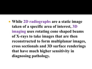
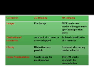
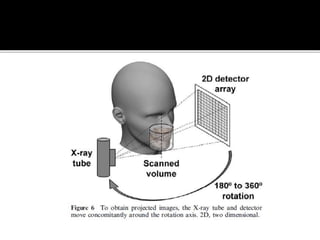
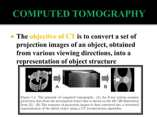
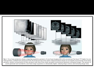
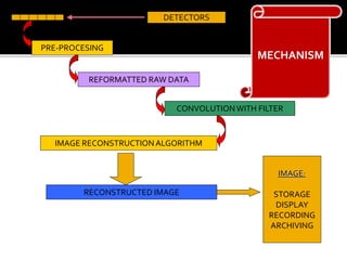
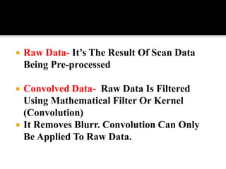
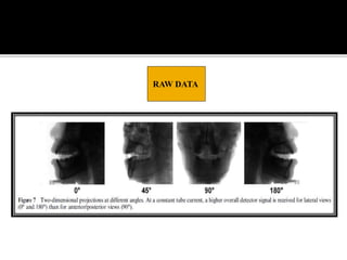
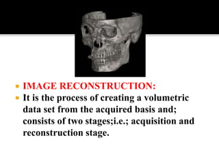
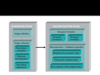
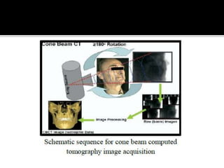
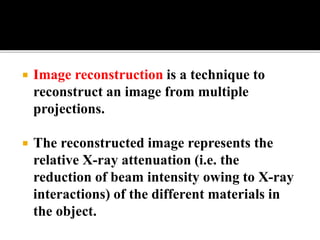
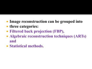
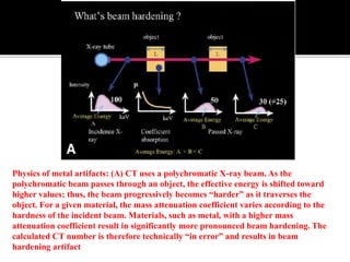
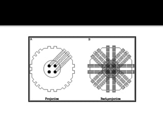
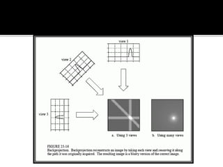
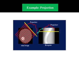
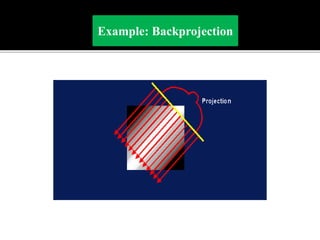
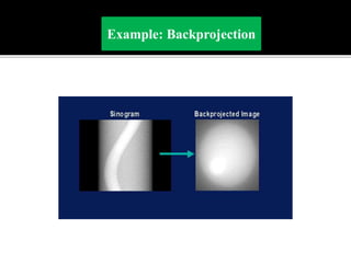
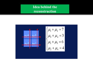
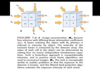
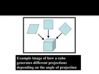
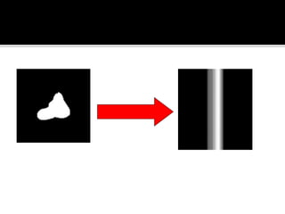
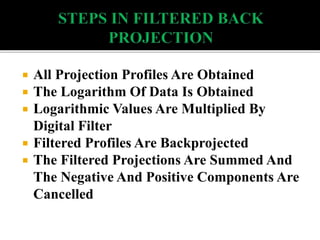
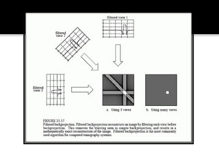
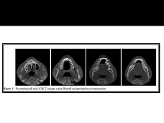
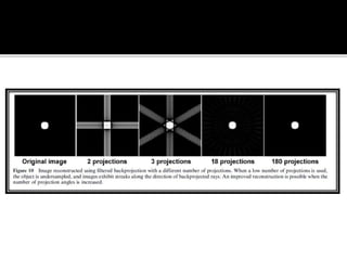
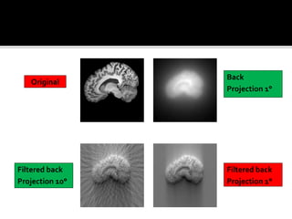
Back projection geometry in cbct

Editor's Notes

  • #3 Improved diagnoses and treatment planning – enhanced images allow you to see more than you can with 2D alone Better patient communication – patients are more likely to comprehend with their diagnosis when the clinician can point out the problem on a more realistic 3D image rather than a static 2D image Increased case acceptance – 3D imaging software allows you to map out treatment plans so patients can make better-informed decisions regarding their proposed treatment plan
  • #6  Hence, the natural capability of X- ray systems is to acquire projection images of the investigated object and these projections can be collected from one or more viewing directions, as desired. The individual images may then be interpreted by a specialist and for a long time, this described examination method, known as projection radiography, was the method commonly used in the practical application
  • #7 Over the last few decades, however, X-ray examination systems have become more and more sophisticated . Electronic control, for instance, allows the user to approach different viewing directions quickly, automatically and with high precision.
  • #10 Images are taken by rotating the equipment 360o round the human body. The amount of radiation emitted is measured by a ring of detectors placed in the gate-shape structure that the patient is introduced in. The image is created from this measures so the internal structure of the human body can be reconstructed from X ray projections. Data is placed inside a matrix in computer's memory, convolving each piece of data with its neighbours using a seed algorithm and FFT, rising each time the resolution of each volume element or voxel. The next step consists on using back-projection which is the opposite to the previous process, storing results in a array.
  • #11 A reduction in the number of views needed will lead to faster and less memory consuming process which will not aect the overall performance of the system. Bsiccaly a tech that would reduce the computational time and increase the accuracy.
  • #17 RAW IMAGES- These images are similar to lateral and posterior-anterior ‘‘cephalometric’’ radiographic images, each slightly offset from one another. 2 Filtered Backprojection Is The Algorithm Used By Modern Ct. It Requires Filtering And Then Backprojection.
  • #21 The acquisition stage involves image collection and detector preprocessing, whereas the reconstruction stage involves sinogram formation and reconstruction using the FDK algorithm.
  • #22 The native, raw data from CBCT acquisition is a series from approximately 100 to over 600 individual 2-D projection frames (basis images) each with over a million pixels with 12- to 16-bits of data assigned to each pixel. This data is then processed to create a volumetric dataset composed of cuboidal volume elements (voxels) by sequence of software algorithms in a process called reconstruction. Subsequent orthogonal images are secondarily generated from the volumetric dataset.
  • #23 Detector sensitivity is ability to respond to small amount of radiation
  • #27 Gray value varies on shade from 0 to 255.
  • #38 Metal artifact results in areas of raw data with low photon count. Fewer photons can traverse metal, because of its higher attenuation.This results in areas of raw data with a lower photon count, which, in turn, contribute to the effect that is perceived as metal artifact. A proprietary adaptive raw data filter that works in all 3 spatial dimensions identifies portions of the raw projection data where there is a disproportionate loss in X-ray signal and applies a local 3D filter with smoothing effect to reduce image noise and streak artifacts.
  • #42 For example, after only three projections, the lines would intersect to yield a “star-pattern”……
  • #44 Sinogram is a visual representation of the raw data in a computed axial tomography
  • #47 The objective of CT image reconstruction is to determine how much attenuation of the narrow x-ray beam occurs in each voxel of the reconstruction matrix. These calculated attenuation values are then represented as gray levels in a 2-dimensional image of the slice (in a manner described later). The 2 voxel dimensions lying in the plane of the slice (X and Y) are often referred to as pixels; however, the sizes of the pixels in the displayed image (referred to as the image matrix) are not necessarily the same as those in the reconstruction matrix but rather may be interpolated from the reconstruction matrix to meet the requirements of the display device or to graphically enlarge (zoom) the image.
  • #48 Ni is the transmitted x-ray intensity for this ray measured by the detector. No is the x-ray intensity entering the subject (patient) for this ray.
  • #53 If we now perform the same operation that we performed earlier with the unfiltered projection, we see that the positive parts of the ima ge re-enforce each other, as do the negative components, but that the positive and negative components tend to cancel each other out.