Downloaded 42 times
![International Journal of Science and Engineering Applications
Volume 2 Issue 7, 2013, ISSN-2319-7560 (Online)
www.ijsea.com 152
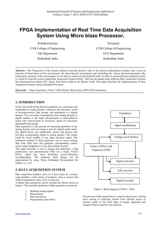
3. COMPONENTS OF DATA
ACQUISTION
The following are the different blocks or components of Data
acquisition system:
1. Transducers
2. Signal conditioning circuits
3. Voltage translators
4. Analog to Digital converter
5. Microblaze
6. GPIO
7. Digital recorders
3.1. Transducers
They convert a physical quantity into an electrical signal which
is acceptable by data acquisition system.
For eg: Platinum RTD which functions on based on positive
temperature coefficient principle can be used to acquire the
temperature.
RT = Ro [1+αo(T - To)]; where Rt is the RTD resistance
for change in temperature.
3.2.Signal conditioning circuit
The signal conditioning is essential as the transducer electrical
output may be in micro or milli volts. Proper signal
conditioning circuitry can be selected depending on transducer.
Fr eg RTD can be connected to a Wheatstone bridge, Capacitive
Transducer can be connected to a OP Amp circuit having a rich
gain factor (β). The strengthened voltage can be connected to
next phase of DAS.
3.3. Voltage Translator
The toughest part of DAS is configuring the voltage levels of
the FPGA with Real time devices. The FPGA contains
expansion headers on board, which are called as GPIO slots. (In
addition GPIO soft IP is also presented in EDK tool.) Through
these Expansion headers the real time devices like ADC; DAC
can be connected in order to acquire physical data by the
Microblaze processor of FPGA. Hence there will be a
requirement of voltage adjustments between FPGA and outside
ADC chip. Virtex 5FPGA supports 3.3 V signals, ADC delivers
5V signals. Appropriate signal conditioning level shifters have
to be selected to overcome this typical phase of DAS
Implementation.
3.2. Analog to Digital Converter
An A/D converter e.g.: ADC0809 is a data acquisition -
successive approximate component is a monolithic CMOS
device with an 8 bit digital out, 8 channel multiplexer, and
microprocessor compatible logic. The working of ADC can be
programmed by the timing signal study where its initiation and
control signals have to program by GPIO of Micro blaze in
Virtex 5.
3.3.Micro blaze
The Micro blaze is a soft processor core designed for Xilinx-
FPGAs from Xilinx. The Embedded development kit [5], [6] is
used to implement hardware design consisting IP cores and a
Microblaze Soft Processor. The DAS design is implemented by
writing the ADC logic in EDK software application to run on
the Microblaze processor. The software application controls the
functionality of different IP cores added to the processor.
SystemC [4] programming language is used for developing
software application
Figure 2. EDK tool flow block dig
3.4. GPIO
A range of applications can be developed with Microblaze
processor. The applications may range from a simple state
machine to Full custom Embedded system. DAS is a full
custom Embedded System, hence it uses UART, GPIO, Timer
& Interrupt controller, External memory along with Microblaze
, The expansion headers provided on FPGA board can be
configured as a channel of communication between GPIO
(target to Microblaze) and ADC 0809. EDK 12.4 tool helps to
provide the communication between the master and slave by
using Base system Builder (BSB) [5]
3.5.Digital Recorders
These records the data obtained by the Microblaze in non-
volatile memory for future reference. Normally UART can be
used as a soft IP for recording the values. This paper
implements the digital display of equivalent temperature
obtained by the Transducer under supervision of Microblaze.
4. IMPLEMENTATION USING MICROBLAZE
The implementation of data acquisition system include
Micro Blaze
User machine interface
Shared memory
A. Micro blaze
Micro blaze is a 32 bit RISC Harward architecture soft core
processor with advanced architecture options i.e., PLB
interface, memory management unit, instruction and data-side
cache, configurable pipeline depth, floating point unit, etc., .it
has over 70-user configurable options, enabling virtually any
processor use case from a very small footprint microcontroller](https://image.slidesharecdn.com/ijsea020710011-130710032821-phpapp02/85/FPGA-Implementation-of-Real-Time-Data-Acquisition-System-Using-Micro-blaze-Processor-2-320.jpg)
![International Journal of Science and Engineering Applications
Volume 2 Issue 7, 2013, ISSN-2319-7560 (Online)
www.ijsea.com 153
to a high performance computive-intensive system running
Linux.[5]
Figure 3. Flow Diagram for FPGA
B .User Machine Interface
The physical interface between FPGA and ADC is made
through a GPIO peripheral IP. A timer peripheral IP is added to
the project to allow the MicroBlaze to measure time delays. A
delay function will be used to create the required signal timing
for the ADC interface.
C. Shared Memory
A Dual Port Block Random Access Memory (DP-BRAM) is the
memory used to store the values of coefficients computed by
Microblaze processor. Block RAM (BRAM) IP Block and XPS
BRAM Controller IP are added to the Microblaze system to
implement Dual Port BRAM.
D. Process Description
The temperatures from two different analog sensors i.e., RTD
are converted to digital form using ADC and the latter is fed to
Microblaze Processor operating at 125 MHz through voltage
translators. To make proper communication with ADC, the
Microblaze processor utilizes General Purpose Input Output
(GPIO) soft IP in a programmed way for sending the signals
from Microblaze and vice versa. The ADC is initiated by one of
the data received by the FPGA is in digital format, which is
processed and the temperature is displayed on screen. Here we
can observe two different parameters are measured
simultaneously.
Figure 4. User machine interface
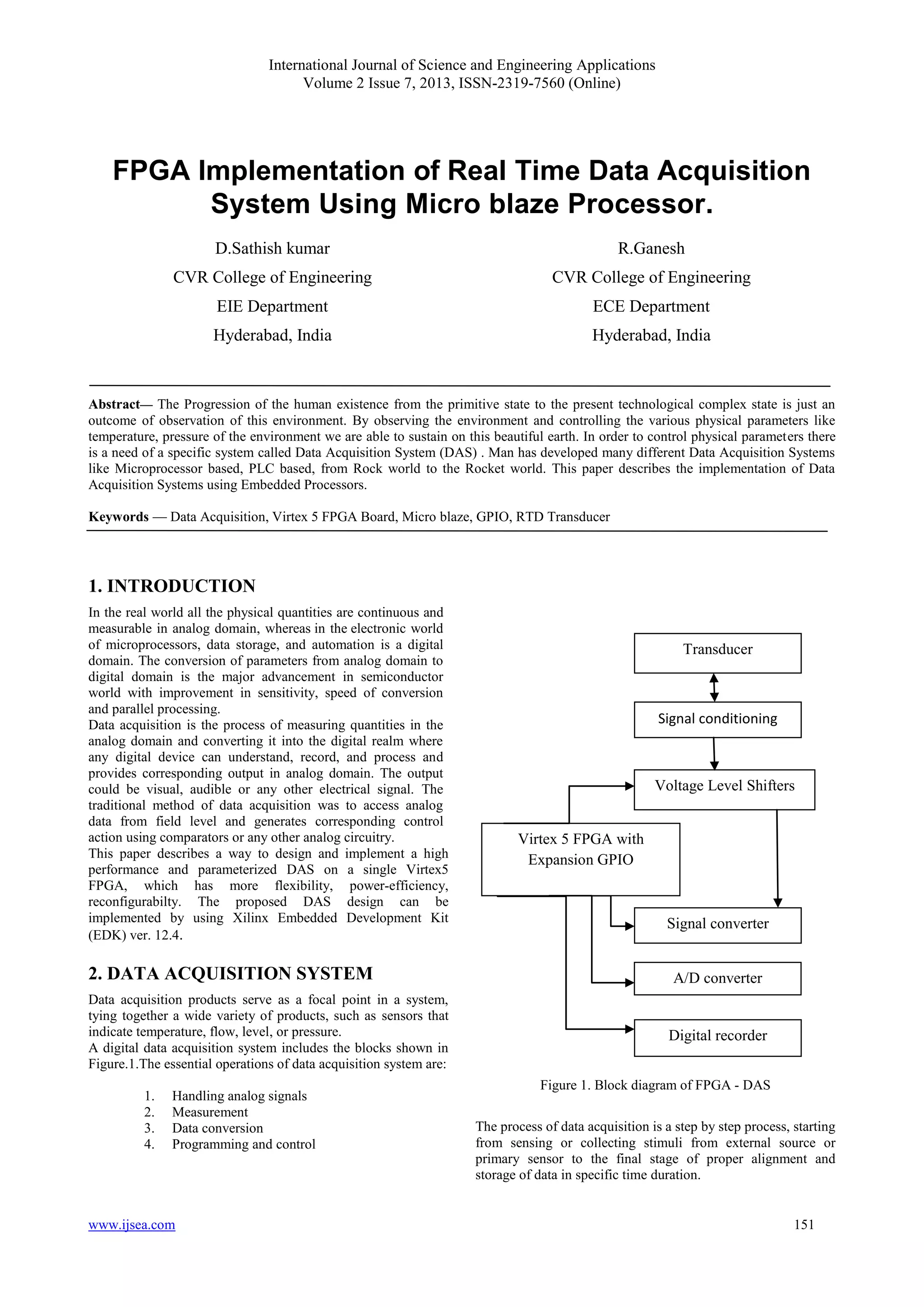
5. RESULTS
The results obtained by the Implementation of DAS using
FPGA are provided in the digital format on the hexadecimal
scale which can be converted into decimal format and displayed
by HyperTerminal. The Table.1 gives the list of temperatures
and their corresponding voltage outputs collected on
HyperTerminal.
Table.1 Temperature and Voltage output values
This data can be stored in a mass storage device like USB
which can be designed as a soft IP on FPGA
Figure 5 Block Diagram of Micro blaze Sub module
Temperature Voltage
(V)
HyperTerminal value
E.O.C D7-D0
61°C 3.83 1 CC
64°C 3.88 1 D0
67°C 3.91 1 D4
70°C 3.93 1 D8
73°C 3.95 1 DC
76°C 3.96 1 E0
79°C 3.98 1 E4
82°C 3.99 1 E8
85°C 4.01 1 EC
88°C 4.21 1 F0
91°C 4.52 1 F4
94°C 4.72 1 F8
97°C 5.03 1 FE](https://image.slidesharecdn.com/ijsea020710011-130710032821-phpapp02/85/FPGA-Implementation-of-Real-Time-Data-Acquisition-System-Using-Micro-blaze-Processor-3-320.jpg)
![International Journal of Science and Engineering Applications
Volume 2 Issue 7, 2013, ISSN-2319-7560 (Online)
www.ijsea.com 154
6. CONCLUSION
The Microblaze processor being a soft-core processor is
added advantage compared to a hard processor which in turn is
costly in terms of reconfiguring it. The programmable input
output lines made it to interface with many of the real-time
applications with the only cost of voltage translators or level
shifters. The high speed clock of soft processor improves the
speed of execution, the added advantage.
The programmable input output lines of FPGA can be used
to interface more number of digital devices and the slots can
also be expanded in order to increase further more number of
digital devices attached. Where for the other type of processors
offers limited connectivity.
7. REFERENCES
[1] Embedded systems tool reference manual” EDK
12.4 version.
[2] Shebli Anvar, Olivier gachelin, Pierre Kestener, Herve Le
Provost, Irakli Mandjavidze,”FPGA – based System-on-
chip Designs for Real-Time Applications in Particle
Physics”,14th
IEEE Real-Time Conference, Stockholm,
Sweden, June 6-10, 2005.
[3] S. Thanee S. Somkuarnpandit and K. Saetang,” FPGA
Based Multi Protocal data Acquisition System with High
Speed USB Interface”.
[4] “Microblaze Processor Reference Guide”, Embedded
Development Kit EDK 12.4 version.
[5] A. Sagahyroon,T.Al-kudairi, “FPGA Based Acquistion of
sensor Data”,InternationalConference on Information. and
Communication Technology, ,ICTTA 2006.
[6] http:/www.xilinx.com/tools/microblaze.html
[7] “Microblaze Processor Reference Guide”](https://image.slidesharecdn.com/ijsea020710011-130710032821-phpapp02/85/FPGA-Implementation-of-Real-Time-Data-Acquisition-System-Using-Micro-blaze-Processor-4-320.jpg)

The document discusses the implementation of a real-time data acquisition system using a MicroBlaze processor on a Virtex 5 FPGA. It elaborates on the components and processes involved in the data acquisition system, including sensors, analog-to-digital conversion, signal conditioning, and the communication between the FPGA and external devices. The results showcase the advantages of using a soft-core processor like MicroBlaze, emphasizing its reconfigurability and high connectivity compared to traditional hard processors.


![Final presentation [dissertation project], 20192 esv0002](https://cdn.slidesharecdn.com/ss_thumbnails/finalpresentationdissertationproject20192esv0002-210613151713-thumbnail.jpg?width=640&height=640&fit=bounds)