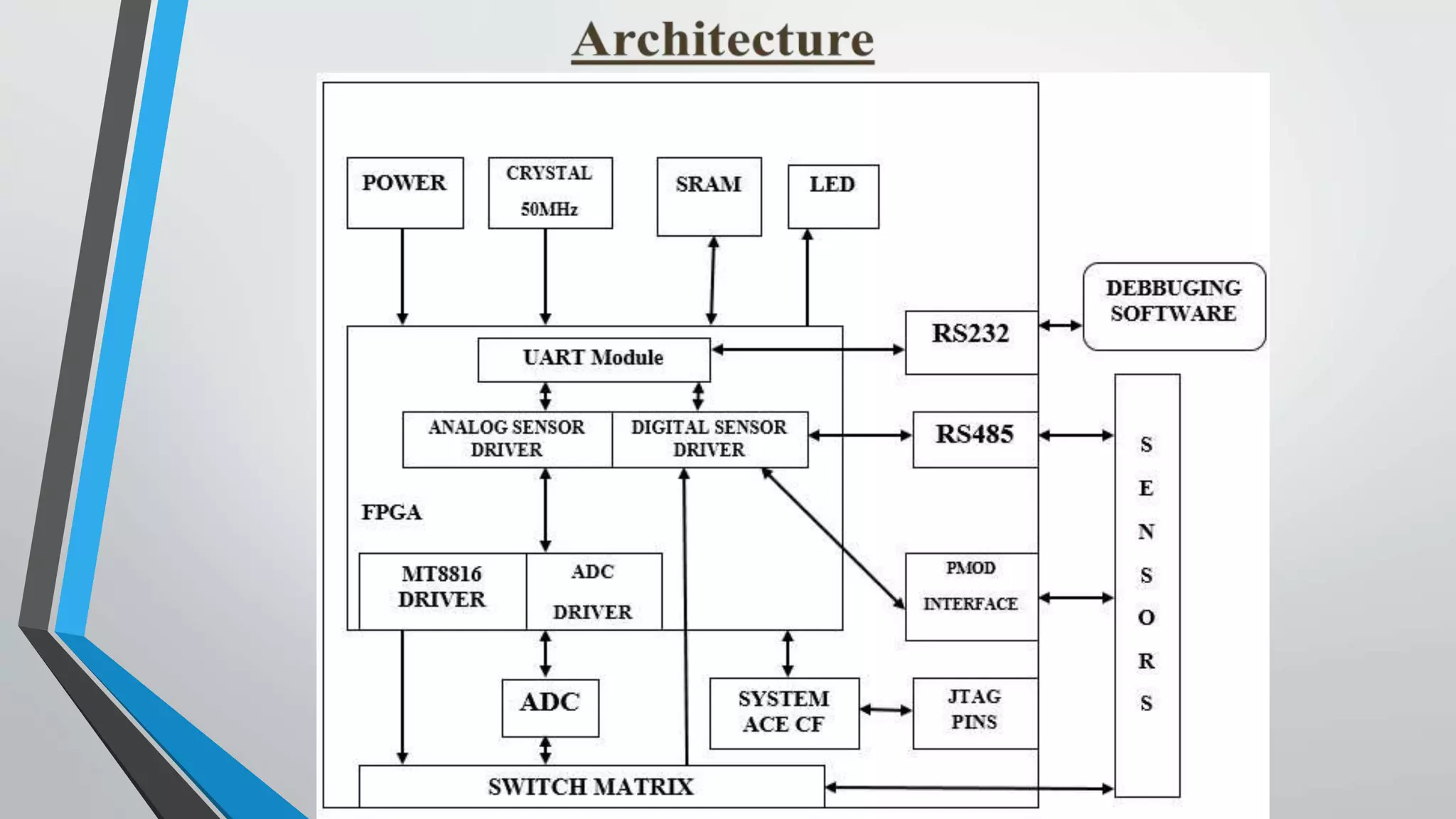
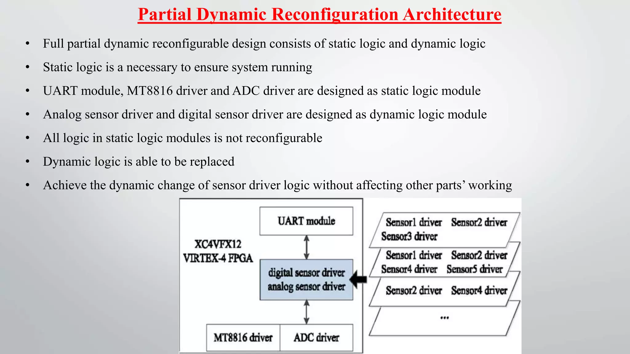
http://aicra.ac.in
Reconfigurable Sensor Data Acquisition
Based on FPGA for Industrial
Computerization Control
Guided By, Presented By,
Prof.Alex V Nishmi Suresh
Dept. of ECE S3,06
M.Tech Embedded System
OVERVIEW
INTRODUCTION
WHAT IS DATAACQUISITION SYSTEM
EVOLUTION OF DATAACQUISITION SYSTEM
PROBLEMS IN DATAACQUISITION
OBJECTIVE
FPGA RECONFIGURATION TECHNOLOGY
ARCHITECTURE
IMPLEMENTATION
ADVANTAGES OF FPGA RECONFIGURATION TECHNOLOGY
CONCLUSION
REFERENCES
PHASE I
Reconfigurable Data Acquisition System
&
Architecture
Introduction
Sensor data acquisition system is an essential part
Variety of sensor producer causes the difficulty of protocol’s unity
Requires the acquisition boards to be powered off when the number or types or
manufacturer of sensors is changed is unreasonable
Proposed to design a reconfigurable data acquisition system for industrial sensors
using FPGA
Both dynamic system reconfiguration and static system reconfiguration
What is Data Acquisition
 Process of measuring an electrical or physical phenomenon such as voltage,
current, temperature, pressure, or sound with a computer.
 Consists of sensors, DAQ measurement hardware, and a computer with
programmable software
Evolution of Data Acquisition System
PC based Data Acquisition
• Involves reading electrical signals into a computer from some form of sensor
• Acquired data may have to be stored, printed or displayed
• Analyzed or processed in some way in order to generate further signals for
controlling external equipment
• Using the PC for data acquisition and control is that there is now a large and
expanding pool of programmers,engineers and scientists who are familiar
with the PC
USB based Data Acquisition
• USB DAQ devices deliver true high-performance
measurements while benefiting from the simplicity and
portability of USB.
• They range from low-cost, single-function devices to high-
performance modular systems
• Ideal for a variety of applications from simple data logging
to embedded OEM systems.
Microcontroller based Data Acquisition
• Low cost user friendly data acquisition system based on 8051 family
microcontroller
• General purpose 8 bit ADC 0809 with 8 analogue inputs is used
• Clock is derived from a simple NE555 circuit
• DAS is designed for 5V DC input for full scale reading
• The data transferred between microcontrollers based DAS and PC is in nibble (4
bit) mode
• Data read by the controlling program is saved in computer files
Arduino based Data Acquisition
• Arduino Microcontroller board is used which has inbuilt ADC and other
peripheral circuitry necessary for operation.
• The physical parameter is sensed by the sensors and is converted into analog
signal.
• This analog signal is fed to the Arduino board ADC pins which is then
converted in to an equivalent digital quantity
• Processed output is displayed on the LCD display or it’s saved in a database
Problems In Data Acquisition
Real time
performance
Universality
of
configuration
Universality
of
function
Continuity
of
working
2
1
3
4
Universality of function
 . Data acquisition system tends to connect to a wide variety of sensors.
 Challenge for the universality of the system.
 Difficult to implement all the sensor protocols in a single system at the same time
Universality of configuration
 Different functional units may use different sensor combinations.
 The download process will be very complex and easy to make mistakes
 When different configuration files are given for different units.
Continuity of working
Replacing sensors is a basic requirement for industrial applications
For instance, adding or reducing the number of sensors
 It is unreasonable to interrupt current work
Power off the whole system in order to change a sensor.
Real-time performance
 Industrial applications often require high real-time performance
 Traditional sensor reading cycle depends more on the embedded
program skills.
Objective
i. System is applied to a real time performance
ii.FPGA is used as the core controller
iii.Architecture is proposed which make the system to achieve
a) Sensor protocol can switched at any time
b) Acquisition board with different function can download with same
configuration file
c) Achieve switching sensor data function, without powering off the
system
FPGA Reconfiguration Technology
FPGA
reconfiguration
technology
Static reconfiguration Dynamic reconfiguration
Global
Dynamic
reconfiguration
Partial
Dynamic
reconfiguration
Static
Reconfiguration
Global Dynamic
Reconfiguration
Partial Dynamic
Reconfiguration
Refers to powering off and reconfiguration FPGA with new
configuration file to exchange the channels connecting relationship
of switch matrix
Allow reconfiguring the entire logic of FPGA without shutting down
Allow reconfiguring specified logic blocks of FPGA while other
parts in keep working without interruption
Cont……
• Xilinx Virtex-4 FPGA is used as core controller
• External sensors are connected to the system through peripheral circuits
• Debugging software is running on the computer
• System communicates through UART serial port
• Sensor drivers, chip drivers and interface drivers are modules
• Communication circuit, switch matrix circuit, ADC, SystemACE CF
reconfigurable circuit, JTAG standard are peripheral circuits
• Switch matrix is used for static reconfiguration
Architecture Explanation
• SystemACE CF and JTAG are used for dynamic reconfiguration.
• Analog and digital sensor driver are used to analyze and acquired analog and
digital sensor data respectively
• Both sensor data can be collected through MT8816 switch matrix
• MT8816 driver is used to control channels’ connecting relationship in switch
matrix.
• Analog sensor data is sent to analog sensor driver after analog-to-digital
conversion by ADS7870
• ADC driver is used to drive ADS7870 chip to achieve analog-to-digital
conversion
• Data of digital sensor can also be acquired by digital sensor driver through
PMOD interface and RS485 communication port.
Static Reconfiguration Architecture
• Sensor drivers and chip drivers in FPGA
• ADC circuit and switch matrix circuit in
peripheral circuit
• Sensors are connected to FPGA through
channels in MT8816 switch matrix
• Analog sensor driver to generate valid
sensor data from analog sensors
• Static reconfiguration is achieved by
controlling switch matrix
Global Dynamic Reconfiguration Architecture
• SystemACE CF can be used for online
reconfiguration of FPGA
• Configuring FPGA via JTAG is also
reserved
• DIP switch is used to select configuration
file stored in CF card
• Button is designed for configuration reset
• Configuration files corresponding to
different sensor application can be stored
or update into the CF card
• Acquisition function can be changed
without shutting off power
Partial Dynamic Reconfiguration Architecture
• Full partial dynamic reconfigurable design consists of static logic and dynamic logic
• Static logic is a necessary to ensure system running
• UART module, MT8816 driver and ADC driver are designed as static logic module
• Analog sensor driver and digital sensor driver are designed as dynamic logic module
• All logic in static logic modules is not reconfigurable
• Dynamic logic is able to be replaced
• Achieve the dynamic change of sensor driver logic without affecting other parts’ working
PHASE II
Implementation
Hardware Implementation
• Xilinx Virtex-4 FPGA is used as core controller
• External sensors are connected to the system through conditioning circuits.
• FPGA changes switch matrix’s connection to make sensors’ signals after conditioned
bridge to corresponding module in terms of signal type
• For digital signals, they are connected to FPGA directly.
• For analog signals, they are connected to ADC first, then to the FPGA
• 8Mb SRAM is equipped in the system, parallel acquisition of multiple sensors data
can used
• The system can also send data to PC via serial port for further monitoring and analysis
Static Reconfiguration Implementation
• Static reconfiguration in system is achieved by using MT8816 switch matrix
• MT8816 is composed of three parts: address decoder, control data latch and an
8*16 analog switch array
• Analog switch array is controlled by row address (AX) and column address (AY)
• On-off state of the selected channel is determined by DATA input
• Sensors can be changed without disassembling hardware equipment or changing
hardware connection.
Global Dynamic Reconfiguration Implementation
• Different situations of sensors’ usage correspond to different sensor drivers’ combinations
respectively
• Then correspond to different configuration files (.bit) respectively
• Configuration files need to be converted to .ace files by iMPACT tool before stored in CF card
• File Xilinx.sys and folder sensors_d (custom named) are generated by .bit files using iMPACT
tool
• Xilinx.sys is used to specify the configuration file path
• And the 8 .ace files are stored in sensors_d folder
• Select .ace files by changing DIP switch, reset FPGA by pushing button and check
reconfiguration status from LEDs
Partial Dynamic Reconfiguration Implementation
• Analog and digital sensor driver are designed as dynamic logic module
• Bus macro is the communication channel
• Connect between static logic module and reconfigurable module and vice versa
• Bus macro located between modules is not only used to connect signals but also
align signals before and after reconfiguration
• Bus macro of Virtex series FPGA is based on slice structure
• Achieve 8-bit data transmission in parallel
Advantages of FPGA Reconfiguration Technology
Allow the FPGA hardware resources in a time multiplexed way
Reduction of cost and power consumption
System flexibility to cope with frequency change in the function of application
Achieve system updating and maintaining online
Conclusion
• FPGA-based reconfigurable data acquisition system for industrial sensors
• System can achieve static reconfiguration through MT8816 switch matrix
• Achieve the effect of multiple sensor data acquisition on a hardware board
without disassembling hardware equipment or changing hardware connection
• The system can also achieve global dynamic reconfiguration and partial dynamic
reconfiguration through SystemACE CF technology
• Dynamic reconfiguration method, the system can use FPGA chip’s logic
resources in the way of time sharing
• The system can change the sensor connecting in the system online.
References
• [1] Shuang Bao, Hairong Yan, Qingping Chi, Zhibo Pang, and Yuying Sun, “FPGA-
Based Reconfigurable Data Acquisition System for Industrial Sensors”, IEEE
Transactions On Industrial Informatics, Vol. 13, No. 4, August 2017
• [2] A. Tisan and J. Chin, “An End-user Platform For FPGA-based Design And Rapid
Prototyping Of Feedforward Artificial Neural Networks With On-chip
Backpropagation Learning,” IEEE Trans. Ind. Informat., vol. 12, no. 3, pp. 1124–
1133, Jun. 2016.
• [3] Q. Chi, H. Yan, C. Zhang, Z. Pang, and L. D. Xu, “A Reconfigurable Smart
Sensor Interface For Industrial WSN In IoT Environment,” IEEE Trans. Ind.
Informat., vol. 10, no. 2, pp. 1417–1425, May 2014
Cont…
• [4] J. Mangala and J. Manikandan, “FPGA Implementation Of Reconfigurable
Modulation System,” in Proc. 2015 Int. Conf. Adv. Comput., Commun. Informat.,
Aug. 2015, pp. 493–500.
• [5] S. Agarwal, A. Rani, V. Singh and A. P. Mittal, "FPGA Based Wireless
Emergency Medical System for Developing Countries," 2015 Annual Global Online
Conference on Information and Computer Technology (GOCICT), Louisville, KY,
2015, pp. 80-84.
• [6] Z. Wang, Y. Yao, L. Chen, F. Li and G. Jin, "A reconfigurable ethernet-based
data acquisition and processing system for particle physics experiments," 2016
IEEE-NPSS Real Time Conference (RT), Padua, 2016, pp. 1-4.
Fpga acquisition

Fpga acquisition

  • 1.
    http://aicra.ac.in Reconfigurable Sensor DataAcquisition Based on FPGA for Industrial Computerization Control Guided By, Presented By, Prof.Alex V Nishmi Suresh Dept. of ECE S3,06 M.Tech Embedded System
  • 2.
    OVERVIEW INTRODUCTION WHAT IS DATAACQUISITIONSYSTEM EVOLUTION OF DATAACQUISITION SYSTEM PROBLEMS IN DATAACQUISITION OBJECTIVE FPGA RECONFIGURATION TECHNOLOGY ARCHITECTURE IMPLEMENTATION ADVANTAGES OF FPGA RECONFIGURATION TECHNOLOGY CONCLUSION REFERENCES
  • 3.
    PHASE I Reconfigurable DataAcquisition System & Architecture
  • 4.
    Introduction Sensor data acquisitionsystem is an essential part Variety of sensor producer causes the difficulty of protocol’s unity Requires the acquisition boards to be powered off when the number or types or manufacturer of sensors is changed is unreasonable Proposed to design a reconfigurable data acquisition system for industrial sensors using FPGA Both dynamic system reconfiguration and static system reconfiguration
  • 5.
    What is DataAcquisition  Process of measuring an electrical or physical phenomenon such as voltage, current, temperature, pressure, or sound with a computer.  Consists of sensors, DAQ measurement hardware, and a computer with programmable software
  • 6.
    Evolution of DataAcquisition System PC based Data Acquisition • Involves reading electrical signals into a computer from some form of sensor • Acquired data may have to be stored, printed or displayed • Analyzed or processed in some way in order to generate further signals for controlling external equipment • Using the PC for data acquisition and control is that there is now a large and expanding pool of programmers,engineers and scientists who are familiar with the PC
  • 7.
    USB based DataAcquisition • USB DAQ devices deliver true high-performance measurements while benefiting from the simplicity and portability of USB. • They range from low-cost, single-function devices to high- performance modular systems • Ideal for a variety of applications from simple data logging to embedded OEM systems.
  • 8.
    Microcontroller based DataAcquisition • Low cost user friendly data acquisition system based on 8051 family microcontroller • General purpose 8 bit ADC 0809 with 8 analogue inputs is used • Clock is derived from a simple NE555 circuit • DAS is designed for 5V DC input for full scale reading • The data transferred between microcontrollers based DAS and PC is in nibble (4 bit) mode • Data read by the controlling program is saved in computer files
  • 9.
    Arduino based DataAcquisition • Arduino Microcontroller board is used which has inbuilt ADC and other peripheral circuitry necessary for operation. • The physical parameter is sensed by the sensors and is converted into analog signal. • This analog signal is fed to the Arduino board ADC pins which is then converted in to an equivalent digital quantity • Processed output is displayed on the LCD display or it’s saved in a database
  • 10.
    Problems In DataAcquisition Real time performance Universality of configuration Universality of function Continuity of working 2 1 3 4
  • 11.
    Universality of function . Data acquisition system tends to connect to a wide variety of sensors.  Challenge for the universality of the system.  Difficult to implement all the sensor protocols in a single system at the same time Universality of configuration  Different functional units may use different sensor combinations.  The download process will be very complex and easy to make mistakes  When different configuration files are given for different units.
  • 12.
    Continuity of working Replacingsensors is a basic requirement for industrial applications For instance, adding or reducing the number of sensors  It is unreasonable to interrupt current work Power off the whole system in order to change a sensor. Real-time performance  Industrial applications often require high real-time performance  Traditional sensor reading cycle depends more on the embedded program skills.
  • 13.
    Objective i. System isapplied to a real time performance ii.FPGA is used as the core controller iii.Architecture is proposed which make the system to achieve a) Sensor protocol can switched at any time b) Acquisition board with different function can download with same configuration file c) Achieve switching sensor data function, without powering off the system
  • 14.
    FPGA Reconfiguration Technology FPGA reconfiguration technology Staticreconfiguration Dynamic reconfiguration Global Dynamic reconfiguration Partial Dynamic reconfiguration
  • 15.
    Static Reconfiguration Global Dynamic Reconfiguration Partial Dynamic Reconfiguration Refersto powering off and reconfiguration FPGA with new configuration file to exchange the channels connecting relationship of switch matrix Allow reconfiguring the entire logic of FPGA without shutting down Allow reconfiguring specified logic blocks of FPGA while other parts in keep working without interruption Cont……
  • 17.
    • Xilinx Virtex-4FPGA is used as core controller • External sensors are connected to the system through peripheral circuits • Debugging software is running on the computer • System communicates through UART serial port • Sensor drivers, chip drivers and interface drivers are modules • Communication circuit, switch matrix circuit, ADC, SystemACE CF reconfigurable circuit, JTAG standard are peripheral circuits • Switch matrix is used for static reconfiguration Architecture Explanation
  • 18.
    • SystemACE CFand JTAG are used for dynamic reconfiguration. • Analog and digital sensor driver are used to analyze and acquired analog and digital sensor data respectively • Both sensor data can be collected through MT8816 switch matrix • MT8816 driver is used to control channels’ connecting relationship in switch matrix. • Analog sensor data is sent to analog sensor driver after analog-to-digital conversion by ADS7870 • ADC driver is used to drive ADS7870 chip to achieve analog-to-digital conversion • Data of digital sensor can also be acquired by digital sensor driver through PMOD interface and RS485 communication port.
  • 19.
    Static Reconfiguration Architecture •Sensor drivers and chip drivers in FPGA • ADC circuit and switch matrix circuit in peripheral circuit • Sensors are connected to FPGA through channels in MT8816 switch matrix • Analog sensor driver to generate valid sensor data from analog sensors • Static reconfiguration is achieved by controlling switch matrix
  • 20.
    Global Dynamic ReconfigurationArchitecture • SystemACE CF can be used for online reconfiguration of FPGA • Configuring FPGA via JTAG is also reserved • DIP switch is used to select configuration file stored in CF card • Button is designed for configuration reset • Configuration files corresponding to different sensor application can be stored or update into the CF card • Acquisition function can be changed without shutting off power
  • 21.
    Partial Dynamic ReconfigurationArchitecture • Full partial dynamic reconfigurable design consists of static logic and dynamic logic • Static logic is a necessary to ensure system running • UART module, MT8816 driver and ADC driver are designed as static logic module • Analog sensor driver and digital sensor driver are designed as dynamic logic module • All logic in static logic modules is not reconfigurable • Dynamic logic is able to be replaced • Achieve the dynamic change of sensor driver logic without affecting other parts’ working
  • 22.
  • 23.
    Hardware Implementation • XilinxVirtex-4 FPGA is used as core controller • External sensors are connected to the system through conditioning circuits. • FPGA changes switch matrix’s connection to make sensors’ signals after conditioned bridge to corresponding module in terms of signal type • For digital signals, they are connected to FPGA directly. • For analog signals, they are connected to ADC first, then to the FPGA • 8Mb SRAM is equipped in the system, parallel acquisition of multiple sensors data can used • The system can also send data to PC via serial port for further monitoring and analysis
  • 24.
    Static Reconfiguration Implementation •Static reconfiguration in system is achieved by using MT8816 switch matrix • MT8816 is composed of three parts: address decoder, control data latch and an 8*16 analog switch array • Analog switch array is controlled by row address (AX) and column address (AY) • On-off state of the selected channel is determined by DATA input • Sensors can be changed without disassembling hardware equipment or changing hardware connection.
  • 25.
    Global Dynamic ReconfigurationImplementation • Different situations of sensors’ usage correspond to different sensor drivers’ combinations respectively • Then correspond to different configuration files (.bit) respectively • Configuration files need to be converted to .ace files by iMPACT tool before stored in CF card • File Xilinx.sys and folder sensors_d (custom named) are generated by .bit files using iMPACT tool • Xilinx.sys is used to specify the configuration file path • And the 8 .ace files are stored in sensors_d folder • Select .ace files by changing DIP switch, reset FPGA by pushing button and check reconfiguration status from LEDs
  • 26.
    Partial Dynamic ReconfigurationImplementation • Analog and digital sensor driver are designed as dynamic logic module • Bus macro is the communication channel • Connect between static logic module and reconfigurable module and vice versa • Bus macro located between modules is not only used to connect signals but also align signals before and after reconfiguration • Bus macro of Virtex series FPGA is based on slice structure • Achieve 8-bit data transmission in parallel
  • 27.
    Advantages of FPGAReconfiguration Technology Allow the FPGA hardware resources in a time multiplexed way Reduction of cost and power consumption System flexibility to cope with frequency change in the function of application Achieve system updating and maintaining online
  • 28.
    Conclusion • FPGA-based reconfigurabledata acquisition system for industrial sensors • System can achieve static reconfiguration through MT8816 switch matrix • Achieve the effect of multiple sensor data acquisition on a hardware board without disassembling hardware equipment or changing hardware connection • The system can also achieve global dynamic reconfiguration and partial dynamic reconfiguration through SystemACE CF technology • Dynamic reconfiguration method, the system can use FPGA chip’s logic resources in the way of time sharing • The system can change the sensor connecting in the system online.
  • 29.
    References • [1] ShuangBao, Hairong Yan, Qingping Chi, Zhibo Pang, and Yuying Sun, “FPGA- Based Reconfigurable Data Acquisition System for Industrial Sensors”, IEEE Transactions On Industrial Informatics, Vol. 13, No. 4, August 2017 • [2] A. Tisan and J. Chin, “An End-user Platform For FPGA-based Design And Rapid Prototyping Of Feedforward Artificial Neural Networks With On-chip Backpropagation Learning,” IEEE Trans. Ind. Informat., vol. 12, no. 3, pp. 1124– 1133, Jun. 2016. • [3] Q. Chi, H. Yan, C. Zhang, Z. Pang, and L. D. Xu, “A Reconfigurable Smart Sensor Interface For Industrial WSN In IoT Environment,” IEEE Trans. Ind. Informat., vol. 10, no. 2, pp. 1417–1425, May 2014
  • 30.
    Cont… • [4] J.Mangala and J. Manikandan, “FPGA Implementation Of Reconfigurable Modulation System,” in Proc. 2015 Int. Conf. Adv. Comput., Commun. Informat., Aug. 2015, pp. 493–500. • [5] S. Agarwal, A. Rani, V. Singh and A. P. Mittal, "FPGA Based Wireless Emergency Medical System for Developing Countries," 2015 Annual Global Online Conference on Information and Computer Technology (GOCICT), Louisville, KY, 2015, pp. 80-84. • [6] Z. Wang, Y. Yao, L. Chen, F. Li and G. Jin, "A reconfigurable ethernet-based data acquisition and processing system for particle physics experiments," 2016 IEEE-NPSS Real Time Conference (RT), Padua, 2016, pp. 1-4.