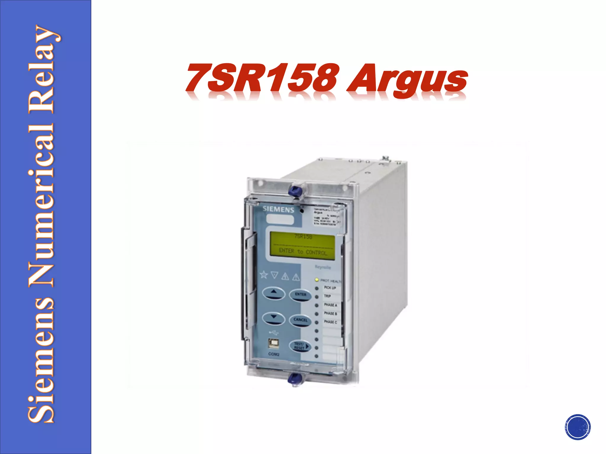
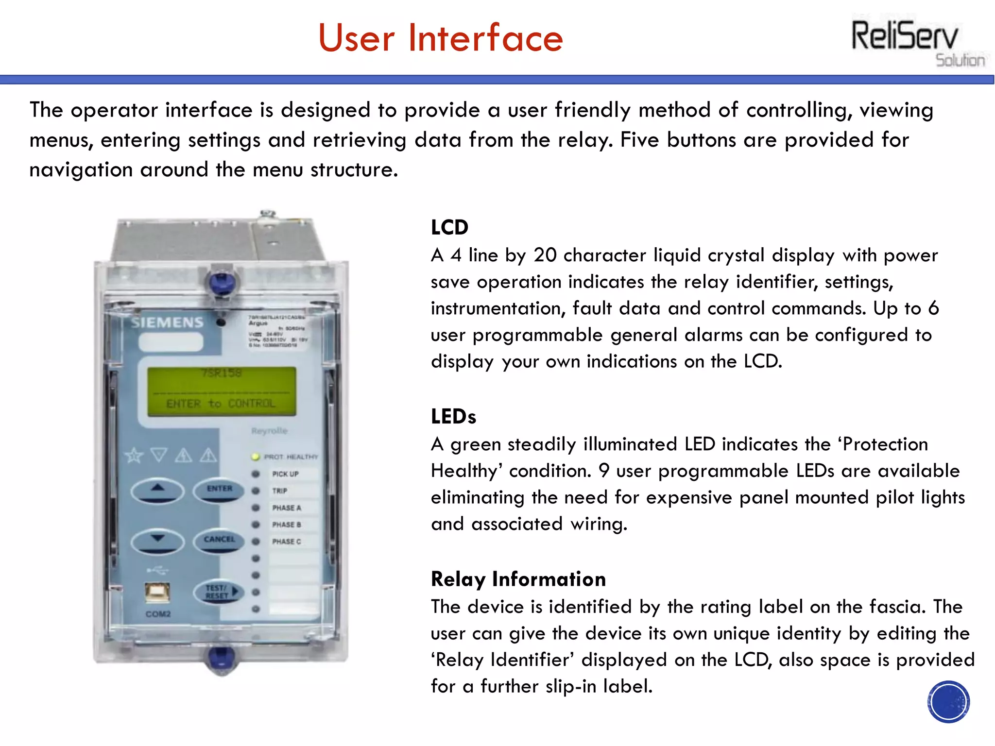
7SR158 Argus
Description
• The 7SR158 is a voltage and frequency protection relay developed to enhance the
Argus family of products by providing a familiar device using the latest generation of
hardware technology.
• Housed in a 4U high, size E4 or E6 (Optional IEC61850 model) case, these relays
provide protection, monitoring, instrumentation and metering with integrated input and
output logic, data logging & fault reports.
• Communication access to the relay functionality is via a front USB port for local PC
connection or rear electrical RS485 port for remote connection & optional IEC61850
communication through two rear Ethernet ports (Electrical or Optical).
Function Overview
Protection (can include)
• 27/59 Under/Over Voltage
• 47 Negative Phase Sequence Voltage
• 59N Neutral Voltage Displacement
• 78 Vector Shift 81 Under/Over Frequency
• 81R Rate-of-Change-of-Frequency (df/dt)
Data Communication
• Standard Communications
Ports Communication access to relay functionality is via a front USB port for local PC connection or
rear electrical RS485 port for remote connection
• Additional Optional Communication Ports
2x Electrical RJ45 Ethernet ports
2x LC Fibre Optic Ethernet ports
• Standard Protocols
IEC60870-5-103, Modbus RTU, DNP3.0. User selectable with programmable data points.
• Optional Protocols
IEC61850 (E6 Case)
• Ethernet Redundancy Protocols:
- Standard in all IEC61850 models:
PRP (Parallel Redundancy Protocol)
RSTP (Rapid Spanning Tree Protocol)
HSR (High-availability Seamless Redundancy)
Function Matrix
Description of Functionality
• 27/59 Under/Over Voltage
Each element has settings for pickup level, drop-off level and Definite Time Lag (DTL)
delay. Operates when voltage exceeds setting for the duration of delay.
• 47 Negative Phase Sequence Voltage
Each element has settings for pickup level and Definite Time Lag (DTL) delays. Operates
when NPS voltage exceeds setting for the duration of delay.
• 59N Neutral Overvoltage
Neutral overvoltage can be used to detect earth faults in high impedance earthed or
isolated systems.
• 74T/CCS Trip & Close Circuit Supervision
The trip or close circuit(s) can be monitored via binary inputs. Detection of trip circuit
failure can be used to raise an HMI alarm (general alarm) and/or output(s).
• 78 Vector Shift
Operates if the voltage vector ‘jumps’ by more than setting during abrupt change in
load.
Description of Functionality
• 81 Under/Overfrequency
Each element has settings for pickup level, drop-off level and Definite Time Lag (DTL) delays.
• 81R Rate of Change of Frequency (df/dt)
Each element has settings for pickup level and Definite Time Lag (DTL) delay.
• Programmable Logic
The user can map binary inputs, protection elements, LEDs and binary outputs together in a logical
scheme.
• Virtual Inputs/Outputs
There are 8 virtual inputs/outputs to provide internal logical states to assist in the application of
the functions.
Control Mode
The relay has a control menu with access to commonly
used command operations. Access to the control
commands is restricted by a 4 character control
function password. Each command requires a select
then execute operation, if the execute operation is not
performed within a time window the command is
aborted.
Serial Communications
• The relay offers a USB serial port as standard on the front of all units. All of the relays
functions can be set on a PC using Reydisp Evolution via the USB port. The connection is made
with a USB cable and operates with a ‘plug and play’ connection, so no pre-setting of the
relay is required. The front port can be switched off or set to use either the DNP3.0, MODBUS-
RTU, IEC60870-5-103 or ASCII protocols for testing purposes.
• A rear RS485 electrical connection is available on all units for system interface connections. An
internal terminating resistor is provided, which can be connected into the circuit by adding a
wire loop between the relevant terminals.
The rear RS485 can be user selected to be OFF, IEC60870-5- 103, MODBUS RTU or DNP3.0
protocol.
Ethernet Communications
• IEC61850 communication is available through an optional EN100 communication module. The
EN100 Module can be ordered with either 2x Electrical RJ45 or 2x Fibre optic LC Ethernet
ports.
• Information on IEC61850 functionality can be found in the following 7SR158 documents:
o Model Implementation Conformance Statement (MICS)
o Protocol Implementation Conformance Statement (PICS)
o Protocol Implementation Extra Information for Testing (PIXIT)
Monitoring Functions
• Primary/Secondary Line and Phase Voltages
• Positive Phase Sequence (PPS) Voltage
• Negative Phase Sequence (NPS) Voltage
• Zero Phase Sequence (ZPS) Voltage
• Frequency Binary Input/Output status
• Time and date Starters
• Fault data Event records
• CB trip and maintenance counters and Time to Trip
User Interface
The operator interface is designed to provide a user friendly method of controlling, viewing
menus, entering settings and retrieving data from the relay. Five buttons are provided for
navigation around the menu structure.
LCD
A 4 line by 20 character liquid crystal display with power
save operation indicates the relay identifier, settings,
instrumentation, fault data and control commands. Up to 6
user programmable general alarms can be configured to
display your own indications on the LCD.
LEDs
A green steadily illuminated LED indicates the ‘Protection
Healthy’ condition. 9 user programmable LEDs are available
eliminating the need for expensive panel mounted pilot lights
and associated wiring.
Relay Information
The device is identified by the rating label on the fascia. The
user can give the device its own unique identity by editing the
‘Relay Identifier’ displayed on the LCD, also space is provided
for a further slip-in label.
Data Acquisition-Via Communication Interface
Sequence of event records
Up to 1000 events are stored and time tagged to 1ms resolution
Fault Records
The last 10 fault records are displayed on the relay fascia and are also available through the
communication interface, with time and date of trip, measured quantities and type of fault.
Waveform recorder
The waveform recorder stores analogue data for all poles and the states of protection
functions, binary inputs, LEDs and binary outputs with user settable pre & post trigger data. A
record can be triggered from protection function, binary input or via data communications.
Demand Metering
A rolling record of demand over the last 24h is stored. The demand is averaged over a user
selectable period of time. A rolling record of such demand averages is stored and provides
the demand history.
Real Time Clock
The time and date can be set and are maintained while the relay is de-energised by a back
up storage capacitor. The time can be synchronized from a binary input pulse or the data
communication channel.
Construction
• The relay is housed in a 4U high size E4 or E6 case with a removable clear plastic fascia
cover. The plastic fascia cover can be ordered with or without two push buttons to allow the
user to view the settings and instruments without removing the cover.
• Two plastic handles are provided to allow the relay to be withdrawn from its case, contacts in
the case ensure that the normally closed contacts remain short circuited when the relay is
withdrawn.
• The rear terminal blocks comprise M4 female terminals for ring crimp wire connections, to
provide a secure and reliable termination.
Reydisp Evolution
• Reydisp Evolution is common to the
entire range of Reyrolle numeric
products. The user can apply settings,
interrogate settings, retrieve events
and fault data.
• Language Editor
The Language editor software gives the user
the ability to customize the text displayed in
the relay menu structure and instrumentation.
The tool allows a language file to be created
and transferred to the relay also containing
Western European characters.
Connection Diagram
Data Communication Interface
Communication Port Front USB Type B Rear RS485 2 wire electrical
IEC61850 optional ports: 2x Electrical RJ45
Ethernet 2x LC Fibre Optic Ethernet
Protocols IEC60870-5-103 MODBUS RTU (Serial)
DNP3.0 O (Serial) IEC61850 - optional
Fibre Optic Ethernet Data Communication
Interface (IEC 61850 Option)
Unit Design
Housing E4 or E6 (see dimension drawing)
Indication 20 Character 4 line Display Relay Healthy LED
9 Tri Coloured User Programmable Self or
Hand Reset LED’s
With-drawable Element Yes
User Interface 5 Navigation Keys
Weight Typical 2.7kg E4 case, 3.65 kg E6 case.
Additional Transport packaging: add 0.4kg
IP Rating installed with cover IP 51 from front
Mob No:
Mr. Piyush Rathi- +91-9819614841
Website:
www.reliservsolution.com
Email-ID:
piyush@reliserv.in
sales1@reliserv.in
Address:
Office No: 9, Space Heights,
Plot No. 53/54 , Sector 34,
Kamothe,Navi Mumbai- 410209
Contact us

7SR158 Argus Relay

  • 1.
  • 2.
    Description • The 7SR158is a voltage and frequency protection relay developed to enhance the Argus family of products by providing a familiar device using the latest generation of hardware technology. • Housed in a 4U high, size E4 or E6 (Optional IEC61850 model) case, these relays provide protection, monitoring, instrumentation and metering with integrated input and output logic, data logging & fault reports. • Communication access to the relay functionality is via a front USB port for local PC connection or rear electrical RS485 port for remote connection & optional IEC61850 communication through two rear Ethernet ports (Electrical or Optical). Function Overview Protection (can include) • 27/59 Under/Over Voltage • 47 Negative Phase Sequence Voltage • 59N Neutral Voltage Displacement • 78 Vector Shift 81 Under/Over Frequency • 81R Rate-of-Change-of-Frequency (df/dt)
  • 3.
    Data Communication • StandardCommunications Ports Communication access to relay functionality is via a front USB port for local PC connection or rear electrical RS485 port for remote connection • Additional Optional Communication Ports 2x Electrical RJ45 Ethernet ports 2x LC Fibre Optic Ethernet ports • Standard Protocols IEC60870-5-103, Modbus RTU, DNP3.0. User selectable with programmable data points. • Optional Protocols IEC61850 (E6 Case) • Ethernet Redundancy Protocols: - Standard in all IEC61850 models: PRP (Parallel Redundancy Protocol) RSTP (Rapid Spanning Tree Protocol) HSR (High-availability Seamless Redundancy)
  • 4.
  • 5.
    Description of Functionality •27/59 Under/Over Voltage Each element has settings for pickup level, drop-off level and Definite Time Lag (DTL) delay. Operates when voltage exceeds setting for the duration of delay. • 47 Negative Phase Sequence Voltage Each element has settings for pickup level and Definite Time Lag (DTL) delays. Operates when NPS voltage exceeds setting for the duration of delay. • 59N Neutral Overvoltage Neutral overvoltage can be used to detect earth faults in high impedance earthed or isolated systems. • 74T/CCS Trip & Close Circuit Supervision The trip or close circuit(s) can be monitored via binary inputs. Detection of trip circuit failure can be used to raise an HMI alarm (general alarm) and/or output(s). • 78 Vector Shift Operates if the voltage vector ‘jumps’ by more than setting during abrupt change in load.
  • 6.
    Description of Functionality •81 Under/Overfrequency Each element has settings for pickup level, drop-off level and Definite Time Lag (DTL) delays. • 81R Rate of Change of Frequency (df/dt) Each element has settings for pickup level and Definite Time Lag (DTL) delay. • Programmable Logic The user can map binary inputs, protection elements, LEDs and binary outputs together in a logical scheme. • Virtual Inputs/Outputs There are 8 virtual inputs/outputs to provide internal logical states to assist in the application of the functions. Control Mode The relay has a control menu with access to commonly used command operations. Access to the control commands is restricted by a 4 character control function password. Each command requires a select then execute operation, if the execute operation is not performed within a time window the command is aborted.
  • 7.
    Serial Communications • Therelay offers a USB serial port as standard on the front of all units. All of the relays functions can be set on a PC using Reydisp Evolution via the USB port. The connection is made with a USB cable and operates with a ‘plug and play’ connection, so no pre-setting of the relay is required. The front port can be switched off or set to use either the DNP3.0, MODBUS- RTU, IEC60870-5-103 or ASCII protocols for testing purposes. • A rear RS485 electrical connection is available on all units for system interface connections. An internal terminating resistor is provided, which can be connected into the circuit by adding a wire loop between the relevant terminals. The rear RS485 can be user selected to be OFF, IEC60870-5- 103, MODBUS RTU or DNP3.0 protocol.
  • 8.
    Ethernet Communications • IEC61850communication is available through an optional EN100 communication module. The EN100 Module can be ordered with either 2x Electrical RJ45 or 2x Fibre optic LC Ethernet ports. • Information on IEC61850 functionality can be found in the following 7SR158 documents: o Model Implementation Conformance Statement (MICS) o Protocol Implementation Conformance Statement (PICS) o Protocol Implementation Extra Information for Testing (PIXIT) Monitoring Functions • Primary/Secondary Line and Phase Voltages • Positive Phase Sequence (PPS) Voltage • Negative Phase Sequence (NPS) Voltage • Zero Phase Sequence (ZPS) Voltage • Frequency Binary Input/Output status • Time and date Starters • Fault data Event records • CB trip and maintenance counters and Time to Trip
  • 9.
    User Interface The operatorinterface is designed to provide a user friendly method of controlling, viewing menus, entering settings and retrieving data from the relay. Five buttons are provided for navigation around the menu structure. LCD A 4 line by 20 character liquid crystal display with power save operation indicates the relay identifier, settings, instrumentation, fault data and control commands. Up to 6 user programmable general alarms can be configured to display your own indications on the LCD. LEDs A green steadily illuminated LED indicates the ‘Protection Healthy’ condition. 9 user programmable LEDs are available eliminating the need for expensive panel mounted pilot lights and associated wiring. Relay Information The device is identified by the rating label on the fascia. The user can give the device its own unique identity by editing the ‘Relay Identifier’ displayed on the LCD, also space is provided for a further slip-in label.
  • 10.
    Data Acquisition-Via CommunicationInterface Sequence of event records Up to 1000 events are stored and time tagged to 1ms resolution Fault Records The last 10 fault records are displayed on the relay fascia and are also available through the communication interface, with time and date of trip, measured quantities and type of fault. Waveform recorder The waveform recorder stores analogue data for all poles and the states of protection functions, binary inputs, LEDs and binary outputs with user settable pre & post trigger data. A record can be triggered from protection function, binary input or via data communications. Demand Metering A rolling record of demand over the last 24h is stored. The demand is averaged over a user selectable period of time. A rolling record of such demand averages is stored and provides the demand history. Real Time Clock The time and date can be set and are maintained while the relay is de-energised by a back up storage capacitor. The time can be synchronized from a binary input pulse or the data communication channel.
  • 11.
    Construction • The relayis housed in a 4U high size E4 or E6 case with a removable clear plastic fascia cover. The plastic fascia cover can be ordered with or without two push buttons to allow the user to view the settings and instruments without removing the cover. • Two plastic handles are provided to allow the relay to be withdrawn from its case, contacts in the case ensure that the normally closed contacts remain short circuited when the relay is withdrawn. • The rear terminal blocks comprise M4 female terminals for ring crimp wire connections, to provide a secure and reliable termination.
  • 12.
    Reydisp Evolution • ReydispEvolution is common to the entire range of Reyrolle numeric products. The user can apply settings, interrogate settings, retrieve events and fault data. • Language Editor The Language editor software gives the user the ability to customize the text displayed in the relay menu structure and instrumentation. The tool allows a language file to be created and transferred to the relay also containing Western European characters.
  • 13.
  • 14.
    Data Communication Interface CommunicationPort Front USB Type B Rear RS485 2 wire electrical IEC61850 optional ports: 2x Electrical RJ45 Ethernet 2x LC Fibre Optic Ethernet Protocols IEC60870-5-103 MODBUS RTU (Serial) DNP3.0 O (Serial) IEC61850 - optional Fibre Optic Ethernet Data Communication Interface (IEC 61850 Option) Unit Design Housing E4 or E6 (see dimension drawing) Indication 20 Character 4 line Display Relay Healthy LED 9 Tri Coloured User Programmable Self or Hand Reset LED’s With-drawable Element Yes User Interface 5 Navigation Keys Weight Typical 2.7kg E4 case, 3.65 kg E6 case. Additional Transport packaging: add 0.4kg IP Rating installed with cover IP 51 from front
  • 15.
    Mob No: Mr. PiyushRathi- +91-9819614841 Website: www.reliservsolution.com Email-ID: piyush@reliserv.in sales1@reliserv.in Address: Office No: 9, Space Heights, Plot No. 53/54 , Sector 34, Kamothe,Navi Mumbai- 410209 Contact us