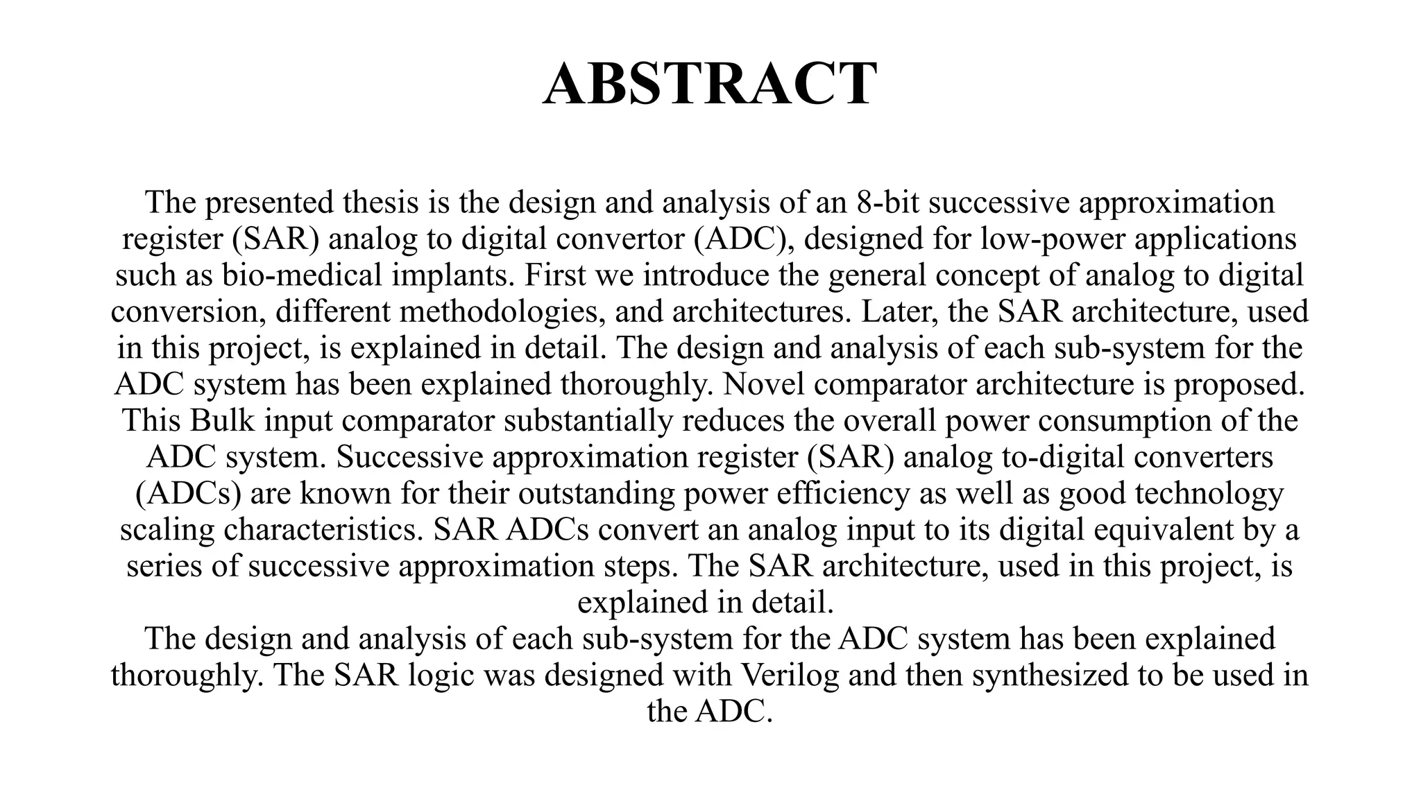
SUCCESSIVE
APPROXIMATION
REGISTER - ADC
PRESENTED BY:
G. CHANDRA SHEKAR - 21EG104D14
M. ARAVIND - 21EG104D24
L. DEEKSHITH - 21EG104D50
UNDER THE GUIDENCE OF
MR.G.ANIL KUMAR
DEPT OF ECE
ABSTRACT
The presented thesis is the design and analysis of an 8-bit successive approximation
register (SAR) analog to digital convertor (ADC), designed for low-power applications
such as bio-medical implants. First we introduce the general concept of analog to digital
conversion, different methodologies, and architectures. Later, the SAR architecture, used
in this project, is explained in detail. The design and analysis of each sub-system for the
ADC system has been explained thoroughly. Novel comparator architecture is proposed.
This Bulk input comparator substantially reduces the overall power consumption of the
ADC system. Successive approximation register (SAR) analog to-digital converters
(ADCs) are known for their outstanding power efficiency as well as good technology
scaling characteristics. SAR ADCs convert an analog input to its digital equivalent by a
series of successive approximation steps. The SAR architecture, used in this project, is
explained in detail.
The design and analysis of each sub-system for the ADC system has been explained
thoroughly. The SAR logic was designed with Verilog and then synthesized to be used in
the ADC.
PROBLEM STATEMENT
In modern digital systems, there is a growing demand for high-performance,
efficient, and accurate conversion of analog signals into digital form. This
conversion is essential in various applications, such as embedded systems, IoT
devices, signal processing, and instrumentation. However, challenges arise in
achieving a balance between resolution, speed, and power consumption in ADC
designs. The Successive Approximation Register ADC, known for its iterative and
efficient approximation mechanism, presents itself as a potential solution.
The task is to design, analyze, and implement a SAR-ADC that:
• Achieves high accuracy with minimal power consumption.
• Operates efficiently within a defined speed range suitable for the application.
• Is capable of handling noise and non-linearity issues to ensure reliable digital
signal representation.
• Meets area and cost constraints for embedded or custom hardware designs.
BLOCK DIAGRAM OF ADC
To better understand a system, engineers divide that system into
different subsystems, which are in turn divided into multiple sections
called blocks. A block diagram is a top-level design which shows the
main components of a system, whether that system be electrical,
mechanical, biological or even chemical. In the field of electronics,
every subsystem in every device has its own block diagram. The block
diagram in analog to digital data conversion consists of four blocks:
Anti-Aliasing Filter
Time Quantization
Level Quantization
Thermal to Binary Convertor
SAR ARCHITECTURE
REFERENCE
[1] J. L. McCreary and P. R. Gray, "All-MOS Charge Redistribution Analog to-
Digital Conversion Techniques-Part I," IEEEJ. Solid-State Circuits, vol. SC-IO,
pp. 371- 379, Dec. 1975.
[2] B. Fotouhi and D. A. Hodges, "High-Resolution AID Conversion in
MOSILSI," IEEE J. Solid-State Circuits, vol. SC-14, pp. 920-926, Dec. 1979.
[3] K. Bacrania, "A 12-Bit Successive-Approximation-Type ADC with Digital
Error Correction," IEEEJ. Solid-State Circuits, vol. SC-21, pp. 10161025, Dec.
1986.
[4] R. K. Hester et al., "Fully Differential ADC with Rail-to-Rail Common
Mode Range and Nonlinear Capacitor Compensation," IEEE J. Solid State
Circuits, vol. SC-25, pp. 173-183, Feb. 1990.
[5] G. A. Miller, "An 18 b 10 JLS Self-Calibrating ADC," ISSCC Dig. Tech. Pap.,
pp. 168-169, Feb. 1990.
[6] W. Black and D. A. Hodges, "Time Interleaved Converter Arrays,
"IEEE J. SolidState Circuits, vol. SC-15, pp. 1022-1029, Dec. 1980.
[7] A. Montijo and K. Rush, "Accuracy in Interleaved ADC Systems," HewlettPackard
J., pp. 38-46, Oct. 1993.
[8] Y. C. Jenq, "Digital Spectra of No uniformly Sampled Signals: Fundamentals and
High-Speed Waveform Digitizers," IEEE Trans. Instrum. Meas., vol. 37, pp. 245- 251,
June 1988.
[9] M. T. McTigue and P. J. Byrne, "An 8-Gigasample/sec 8-Bit Data Acquisition
System for a Sampling Digital Oscilloscope," Hewlett-Packard J., pp. 11-23, Oct.
1993.
[10] C. S. G. Conroy, D. W. Cline, and P. R. Gray, "An 8-b 85-MS/s Parallel Pipelined
AID Converter in I-J.Lrn CMOS," IEEE J. Solid-State Circuits, vol. SC-28, pp. 447-
454, April 1993.
[11] T. L. Brooks, D. H. Robertson, D. F. Kelly, A. Del Muro, and S. W. Harston, “A
cascaded sigma–delta pipeline A/D converter with 1.25 MHz signal bandwidth and 89
dB SNR,” IEEE International Journal of Solid State Circuits, vol. 32, no. 12, pp.
1896–1906,1997.
[12] C. P. Hurrell, C. Lyden, D. Laing, D. Hummerston, and M. Vickery, “An 18 b 12.5 MS/s
ADC with 93 dB SNR,” IEEE International Journal of Solid State Circuits, vol. 45, no. 12,
pp. 2647–2654, 2010.
[13] G. Van der Plas and B. Verbruggen, “A 150 MS/s 133 μW 7 bit ADC in 90 nm
digital CMOS,” IEEE International Journal of Solid State Circuits, vol. 43, no. 12, pp.
2631–2640, 2008.
[14] R. Schreier and G. C. Temes, Understanding Delta–Sigma Data Converters. John
Wiley & Sons, New York, NY, 2005.
[15] C. Toumazou, J. B. Hughes, and N. C. Battersby, “Switched-Currents: an
Analogue Technique for Digital Technology”, Peter Peregrinus, Stevenage, UK, 1993,
ISBN 0-86341-294-7.
[16] N. Tan, “A 1.5-V 3-mW 10-bit 50 MS/s CMOS DAC with Low Distortion and
Low Intermodulation in Standard Digital CMOS Process,” in Proc. of the 1997
IEEE Custom Integrated Circuits Conf. (CICC’97), pp. 599 - 602, Santa Clara, CA,
USA, May 1997.
[17] M. Ismail and T. Fiez, Analog VLSI: Signal and Information Processing,
McGraw-Hill, New York, NY, USA, 1994, ISBN 0-07-113387-9
[18] P. J. Fish, Electronic Noise and Low Noise Design, Macmillan, Basingstoke,
UK, 1993, ISBN 0- 333-57310-2 93
[19] H. Inose, Y. Yasuda and J. Marakami, “A telemetering system by code
modulation, delta-sigma modulation,” IRE Trans. on Space, Electronics and
Telemetry, SET-8, pp. 204-209, Sept. 1962.
[20] W. L. Lee and C. G. Sodini, “A topology for higher order interpolative coders,”
Proc. International Symposium on Circuits and Systems, pp. 459-462, May 1987.
THANK YOU

Presentation 7.pptx successive approximate register

  • 1.
    SUCCESSIVE APPROXIMATION REGISTER - ADC PRESENTEDBY: G. CHANDRA SHEKAR - 21EG104D14 M. ARAVIND - 21EG104D24 L. DEEKSHITH - 21EG104D50 UNDER THE GUIDENCE OF MR.G.ANIL KUMAR DEPT OF ECE
  • 2.
    ABSTRACT The presented thesisis the design and analysis of an 8-bit successive approximation register (SAR) analog to digital convertor (ADC), designed for low-power applications such as bio-medical implants. First we introduce the general concept of analog to digital conversion, different methodologies, and architectures. Later, the SAR architecture, used in this project, is explained in detail. The design and analysis of each sub-system for the ADC system has been explained thoroughly. Novel comparator architecture is proposed. This Bulk input comparator substantially reduces the overall power consumption of the ADC system. Successive approximation register (SAR) analog to-digital converters (ADCs) are known for their outstanding power efficiency as well as good technology scaling characteristics. SAR ADCs convert an analog input to its digital equivalent by a series of successive approximation steps. The SAR architecture, used in this project, is explained in detail. The design and analysis of each sub-system for the ADC system has been explained thoroughly. The SAR logic was designed with Verilog and then synthesized to be used in the ADC.
  • 3.
    PROBLEM STATEMENT In moderndigital systems, there is a growing demand for high-performance, efficient, and accurate conversion of analog signals into digital form. This conversion is essential in various applications, such as embedded systems, IoT devices, signal processing, and instrumentation. However, challenges arise in achieving a balance between resolution, speed, and power consumption in ADC designs. The Successive Approximation Register ADC, known for its iterative and efficient approximation mechanism, presents itself as a potential solution. The task is to design, analyze, and implement a SAR-ADC that: • Achieves high accuracy with minimal power consumption. • Operates efficiently within a defined speed range suitable for the application. • Is capable of handling noise and non-linearity issues to ensure reliable digital signal representation. • Meets area and cost constraints for embedded or custom hardware designs.
  • 4.
    BLOCK DIAGRAM OFADC To better understand a system, engineers divide that system into different subsystems, which are in turn divided into multiple sections called blocks. A block diagram is a top-level design which shows the main components of a system, whether that system be electrical, mechanical, biological or even chemical. In the field of electronics, every subsystem in every device has its own block diagram. The block diagram in analog to digital data conversion consists of four blocks: Anti-Aliasing Filter Time Quantization Level Quantization Thermal to Binary Convertor
  • 6.
  • 7.
    REFERENCE [1] J. L.McCreary and P. R. Gray, "All-MOS Charge Redistribution Analog to- Digital Conversion Techniques-Part I," IEEEJ. Solid-State Circuits, vol. SC-IO, pp. 371- 379, Dec. 1975. [2] B. Fotouhi and D. A. Hodges, "High-Resolution AID Conversion in MOSILSI," IEEE J. Solid-State Circuits, vol. SC-14, pp. 920-926, Dec. 1979. [3] K. Bacrania, "A 12-Bit Successive-Approximation-Type ADC with Digital Error Correction," IEEEJ. Solid-State Circuits, vol. SC-21, pp. 10161025, Dec. 1986. [4] R. K. Hester et al., "Fully Differential ADC with Rail-to-Rail Common Mode Range and Nonlinear Capacitor Compensation," IEEE J. Solid State Circuits, vol. SC-25, pp. 173-183, Feb. 1990. [5] G. A. Miller, "An 18 b 10 JLS Self-Calibrating ADC," ISSCC Dig. Tech. Pap., pp. 168-169, Feb. 1990.
  • 8.
    [6] W. Blackand D. A. Hodges, "Time Interleaved Converter Arrays, "IEEE J. SolidState Circuits, vol. SC-15, pp. 1022-1029, Dec. 1980. [7] A. Montijo and K. Rush, "Accuracy in Interleaved ADC Systems," HewlettPackard J., pp. 38-46, Oct. 1993. [8] Y. C. Jenq, "Digital Spectra of No uniformly Sampled Signals: Fundamentals and High-Speed Waveform Digitizers," IEEE Trans. Instrum. Meas., vol. 37, pp. 245- 251, June 1988. [9] M. T. McTigue and P. J. Byrne, "An 8-Gigasample/sec 8-Bit Data Acquisition System for a Sampling Digital Oscilloscope," Hewlett-Packard J., pp. 11-23, Oct. 1993. [10] C. S. G. Conroy, D. W. Cline, and P. R. Gray, "An 8-b 85-MS/s Parallel Pipelined AID Converter in I-J.Lrn CMOS," IEEE J. Solid-State Circuits, vol. SC-28, pp. 447- 454, April 1993.
  • 9.
    [11] T. L.Brooks, D. H. Robertson, D. F. Kelly, A. Del Muro, and S. W. Harston, “A cascaded sigma–delta pipeline A/D converter with 1.25 MHz signal bandwidth and 89 dB SNR,” IEEE International Journal of Solid State Circuits, vol. 32, no. 12, pp. 1896–1906,1997. [12] C. P. Hurrell, C. Lyden, D. Laing, D. Hummerston, and M. Vickery, “An 18 b 12.5 MS/s ADC with 93 dB SNR,” IEEE International Journal of Solid State Circuits, vol. 45, no. 12, pp. 2647–2654, 2010. [13] G. Van der Plas and B. Verbruggen, “A 150 MS/s 133 μW 7 bit ADC in 90 nm digital CMOS,” IEEE International Journal of Solid State Circuits, vol. 43, no. 12, pp. 2631–2640, 2008. [14] R. Schreier and G. C. Temes, Understanding Delta–Sigma Data Converters. John Wiley & Sons, New York, NY, 2005. [15] C. Toumazou, J. B. Hughes, and N. C. Battersby, “Switched-Currents: an Analogue Technique for Digital Technology”, Peter Peregrinus, Stevenage, UK, 1993, ISBN 0-86341-294-7.
  • 10.
    [16] N. Tan,“A 1.5-V 3-mW 10-bit 50 MS/s CMOS DAC with Low Distortion and Low Intermodulation in Standard Digital CMOS Process,” in Proc. of the 1997 IEEE Custom Integrated Circuits Conf. (CICC’97), pp. 599 - 602, Santa Clara, CA, USA, May 1997. [17] M. Ismail and T. Fiez, Analog VLSI: Signal and Information Processing, McGraw-Hill, New York, NY, USA, 1994, ISBN 0-07-113387-9 [18] P. J. Fish, Electronic Noise and Low Noise Design, Macmillan, Basingstoke, UK, 1993, ISBN 0- 333-57310-2 93 [19] H. Inose, Y. Yasuda and J. Marakami, “A telemetering system by code modulation, delta-sigma modulation,” IRE Trans. on Space, Electronics and Telemetry, SET-8, pp. 204-209, Sept. 1962. [20] W. L. Lee and C. G. Sodini, “A topology for higher order interpolative coders,” Proc. International Symposium on Circuits and Systems, pp. 459-462, May 1987.
  • 11.