Design Technique of Bandpass FIR filter using Various Window Function
•
1 like•324 views

Abstract: Filter is one of the most important part of communication system. Without digital filter we cannot think about proper communication because noise occurs in channel. For removing noise or cancellation of noise we use various type of digital filter. In this paper we propose design technique of bandpass FIR filter using various type of window function. Kaiser window is the best window function in FIR filter design. Using this window we can realize that FIR filter is simple and fast. Keywords: FIR filter, LTI, bandpass filter, MATLAB

Recommended
More Related Content
What's hot
What's hot (20)
Viewers also liked
Viewers also liked (20)
Similar to Design Technique of Bandpass FIR filter using Various Window Function
Similar to Design Technique of Bandpass FIR filter using Various Window Function (20)
More from IOSR Journals
Recently uploaded
Recently uploaded (20)
Design Technique of Bandpass FIR filter using Various Window Function
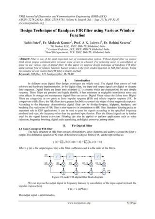
- 1. IOSR Journal of Electronics and Communication Engineering (IOSR-JECE) e-ISSN: 2278-2834,p- ISSN: 2278-8735.Volume 6, Issue 6 (Jul. - Aug. 2013), PP 52-57 www.iosrjournals.org www.iosrjournals.org 52 | Page Design Technique of Bandpass FIR filter using Various Window Function Rohit Patel1 , Er. Mukesh Kumar2 , Prof. A.K. Jaiswal3 , Er. Rohini Saxena4 1 PG Student, ECE , SSET, SHIATS, Allahabad, India 2,4 Assistant Professor, ECE, SSET, SHIATS Allahabad, India 3 Head Of Department , ECE, SSET, SHIATS, Allahabad, India Abstract: Filter is one of the most important part of communication system. Without digital filter we cannot think about proper communication because noise occurs in channel. For removing noise or cancellation of noise we use various type of digital filter. In this paper we propose design technique of bandpass FIR filter using various type of window function. Kaiser window is the best window function in FIR filter design. Using this window we can realize that FIR filter is simple and fast. Keywords: FIR filter, LTI, bandpass filter, MATLAB I. Introduction In different areas digital filter design techniques are widely used. The digital filter consist of both software and hardware implementation. In the digital filter, the input and output signals are digital or discrete time sequence. Digital filters are linear time invariant (LTI) systems which are characterized by unit sample response. These filters are portable and highly flexible. It has minimum or negligible interference noise and other effects. In storage and maintenance digital filters are easier. Digital filters reduce the failure time. Digital filters are categorized in two parts as finite impulse response (FIR) and infinite impulse response (IIR). In comparison to IIR filters, the FIR filters have greater flexibility to control the shape of their magnitude response. According to the frequency characteristics digital filter can be divided-lowpass, highpass, bandpass, and bandstop.The realization of FIR filter is non-recursive in comparison to IIR filter. Bandpass filtering plays an important role in DSP applications. It can be used to pass the signals according to the specified frequency passband and reject the frequency other than the passband specification. Then the filtered signal can be further used for the signal feature extraction. Filtering can also be applied to perform applications such as noise reduction, frequency boosting, digital audio equalizing, and digital crossover, among others. II. Fir Digital Filter 2.1 Basic Concept of FIR filter The basic structure of FIR filter consists of multipliers, delay elements and adders to create the filter’s output. The difference equation of N order of the recursive digital filters (FIR) can be represented as: y (n)= ℎ 𝑛 𝑥(𝑛 − 𝑘)𝑁−1 𝑘=0 = 𝑏 𝑘 N-1 k=0 𝑥(𝑛 − 𝑘) Where, y (n) is the output signal, h(n) is the filter coefficients and k is the order of the filters. Figure.1 N-order FIR digital filter block diagram We can express the output signal in frequency domain by convolution of the input signal x(n) and the impulse response h(n). Y (n) = x (n)*h (n) The output signal is determined as,
- 2. Design Technique of Bandpass FIR filter using Various Window Function www.iosrjournals.org 53 | Page Y(n)=x(0)*h(n)+x(1)*h(n-1)+x(2)*h(n-2)+……..+x(n)h(0) In differential equation, the coefficient 𝑏 𝑘 equals to the successive value h (n) of unit-sample response. The system function H (z) can be expressed as: H (z) = 𝑏 𝑘 𝑁−1 𝑘=0 𝑧−𝑘 H (z) is polynomial of𝑧−1 . This means that all poles are only plotted at the origin of the Z-plane. FIR filters can be designed in different ways, for example window method, frequency sampling method, weighted least squares method, minimax method and equiripple method. Out of these methods, the window technique is most conventional method for designing FIR filters. 2.2 Window function method of FIR filter design The basic design principles of window function are to calculate ℎ 𝑑(n) by the anti-Fourier transform based on the ideal demanded filter frequency response 𝐻 𝑑(𝑒 𝑗𝜔 ). The formula of ℎ 𝑑(n) is shows as ℎ 𝑑(n) = 1 2𝜋 𝐻 𝑑(𝑒 𝑗𝜔 ) 𝜋 −𝜋 Because ℎ 𝑑(n) is infinitely long, we have to deal with it by window function to get to the unit impulse response h (n). Now it is written as h (n) = w(n). ℎ 𝑑 (n) Where w (n) is the window function. Fixed window and adjustable window are the two categories of window function. Blackman window, Hanning, Hamming and rectangular window are mostly used fixed window function. Kaiser window is a type of adjustable window function. 2.2.1 Hanning window The Hanning window is a raised cosine window and can be used to reduce the side lobes while preserving a good frequency resolution compared to the rectangular window. The hanning window is defined as w n = 0.5 1 − cos 2πn M − 1 , for n = 0 to N − 1 0, elsewhere 2.2.2 Hamming window The hamming window is, like the Hanning window, also a raised cosine window. The hamming window exhibits similar characteristics to the Hanning window but further suppress the first side lobe. The hamming window is defined as w n = 0.54 − 0.46cos 2πn N , for n = 0 to N − 1 0, elsewhere 2.2.3 Blackman window The Blackman window is similar to Hanning and Hamming windows. An advantage with Blackman window over other windows is that it has better stop band attenuation and with less pass band ripple. The Blackman window is defined as w n = (0.42 − 0.5cos 2πn N ) + 0.08cos 4πn N , for n = 0 to N − 1 0, elsewhere 2.2.4 Kaiser window The Kaiser window with parameter β is defined as w n = I0 (β 1−(2(n+1) (N+1))2 I0 , 𝑓𝑜𝑟 𝑛 − 0 to N − 1 0, 𝑒𝑙𝑠𝑒𝑤ℎ𝑒𝑟𝑒
- 3. Design Technique of Bandpass FIR filter using Various Window Function www.iosrjournals.org 54 | Page The parameter β determines the shape of the window and thus controls the trade-off between main-lobe width and side-lobe amplitude. III. Fir Filter Design Using Fda Tool The Filter Design and Analysis (FDA) tool works with MATLAB and the signal processing toolbox to provide a complete environment for start to finish filter design. The FDA tool supports many advanced techniques not available in SP tool. FDA tool is used to – design filters, quantize filter, analyze filter, modify existing filter designs, realize simulink models of quantized direct form FIR filters. 3.1 Filter Specifications Table.1 Filter specification Parameters Values Filter Type Bandpass Design method FIR window(β=3.4 for Kaiser window only) Filter order 38,48 Sampling frequency 100 Lower cut-off frequency 10 Upper cut – off frequency 20 In FDA toolbox of MATLAB ,From the table.1 , first choose "Bandpass" in option of "Filter Type", choose "FIR Window " in option of "Design Method", choose " Blackman, hamming, hanning and Kaiser " one by one in option of "Window ", set "Beta" = 3.4 only for kaiser window. Assign "Specify order"=38 and 48 one by one in options of "Filter Order" ; Sampling frequency Fs = 100Hz,Since use the method of window function to design ,only provide band pass lower cutoff frequency fc1=10Hz and band pass cap cut-off frequency fc2=20Hz. After setting, click "Design Filter", will obtain the FIR filter by design. Through the menu options "Analysis", amplitude frequency response and phase frequency response, zero-pole assignment, coefficient of filter and various characteristics of filter can be showed up. IV. Result And Simulation 4.1 Blackman Window From table 1 we analyzed the filter using Blackman window by FDA tool in the MATLAB and the response of the filter is given in figure 2 and 3 respectively at the order 38 and 48. Figure.2 FIR Blackman window (N=38) Figure.3 FIR Blackman window (N=48) 0 5 10 15 20 25 30 35 40 45 -100 -80 -60 -40 -20 0 Frequency (Hz) Magnitude(dB) Magnitude (dB) and Phase Responses -24.7859 -18.8863 -12.9866 -7.087 -1.1874 4.7123 Phase(radians) 0 5 10 15 20 25 30 35 40 45 -100 -80 -60 -40 -20 0 Frequency (Hz) Magnitude(dB) Magnitude (dB) and Phase Responses -32.1278 -25.2973 -18.4667 -11.6362 -4.8057 2.0248 Phase(radians)
- 4. Design Technique of Bandpass FIR filter using Various Window Function www.iosrjournals.org 55 | Page 4.2 Hamming Window We analyzed the filter using Hamming window or fixed widow by FDA tool in the MATLAB and the response of the filter is given in figure 4 and 5 respectively at the order 38 and 48. Figure.4 FIR Hamming window (N=38) Figure.5 FIR Hamming window (N=48) 4.3 Hanning Window We analyzed the filter using Hanning window or fixed widow by FDA tool in the MATLAB and the response of the filter is given in figure 4 and 5 respectively at the order 38 and 48. Figure.6 FIR Hanning window (N=38) Figure.7 FIR Hanning window (N=48) 0 5 10 15 20 25 30 35 40 45 -70 -60 -50 -40 -30 -20 -10 0 Frequency (Hz) Magnitude(dB) Magnitude (dB) and Phase Responses -22.3173 -18.9901 -15.6629 -12.3358 -9.0086 -5.6815 -2.3543 0.9728 Phase(radians) 0 5 10 15 20 25 30 35 40 45 -70 -60 -50 -40 -30 -20 -10 0 Frequency (Hz) Magnitude(dB) Magnitude (dB) and Phase Responses -24.3125 -20.2066 -16.1008 -11.9949 -7.889 -3.7832 0.3227 4.4286 Phase(radians) 0 5 10 15 20 25 30 35 40 45 -100 -90 -80 -70 -60 -50 -40 -30 -20 -10 0 Frequency (Hz) Magnitude(dB) Magnitude (dB) and Phase Responses -15.7207 -13.5524 -11.384 -9.2156 -7.0473 -4.8789 -2.7105 -0.5422 1.6262 3.7946 5.9629 Phase(radians) 0 5 10 15 20 25 30 35 40 45 -100 -90 -80 -70 -60 -50 -40 -30 -20 -10 0 Frequency (Hz) Magnitude(dB) Magnitude (dB) and Phase Responses -23.1414 -20.5444 -17.9474 -15.3505 -12.7535 -10.1565 -7.5595 -4.9626 -2.3656 0.2314 2.8284 Phase(radians)
- 5. Design Technique of Bandpass FIR filter using Various Window Function www.iosrjournals.org 56 | Page 4.4 Kaiser Window We analyzed the filter using Kaiser window by FDA tool in the MATLAB and the response of the filter is given in figure 8 and 9 respectively at the order 38 and 48. Figure.8 FIR Kaiser window (N=38) Figure.9 FIR Kaiser window (N=48) Table.2 Comparison between different window techniques Window technique Order of the filter Width of main lobe No. of side lobes Blackman Window 38 0.085938 9 48 0.066406 13 Hamming Window 38 0.066406 12 48 0.054688 16 Hanning Window 38 0.074219 13 48 0.058594 17 Kaiser (β=3.4) Window 38 0.058594 16 48 0.046875 20 From the table 2 we can see that as the order of the FIR filter increases the number of the side lobes also increases and width of the main lobe is decreased, that it is tending to sharp cut off that is the width of the main lobe decreased. If the width of the main lobe reduces then the number of the side lobes gets increased. So there should be a compromise between attenuation of side lobes and width of main lobe. On comparing all methods, the Blackman has the smallest side lobes at any order but the width of the main lobe is increased. In the Kaiser window for the lower order the width of the major lobe is less than the other windows. The Kaiser window gives best result. Therefore it is most commonly used window for FIR filter design. V. Conclusion Digital filter can play a major role in speech signal processing applications such as, speech filtering, speech enhancement, noise reduction and automatic speech recognition. The kaiser window gives the minimum 0 5 10 15 20 25 30 35 40 45 -70 -60 -50 -40 -30 -20 -10 0 Frequency (Hz) Magnitude(dB) Magnitude (dB) and Phase Responses -14.7356 -11.9792 -9.2228 -6.4665 -3.7101 -0.9537 1.8027 4.5591 Phase(radians) 0 5 10 15 20 25 30 35 40 45 -70 -60 -50 -40 -30 -20 -10 0 Frequency (Hz) Magnitude(dB) Magnitude (dB) and Phase Responses -15.0358 -11.849 -8.6621 -5.4753 -2.2884 0.8984 4.0852 7.2721 Phase(radians)
- 6. Design Technique of Bandpass FIR filter using Various Window Function www.iosrjournals.org 57 | Page mainlobe width 0.046875 for filter order 48 which means this window has less transition width and introduces more ripple. References [1] S. Salivahanan, A. Vallavaraj, C. Gnanaapriya, “Digital Signal Processing”, Tata McGraw-Hill, 2000. [2] Sonika Gupta, Aman Panghal Performance, “Performance Analysis of FIR Filter Design by Using Rectangular, Hanning and Hamming Windows Methods”, International Journal of Advanced Research in Computer Science and Software Engineering Volume 2, Issue 6, June 2012. [3] Chonghua Li, “Design and Realization of FIR Digital Filters Based on MATLAB” ,IEEE 2010. [4] Saurabh Singh Rajput, Dr. S. S. Bhadauria, “Implementation of FIR Filter using Efficient Window Function and its Application in Filtering a Speech Signal”, International Journal of Electrical, Electronics and Mechanical Controls Volume 1, Issue 1, November 2012.