
Recommended
More Related Content
Similar to DSP (T)_Important Topics.pdf
Similar to DSP (T)_Important Topics.pdf (20)
Recently uploaded
Recently uploaded (20)
DSP (T)_Important Topics.pdf
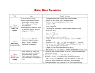
- 1. Digital Signal Processing Unit Topics Sample Questions Unit-1: Introduction to Signals and Systems Classifications of Signals Types of basic signals: Impulse function, Step function, Ramp function, Exponential signal, Sinusoidal signal Basic Operations on Signals: Based on dependent variables, Based on independent variables 1. Explain the classification of signals with suitable examples. 2. Describe the basic signals used in signal processing. 3. Determine the following signals are periodic or not. ( ) ( ) cos5 ( ) ( ) sin 2 i x t t ii x t t 4. Test whether the given signal is an energy signal or a power signal 2 ( ) ( ) ( ) 1 ( ) ( ) ( ) 2 t n i x t e u t ii x n u n 5. Explain the basic operations of signals. Unit-2: Fast Fourier Transform(FFT) Direct evaluation of the DFT Decimation-in-Time algorithm: Radix-2 DIT-FFT algorithm IDFT using FFT algorithm 1. Compute the DFT for the sequence x(n) = {0,1,2,3} using DIT-FFT algorithm. 2. Given x(n)={1, 2, 3, 4, 4, 3, 2, 1}, find X(k) using DIT-FFT algorithm. 3. Find 4-point inverse FFT for the DFT sequence X(k) given as X(k) = {6, - 2+2j, -2, -2-2j} using DIT-FFT algorithm. 4. Compute the IDFT for given sequence using DIT-FFT. ( ) {20, 5.8 2.4,0, 0.17 0.41,0, 0.17 0.41,0, 5.8 2.4} X k j j j j Unit-3: Structure for Discrete-Time systems Block diagram and Signal flow graph representation of linear co- efficient difference equation Basic structures for IIR systems: Direct-form; Cascade form; Parallel form 1. Explain the basic elements required for the block diagram representation of discrete-time systems. 2. Describe the direct form-I and direct form-II structure. 3. Consider a discrete LTI system described by difference equation. ( ) 0.2 ( 1) 0.4 ( 2) 6 ( ) 7.2 ( 1) 1.2 ( 2) y n y n y n x n x n x n Realize the system function using direct form-I and direct form-II. 4. Determine the direct form-II structure for the given transfer function.
- 2. 2 3 2 0.28 0.31 0.04 ( ) 0.5 0.3 0.17 0.2 z z H Z z z z 5. Realize the given transfer function in cascade form. 1 1 2 1 1 4 ( ) 5 1 1 6 6 z H Z z z 6. Realize the given transfer function in parallel form. 1 1 1 1 1 1 1 2 ( ) 1 1 1 1 1 1 8 2 4 z z H Z z z z Unit-4: Filter Design Techniques Design of Discrete-Time IIR filters from continuous time filters IIR Filter design by Impulse invariance and Bilinear transformation Comparisons of IIR and FIR filter 1. Distinguish between FIR and IIR digital filter. 2. Explain how to design a digital IIR filter from analog filter. 3. Obtain H(z) using the impulse invariance method with T=1 sec for the given H(s). 1 ( ) ( 1)( 2) H s s s 4. Write note on frequency warping in IIR filter. 5. Convert the analog filer with system function H(S) into digital filter using bilinear transformation. 2 0.3 ( ) 0.3 16 s H s s 6. Design a digital Butterworth filter satisfying the constraints 0.8 ( ) 1 0 0.2 ( ) 0.2 0.6 j j H e H e with T=1 sec using impulse invariance method.
- 3. 7. Design a Butterworth digital filter to meet the following constraints: 0.9 ( ) 1 0 2 3 ( ) 0.2 4 j j H e H e Use bilinear transformation mapping technique. Assume T=1 sec. 8. The pass band and stop band cut-off frequencies are 350 Hz and 1000Hz respectively. The attenuation at pass band and stop band are -3dB and -10dB respectively. The sampling frequency is 5000Hz. Design a digital low pass Butterworth filter using bilinear transformation. Unit-5: Digital Signal Processor TMS320C5x Key Features Architectural Overview Central Arithmetic Logic Unit (CALU) Parallel Logic Unit (PLU) Auxiliary Register Arithmetic Unit (ARAU) Addressing Modes 1. With neat diagram explain the architecture of TMS320C5x. 2. List the key features of TMS320C5x. 3. Describe the central arithmetic logic unit. 4. Write note on PLU. 5. Explain the addressing modes of TMS320C5x.