Downloaded 285 times

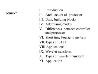
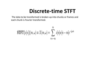
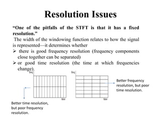
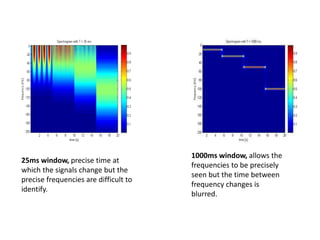
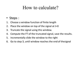
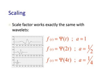
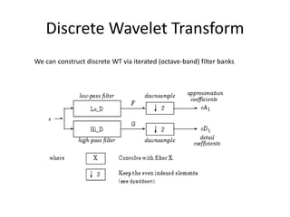
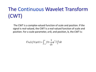
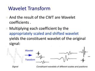
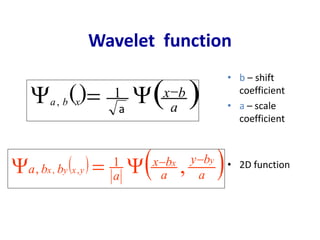
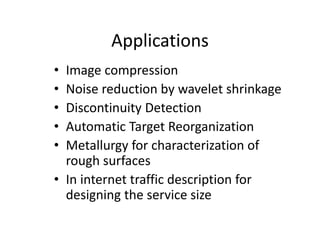


This document covers digital signal processing (DSP) and its applications, highlighting the architecture and components of DSP processors, particularly the TMS320C54x. It explains key concepts like the short-time Fourier transform (STFT) and wavelet transform, including their definitions, applications, and the trade-offs in resolution. The document details various addressing modes, applications of DSP in different industries, and the fundamentals of signal transformation methods.


![Digital Signal Processor ( DSP ) [French]](https://cdn.slidesharecdn.com/ss_thumbnails/lesdsp-121002052639-phpapp01-thumbnail.jpg?width=640&height=640&fit=bounds)