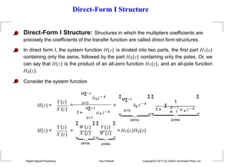
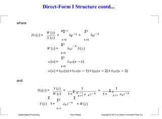
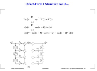
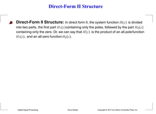
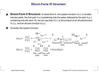
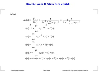
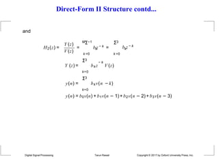
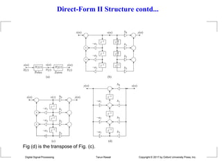
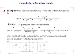
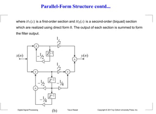
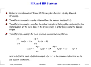
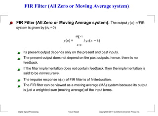
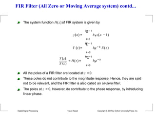
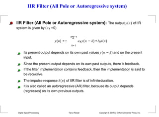
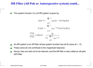
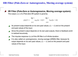
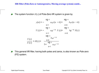
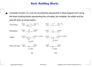
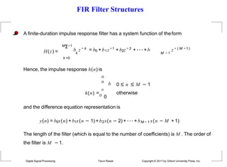
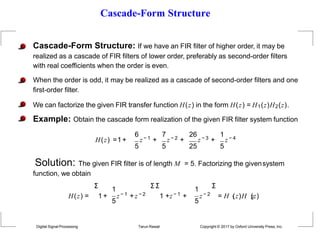
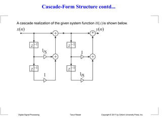
This document discusses different methods for realizing digital filters from their system functions, including FIR, IIR, and pole-zero filters. It describes the difference equation representation and how to obtain the difference equation from the system function. It also covers various filter structures for implementing digital filters, including direct form, cascade form, and linear phase structures. The basic building blocks of digital filters and properties of canonical and transposed structures are also summarized.
![Linear-Phase Structure
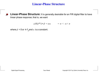
Linear-Phase Structure: It is generally desirable for an FIR digital filter to have
linear phase response; that is, we want
∠H(ejω ) = β − αω − π < ω < π
where β = 0 or ± π and α is a constant.
2
For an FIR digital filter to have linear phase response [Eq. (10.12)], its impulse
response [h(n), 0 ≤ n ≤ M − 1] must be either symmetric or antisymmetric about
some point in time.
Symmetric: h(n) = h(M − 1 − n); β = 0, 0 ≤ n ≤ M − 1
Antisymmetric: h(n) = −h(M − 1− n);
π
β = ± , 0 ≤ n ≤ M − 1
2
Digital Signal Processing Tarun Rawat Copyright © 2017 by Oxford University Press, Inc.](https://image.slidesharecdn.com/chapter10-230925042231-d3f51c08/85/Chapter10-Realization-of-Digital-Filter-pptx-26-320.jpg)
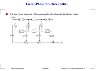
![Linear-Phase Structure contd...
Example:Obtain the linear phase structure for the linear phase FIR system given by
1 1 1 1 1
H(z) =1 + z − 1 + z − 2 + z − 3 + z − 4 + z − 5 +z − 6
2 3 6 3 2
Solution: Consider the given system function [length= M = 7,
order= M − 1 = 6],
Y (z) 1 1 1 1 1
H(z) = = 1 + z − 1 + z − 2 + z − 3 + z − 4 + z − 5 + z − 6
X(z) 2 3 6 3 2
2 3 6
Y (z) = [1 + z − 6 ]X(z) +
1
[z−1 + z− 5 ]X(z) +
1
[z−2 + z− 4 ]X(z) +
1
z − 3 X(z)
1
2
1
3
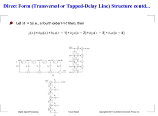
y(n) = [x(n) + x(n − 6)] + [x(n − 1) + x(n − 5)] + [x(n − 2)+ x(n − 4)]+
1
6
Digital Signal Processing Tarun Rawat Copyright © 2017 by Oxford University Press, Inc.
x(n −3)](https://image.slidesharecdn.com/chapter10-230925042231-d3f51c08/85/Chapter10-Realization-of-Digital-Filter-pptx-27-320.jpg)