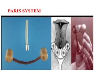
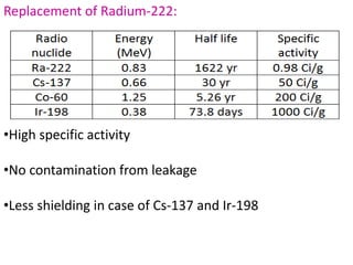
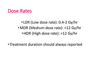
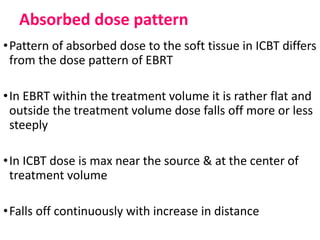
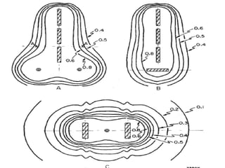
ICRU-38
DR KIRAN KUMAR BR
INTRODUCTION
Intra Cavitary Brachy Therapy
•ICBT- Method of treating tumor by inserting
radioactive source into the natural body cavities
•Used for treatment of cancer of cervix
• Different systems have been proposed for treatment
of cervix cancer
Paris system
Stockholm system
Manchester System
PARIS SYSTEM
•3 vaginal sources- 1 in each lateral fornix & 1 central in
front of the cervical OS
•The ratio of total activity of the vaginal sources to the
activity of the uterine sources should be 1
• A part of Radium is applied in the uterine canal
•Rest is divided into 2 halves and placed in 2 colpostats
applied high up in vaginal vault
•Small quantities of radium applied for a period of 5 days
•Total application amounting to about 8000 mgh
STOCKHOLM TECHNIQUE
•The amount of Radium was unequal
in uterus (30-90 mg, in linear tube)
and in vagina (60-80 mg, in shielded
silver or lead boxes)
•Vaginal applicator is loaded with 53-
88 mg Radium
•Total mg-hrs were usually 6500 to
7100 out of which 4500 mg-hrs
were in vagina.
•Vaginal and uterine applicators were not fixed together
•Fractionated (2-3 applications) delivered within about a
month
•Each application 20-30 hours
•The vaginal applicator is held against the cervix and
fornices by gauze packing
•Uterus packing- multiple small sources called Heyman
capsules
LIMITATIONS
•Treatment specified in terms of mgh of radium
•When combined with EBRT this form of dose
specification is not enough to describe the overall
treatment
• Used intrauterine tubes, which were separate
from the vaginal colpostats. Thus these systems
had a loose geometry.
• Longest possible uterine tubes were preferred to
allow the highest dose to the paracervical tissue
and the pelvic lymph nodes.
MANCHESTER SYSTEM
•Selects reference point in the pelvic cavity for dose
specification
•Criteria for selecting reference points-
Anatomically comparable from patient to patient
Not highly sensitive to small changes in applicator
positions
Allow for correlation of dosage and clinical effects
Calculates dose at 4 points:
•Point A
•Point B
•Bladder point
•Rectum point
Point A:
•2cm lateral to uterine
canal and 2cm superior
to external OS.
•Dose is normalized to
this point
Why Point A:
•A lies on the apex of a triangle called paracervical
triangle formed by uterine canal, uterine artery &
ureter
•Region of early infiltration should not be
underdosaged
•Dose limiting point thus should not be overdosaged
Point B:
•3cm lateral to the point A
•Lies close to pelvic wall
Relevance of Point B:
•Indication of dose fall off in the pelvic region
•Evaluate dose to obturator nodes in that region.
Rectum and Bladder point:
•Bladder and rectum is localized using radiographs
taken with contrast media.
•The maximum dose to bladder and rectum should be
less than the dose to point A.
•80% or less of the dose to point A
Limitations of Point A:
•It relates to the position of the source and not an
anatomical structure
•Dose to it is sensitive to the position of ovoid sources
relative to the tandem sources, which should not be
the determining factor in deciding on implant duration
•depending on the size of the cervix, point A may lie
inside the tumor or outside the tumor
Definitions of Terms and Concepts Currently
Used in ICBT
ICRU-38
•Prescribes dose to target volume instead of
prescribing at a point
•Purpose:
To compare different treatment techniques and
evaluate their merits
To compare the present concepts with historical
series
Derive new clinical and radiological data and
further development of dose specification
Treatment Techniques
Source
•Radium-222
•Cesium-137
•Irridium-192
•Cobalt-60
•Natural source Ra-222 is replaced by artifical
radionuclides
Replacement of Radium-222:
•High specific activity
•No contamination from leakage
•Less shielding in case of Cs-137 and Ir-198
Simulation of linear source
•Linear source are simulated by a set of point
sources
•The linear source simulated by the point source is
longer than the distance between the extreme
point sources
•Linear sources can also be simulated by moving point
source of appropriate activity
•Variations of the type of movement, continuous or
stepwise, of the speed and dwell times of the source at
different positions will modify the shape of the isodose
surfaces
Dose Rates
•LDR (Low dose rate): 0.4-2 Gy/hr
•MDR (Medium dose rate): <12 Gy/hr
•HDR (High dose rate): >12 Gy/hr
•Treatment duration should always reported
LDR Advantages:
• Standardized doses and treatment plan.
- Well defined rules for use exist which allow
optimum implant dosimetry.
• Standardized treatment time.
• Radiobiologically superior.
- Allows continuous radiation to tumor as well as
simultaneous repair of sublethal damage in normal
tissues.
• Less morbidity & best tumor control.
• Cheap.
LDR Disadvantage:
• Inpatient treatment.
• Radiation exposure to staff.
• Spinal or general anaesthesia.
• Need for anti coagualation – due to risk of blood clots
or emboli.
• Geometry and distribution not properly maintained.
• Limited applicability in elderly patients with
respiratory, cardiac problems.
• Individualization & optimization not possible.
MDR Advantages:
• Treatment completed in shorter treatment time.
• Increased patient convenience.
• Considered radiobiologically nearer to LDR
brachytherapy.
HDR Advantages:
• Shorter treatment times, resulting in:
 OPD based treatment possible
 Less patient discomfort (prolonged bed rest is
eliminated )
 Reduced applicator movement during therapy 
geometry well maintained.
 Possibility of treating larger number of patients.
• Allows use of smaller & thinner applicators than
are used in LDR
• Elimination of exposure to personnel.
HDR Disadvantages:
• Decreased therapeutic ratio :
- Short treatment time doesn’t allow repair of sublethal
damage to normal tissues and redistribution &
reoxygenation of tumor cells.
(radiobiologically inferior as normal tissue becomes
more sensitive)
• Multiple sessions  different geometry each time.
• Less time to detect & correct error.
• Limited experience.
• Economic disadvantage : Large capital investment.
• Intense QA and maintainance.
After loading techniques
•Unloaded applicators are introduced into the
patient
•Positioning of applicators are verified radio
graphically using dummy sources
•Sources are inserted manually or remotely
controlled
•Remotely controlled after loading devices (RAL) are now
available that eliminate the direct handling of the
radioactive sources.
•The sources can be instantly loaded and unloaded,
making it possible to provide patient care with the
sources retracted into their shielded position
Advantages of remote after loaders:
1. No radiation hazard.
2. Accurate applicator placement.
- Ideal geometry maintained.
- Dose homogeneity achieved.
- Better dose distribution.
3. Information on source positions available.
4. Individualization & optimization of treatment possible
5. Higher precision , better control.
6. Decreased treatment time  OPD treatment possible
7. Chances of source loss nil .
DISADVANTAGES:
•expensive and require a substantial capital expenditure
for equipment acquisition.
•additional costs must be considered for room shielding
(if not located in an existing shielded facility) and
installing ancillary imaging equipment.
•QA requirements for remote afterloading devices are
significantly greater because of the greater complexity of
the equipment and frequent source changes.
Absorbed-Dose Pattern and Volumes
Absorbed dose pattern
•Pattern of absorbed dose to the soft tissue in ICBT differs
from the dose pattern of EBRT
•In EBRT within the treatment volume it is rather flat and
outside the treatment volume dose falls off more or less
steeply
•In ICBT dose is max near the source & at the center of
treatment volume
•Falls off continuously with increase in distance
Volumes
Target volume
Treatment volume
Reference volume
Irradiated volume
Organs at risk
Target Volume:
•Tissues to be irradiated to a specific absorbed dose
according to a specified time dose pattern
•The target volume should include the demonstrated
tumor and any presumed or microscopic disease.
Treatment volume:
•Volume enclosed by a relevant isodose surface and
encompasses at least target volume
•Target volume is planned inside the treatment volume
Reference volume:
•Volume encompassed by reference isodose surface
•The treatment dose level defining the treatment volume
may be equal to or different from this reference level
•For reporting ICBT it is necessary to determine the
dimensions of the reference volume
Irradiated volume:
•Volume larger than the treatment volume receiving
dose considered significant in relation to tissue
tolerance(50% isodose)
Organ at Risk (OAR):
•Radiosensitive organs in or near target volume which
would influence treatment dose
•Rectum, bladder, ureters and sigmoid colon ar main
OARs in ICBT application for cervix carcinoma.
Specification of Source
Reference Air Kerma Rate:
•The reference air kerma rate of a source is the kerma
rate to air, at a distance of 1m corrected for attenuation
and scattering
•It is expressed in μGy/h at 1m.
Total reference air kerma:
•Sum of product of the reference air kerma rate & the
irradiation time for each source.
TRAK α integral dose to the patient
•Allows to evaluate absorbed dose delivered during
treatment at distances 10-20 cm from the source
Recommendations for reporting
Absorbed doses and Volumes in ICBT
•In EBRT target absorbed dose- absorbed dose at one or
more specification points which are representative of
dose distribution throughout the target volume
•In ICBT –steep dose gradient throughout the tumor or
target volume
•Specification of target dose at a point becomes less
meaningful
•Instead of target dose volume specification is required
Description of the Techniques
The Sources
•Radionuclide
•Reference air kerma rates
•Shape and filtration
Simulation of Linear sources
•When a linear source simulated by set of point sources
the activity of these point sources and their separation
must be indicated
•When moving sources are used
-type of movement
-unidirectional or oscillating movement
-range of movement or oscillation
-speed in different sections of the applicator, or
dwell times of the source at different positions
The Applicator
•The applicator be described including the name of
manufacturer
-rigid or not, consequently with fixed known geometry
or not of the complete applicator
-rigid uterine source with fixed curvature or not
-connection between vaginal and uterine
applicators(fixed, loose or free)
-type of vaginal sources, no., orientation & special
sources (box,ring, etc)
-high Z shielding materials in vaginal applicators or not
Recommendations for Reporting
Total Reference Air Kerma
•Radium used- mgh
•Other radionuclides – mg Radium equivalent is
misleading
•ISL applied to the TRAK allows evaluation of the
absorbed dose delivered at distances from the sources
down to 20-10 cm
•Useful index for radiation protection of personnel
Description of the Reference Volume
Dose level:
•An absorbed dose level of 60Gy is widely accepted as
appropriate reference level for LDR
•When combined with EBRT the isodose level to be
considered is the difference between 60Gy and the dose
delivered at same location by EBRT
•At MDR and HDR dose level equivalent to 60Gy delivered
at LDR
Geometrical measurement of Reference volume:
•Volume is defined by means of 3 dimensions
•Height: maximum dimension along the intrauterine
source & is measured in oblique frontal plane
•Width: maximum dimension perpendicular to the
intrauterine source and is measured in oblique frontal
plane
•Thickness: maximum dimension perpendicular to
intrauterine source & is measured in oblique sagittal
plane
Absorbed dose at reference points
• Determination and specification of absorbed dose
to OAR are useful with respect to normal tissue
tolerance limits
Bladder point
Rectum point
Lymphatic trapezoid of Fletcher
 Pelvic wall points
Bladder point:
•A Foley catheter of 7cc volume is used
•Balloon is filled with radio-opaque fluid
Rectum point:
•On lateral radiograph an AP line is drawn from the lower
end of intrauterine source
•Point is located on this line 5mm behind the posterior
vaginal wall
•Vaginal wall is visualized by radio opacification of vaginal
cavity
•On the AP radiograph rp is marked at lower end of
intrauterine source or middle of the intravaginal source
Lymphatic trapezoid of Fletcher:
Pelvic wall:
Calculation of dose distributions
•Reference volume – dose computed at different
planes
•Two planes
•Oblique frontal plane
•Oblique sagittal plane
•Value in assessing effects in any individual patient
it also provide:
•Compare the methods of specification used in different
centers & of evaluating their respective merits
•Compare the methods of specification used in historical
series with present report recommendations
•Derive new clinical & radiobiological data and
correlations which would improve treatment techniques
and develop further the method of specification
Definition of the 60 Gy Reference
volume in special cases
One linear source only
•In some situations only one linear source is used:
• Narrow vagina with a uterine source protruding into the
vaginal cavity
• Vaginal irradiation with a central source from a cylindrical
applicator
•In estimating the reference volume the width is equal to
the thickness
Vaginal source only
•When only vaginal sources are present
•width is the largest dimension from right to left in an
oblique frontal plane
•Thickness is the largest dimension in a direction
perpendicular to the above oblique plane
•Height is measured along the vaginal axis and is
shorter than other two dimensions
Rigid Applicator
•Fixed connection between vaginal and uterine
sources
•Pre-calculated isodose surfaces can be for given
source loadings
•Pre-calculated dimensions of height , width and
thickness can be given
Time-Dose Pattern
Radiobiological Considerations
•Radiobiological effects (cell death, mutation, etc.,)
depends on dose rate
•Relationship between dose rate and tissue response is
complex since cell distribution, pld repair, reoxygenation
factors should also be taken into account
Recommendations for reporting Time-
Dose Pattern
•Duration of the application should be stated
•When more than one application is performed the
duration of each should be reported as well as the time
intervals between them
•When EBRT and ICBT are combined, the time-dose
schedule of the whole treatment should be reported
Conclusions
•Treatment technique
•TRAK should be stated since it s proportional to dose
delivered to tissues
•Reference volume is described in terms of height, width
and thickness
•Dose at reference points in OARs should be stated
•Dose to reference points in bony structure should be
stated
•Time-dose pattern should be specified
THANK YOU

Icru 38

  • 1.
  • 2.
  • 3.
    Intra Cavitary BrachyTherapy •ICBT- Method of treating tumor by inserting radioactive source into the natural body cavities •Used for treatment of cancer of cervix • Different systems have been proposed for treatment of cervix cancer Paris system Stockholm system Manchester System
  • 4.
  • 5.
    •3 vaginal sources-1 in each lateral fornix & 1 central in front of the cervical OS •The ratio of total activity of the vaginal sources to the activity of the uterine sources should be 1 • A part of Radium is applied in the uterine canal •Rest is divided into 2 halves and placed in 2 colpostats applied high up in vaginal vault •Small quantities of radium applied for a period of 5 days •Total application amounting to about 8000 mgh
  • 6.
    STOCKHOLM TECHNIQUE •The amountof Radium was unequal in uterus (30-90 mg, in linear tube) and in vagina (60-80 mg, in shielded silver or lead boxes) •Vaginal applicator is loaded with 53- 88 mg Radium •Total mg-hrs were usually 6500 to 7100 out of which 4500 mg-hrs were in vagina.
  • 7.
    •Vaginal and uterineapplicators were not fixed together •Fractionated (2-3 applications) delivered within about a month •Each application 20-30 hours •The vaginal applicator is held against the cervix and fornices by gauze packing •Uterus packing- multiple small sources called Heyman capsules
  • 8.
    LIMITATIONS •Treatment specified interms of mgh of radium •When combined with EBRT this form of dose specification is not enough to describe the overall treatment • Used intrauterine tubes, which were separate from the vaginal colpostats. Thus these systems had a loose geometry. • Longest possible uterine tubes were preferred to allow the highest dose to the paracervical tissue and the pelvic lymph nodes.
  • 9.
    MANCHESTER SYSTEM •Selects referencepoint in the pelvic cavity for dose specification •Criteria for selecting reference points- Anatomically comparable from patient to patient Not highly sensitive to small changes in applicator positions Allow for correlation of dosage and clinical effects
  • 10.
    Calculates dose at4 points: •Point A •Point B •Bladder point •Rectum point
  • 11.
    Point A: •2cm lateralto uterine canal and 2cm superior to external OS. •Dose is normalized to this point
  • 12.
    Why Point A: •Alies on the apex of a triangle called paracervical triangle formed by uterine canal, uterine artery & ureter •Region of early infiltration should not be underdosaged •Dose limiting point thus should not be overdosaged
  • 13.
    Point B: •3cm lateralto the point A •Lies close to pelvic wall Relevance of Point B: •Indication of dose fall off in the pelvic region •Evaluate dose to obturator nodes in that region.
  • 14.
    Rectum and Bladderpoint: •Bladder and rectum is localized using radiographs taken with contrast media. •The maximum dose to bladder and rectum should be less than the dose to point A. •80% or less of the dose to point A
  • 15.
    Limitations of PointA: •It relates to the position of the source and not an anatomical structure •Dose to it is sensitive to the position of ovoid sources relative to the tandem sources, which should not be the determining factor in deciding on implant duration •depending on the size of the cervix, point A may lie inside the tumor or outside the tumor
  • 17.
    Definitions of Termsand Concepts Currently Used in ICBT
  • 18.
    ICRU-38 •Prescribes dose totarget volume instead of prescribing at a point •Purpose: To compare different treatment techniques and evaluate their merits To compare the present concepts with historical series Derive new clinical and radiological data and further development of dose specification
  • 19.
  • 20.
  • 21.
    Replacement of Radium-222: •Highspecific activity •No contamination from leakage •Less shielding in case of Cs-137 and Ir-198
  • 22.
    Simulation of linearsource •Linear source are simulated by a set of point sources •The linear source simulated by the point source is longer than the distance between the extreme point sources
  • 23.
    •Linear sources canalso be simulated by moving point source of appropriate activity •Variations of the type of movement, continuous or stepwise, of the speed and dwell times of the source at different positions will modify the shape of the isodose surfaces
  • 24.
    Dose Rates •LDR (Lowdose rate): 0.4-2 Gy/hr •MDR (Medium dose rate): <12 Gy/hr •HDR (High dose rate): >12 Gy/hr •Treatment duration should always reported
  • 25.
    LDR Advantages: • Standardizeddoses and treatment plan. - Well defined rules for use exist which allow optimum implant dosimetry. • Standardized treatment time. • Radiobiologically superior. - Allows continuous radiation to tumor as well as simultaneous repair of sublethal damage in normal tissues. • Less morbidity & best tumor control. • Cheap.
  • 26.
    LDR Disadvantage: • Inpatienttreatment. • Radiation exposure to staff. • Spinal or general anaesthesia. • Need for anti coagualation – due to risk of blood clots or emboli. • Geometry and distribution not properly maintained. • Limited applicability in elderly patients with respiratory, cardiac problems. • Individualization & optimization not possible.
  • 28.
    MDR Advantages: • Treatmentcompleted in shorter treatment time. • Increased patient convenience. • Considered radiobiologically nearer to LDR brachytherapy.
  • 29.
    HDR Advantages: • Shortertreatment times, resulting in:  OPD based treatment possible  Less patient discomfort (prolonged bed rest is eliminated )  Reduced applicator movement during therapy  geometry well maintained.  Possibility of treating larger number of patients. • Allows use of smaller & thinner applicators than are used in LDR • Elimination of exposure to personnel.
  • 30.
    HDR Disadvantages: • Decreasedtherapeutic ratio : - Short treatment time doesn’t allow repair of sublethal damage to normal tissues and redistribution & reoxygenation of tumor cells. (radiobiologically inferior as normal tissue becomes more sensitive) • Multiple sessions  different geometry each time. • Less time to detect & correct error. • Limited experience. • Economic disadvantage : Large capital investment. • Intense QA and maintainance.
  • 32.
    After loading techniques •Unloadedapplicators are introduced into the patient •Positioning of applicators are verified radio graphically using dummy sources •Sources are inserted manually or remotely controlled
  • 33.
    •Remotely controlled afterloading devices (RAL) are now available that eliminate the direct handling of the radioactive sources. •The sources can be instantly loaded and unloaded, making it possible to provide patient care with the sources retracted into their shielded position
  • 35.
    Advantages of remoteafter loaders: 1. No radiation hazard. 2. Accurate applicator placement. - Ideal geometry maintained. - Dose homogeneity achieved. - Better dose distribution. 3. Information on source positions available. 4. Individualization & optimization of treatment possible 5. Higher precision , better control. 6. Decreased treatment time  OPD treatment possible 7. Chances of source loss nil .
  • 36.
    DISADVANTAGES: •expensive and requirea substantial capital expenditure for equipment acquisition. •additional costs must be considered for room shielding (if not located in an existing shielded facility) and installing ancillary imaging equipment. •QA requirements for remote afterloading devices are significantly greater because of the greater complexity of the equipment and frequent source changes.
  • 37.
  • 38.
    Absorbed dose pattern •Patternof absorbed dose to the soft tissue in ICBT differs from the dose pattern of EBRT •In EBRT within the treatment volume it is rather flat and outside the treatment volume dose falls off more or less steeply •In ICBT dose is max near the source & at the center of treatment volume •Falls off continuously with increase in distance
  • 40.
    Volumes Target volume Treatment volume Referencevolume Irradiated volume Organs at risk
  • 41.
    Target Volume: •Tissues tobe irradiated to a specific absorbed dose according to a specified time dose pattern •The target volume should include the demonstrated tumor and any presumed or microscopic disease. Treatment volume: •Volume enclosed by a relevant isodose surface and encompasses at least target volume •Target volume is planned inside the treatment volume
  • 43.
    Reference volume: •Volume encompassedby reference isodose surface •The treatment dose level defining the treatment volume may be equal to or different from this reference level •For reporting ICBT it is necessary to determine the dimensions of the reference volume
  • 44.
    Irradiated volume: •Volume largerthan the treatment volume receiving dose considered significant in relation to tissue tolerance(50% isodose) Organ at Risk (OAR): •Radiosensitive organs in or near target volume which would influence treatment dose •Rectum, bladder, ureters and sigmoid colon ar main OARs in ICBT application for cervix carcinoma.
  • 45.
    Specification of Source ReferenceAir Kerma Rate: •The reference air kerma rate of a source is the kerma rate to air, at a distance of 1m corrected for attenuation and scattering •It is expressed in μGy/h at 1m.
  • 46.
    Total reference airkerma: •Sum of product of the reference air kerma rate & the irradiation time for each source. TRAK α integral dose to the patient •Allows to evaluate absorbed dose delivered during treatment at distances 10-20 cm from the source
  • 47.
    Recommendations for reporting Absorbeddoses and Volumes in ICBT
  • 48.
    •In EBRT targetabsorbed dose- absorbed dose at one or more specification points which are representative of dose distribution throughout the target volume •In ICBT –steep dose gradient throughout the tumor or target volume •Specification of target dose at a point becomes less meaningful •Instead of target dose volume specification is required
  • 49.
  • 50.
    The Sources •Radionuclide •Reference airkerma rates •Shape and filtration
  • 51.
    Simulation of Linearsources •When a linear source simulated by set of point sources the activity of these point sources and their separation must be indicated •When moving sources are used -type of movement -unidirectional or oscillating movement -range of movement or oscillation -speed in different sections of the applicator, or dwell times of the source at different positions
  • 52.
    The Applicator •The applicatorbe described including the name of manufacturer -rigid or not, consequently with fixed known geometry or not of the complete applicator -rigid uterine source with fixed curvature or not -connection between vaginal and uterine applicators(fixed, loose or free) -type of vaginal sources, no., orientation & special sources (box,ring, etc) -high Z shielding materials in vaginal applicators or not
  • 53.
  • 54.
    Total Reference AirKerma •Radium used- mgh •Other radionuclides – mg Radium equivalent is misleading •ISL applied to the TRAK allows evaluation of the absorbed dose delivered at distances from the sources down to 20-10 cm •Useful index for radiation protection of personnel
  • 55.
    Description of theReference Volume Dose level: •An absorbed dose level of 60Gy is widely accepted as appropriate reference level for LDR •When combined with EBRT the isodose level to be considered is the difference between 60Gy and the dose delivered at same location by EBRT •At MDR and HDR dose level equivalent to 60Gy delivered at LDR
  • 56.
    Geometrical measurement ofReference volume: •Volume is defined by means of 3 dimensions •Height: maximum dimension along the intrauterine source & is measured in oblique frontal plane •Width: maximum dimension perpendicular to the intrauterine source and is measured in oblique frontal plane •Thickness: maximum dimension perpendicular to intrauterine source & is measured in oblique sagittal plane
  • 58.
    Absorbed dose atreference points • Determination and specification of absorbed dose to OAR are useful with respect to normal tissue tolerance limits Bladder point Rectum point Lymphatic trapezoid of Fletcher  Pelvic wall points
  • 59.
    Bladder point: •A Foleycatheter of 7cc volume is used •Balloon is filled with radio-opaque fluid
  • 60.
    Rectum point: •On lateralradiograph an AP line is drawn from the lower end of intrauterine source •Point is located on this line 5mm behind the posterior vaginal wall •Vaginal wall is visualized by radio opacification of vaginal cavity •On the AP radiograph rp is marked at lower end of intrauterine source or middle of the intravaginal source
  • 61.
  • 62.
  • 63.
    Calculation of dosedistributions •Reference volume – dose computed at different planes •Two planes •Oblique frontal plane •Oblique sagittal plane •Value in assessing effects in any individual patient
  • 64.
    it also provide: •Comparethe methods of specification used in different centers & of evaluating their respective merits •Compare the methods of specification used in historical series with present report recommendations •Derive new clinical & radiobiological data and correlations which would improve treatment techniques and develop further the method of specification
  • 65.
    Definition of the60 Gy Reference volume in special cases
  • 66.
    One linear sourceonly •In some situations only one linear source is used: • Narrow vagina with a uterine source protruding into the vaginal cavity • Vaginal irradiation with a central source from a cylindrical applicator •In estimating the reference volume the width is equal to the thickness
  • 67.
    Vaginal source only •Whenonly vaginal sources are present •width is the largest dimension from right to left in an oblique frontal plane •Thickness is the largest dimension in a direction perpendicular to the above oblique plane •Height is measured along the vaginal axis and is shorter than other two dimensions
  • 68.
    Rigid Applicator •Fixed connectionbetween vaginal and uterine sources •Pre-calculated isodose surfaces can be for given source loadings •Pre-calculated dimensions of height , width and thickness can be given
  • 69.
  • 70.
  • 71.
    •Radiobiological effects (celldeath, mutation, etc.,) depends on dose rate •Relationship between dose rate and tissue response is complex since cell distribution, pld repair, reoxygenation factors should also be taken into account
  • 72.
  • 73.
    •Duration of theapplication should be stated •When more than one application is performed the duration of each should be reported as well as the time intervals between them •When EBRT and ICBT are combined, the time-dose schedule of the whole treatment should be reported
  • 74.
  • 75.
    •Treatment technique •TRAK shouldbe stated since it s proportional to dose delivered to tissues •Reference volume is described in terms of height, width and thickness •Dose at reference points in OARs should be stated •Dose to reference points in bony structure should be stated •Time-dose pattern should be specified
  • 76.