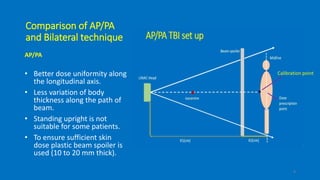
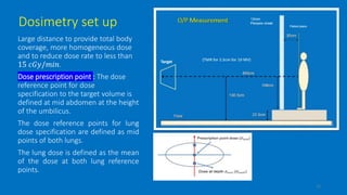
Total body
Irradiation
Bharat D Mistari , DRP 57 , roll no. 20
Introduction
 Total body irradiation ( TBI ) is a form of radiotherapy given as a part
of the treatment (conditioning) with chemotherapy prior to a bone
marrow transplant ( BMT ).
 Why TBI ?
• This procedure reduces the risk of the transplant rejected by patient
body.
• TBI results in immunosuppression, which helps to prevent the failure
of the graft.
• It destroys any residual cancer cell and allows bone marrow cells to
seed and grow.
2
Technical aspect of TBI
• All TBI techniques use MV photon beams that are produced by
I. Cobalt 60 machines
II. LINAC’s
• Beams used in TBI procedure
Stationary, with large field sizes of the order of 70 × 200 𝑐𝑚2
encompassing the whole patient.
Moving, with small field sizes in some sort of translational or rotational
motion to cover the whole patient with radiation beam.
3
Technical aspect of TBI
• AAPM report no 17
• Reviews methods of producing the
very large fields needed for TBI and
other large field procedures.
• Gives recommendation's regarding
dosimetric measurements that are
required prior to such procedures
4
Technical aspects of TBI
• High dose TBI : with MV photon
beams uses total doses ranging
from 300 𝑐𝐺𝑦 𝑡𝑜 1000 𝑐𝐺𝑦 in
single fraction.
• lymphocytic cell kill – to allow
engraftment of donor marrow
• Accuracy of dose delivery should
be within ±5 %
• Low dose TBI : with MV photons
giving about 10 𝑡𝑜 15 𝑐𝐺𝑦 per
day for 10 to 15 days.
• Eradication of malignant cells,
Leukemia, lymphomas, & some
solid tumors.
• Accuracy of dose delivery should
be within ±5 %
5
Irradiation methods of TBI
1. Dedicated facilities designed specifically for treatment with large fields.
• Dedicated facility with single source: field size at 90 cm is 50 × 160 𝑐𝑚2and
field size at 150 cm is 83 × 265 𝑐𝑚2 .
• Dedicated facility with dual source: two cobalt unit can be arranged to get
parallel opposed field at 3 m.
2. Facilities designed for conventional treatments but modified to produce very
large fields.
3. Facilities designed for conventional treatments but using unconventional
geometries to provide the desired field sizes.
6
Irradiation methods of TBI
TBI techniques in which patient and beams are
stationary
A: Two vertical beams.
B: One vertical beam.
C: One horizontal beam, patient in supine position.
D: One horizontal beam, patient standing or sitting.
E: One horizontal beam; patient in lateral decubitus
position.
Some of the small-field TBI techniques in which
patient or beam moves.
F: Source scans horizontally.
G: Patient moves horizontally.
H: Sweeping beam.
7
Comparison of AP/PA
and lateral technique
Lateral
• Less dose uniformity along
longitudinal axis compared to
AP/PA.
• Greater variation in body
thickness along the path of the
beam.
• More comfortable to the
patient if seated or lying down.
• To ensure sufficient skin dose
beam spoiler is used it brings
the surface dose to at least 90%
of the prescribed TBI dose.
8
Comparison of AP/PA
and Bilateral technique
AP/PA
• Better dose uniformity along
the longitudinal axis.
• Less variation of body
thickness along the path of
beam.
• Standing upright is not
suitable for some patients.
• To ensure sufficient skin
dose plastic beam spoiler is
used (10 to 20 mm thick).
9
Calibration point
Choice of irradiation technique
• Available equipment
• Photon beam energy
• Maximum possible field size
• Treatment distance
• Dose rate
• Patient dimension
• Need to selectively shield certain body structures.
10
Selection of large field
technique
• Higher energy lower the dose
variation.(excluding effect of build up
region and tissue inhomogeneities )
• Larger treatment distance lower the
dose variation.
• Larger patient diameter larger dose
variation.
• AP/PA will yield variation not larger
than 15% for most of MV energies and
distances.
• Lateral opposed beams will usually
give greater dose variation compared
to AP/PA for adult patient.
11
Dosimetry set up
Large distance to provide total body
coverage, more homogeneous dose
and to reduce dose rate to less than
15 𝑐𝐺𝑦/𝑚𝑖𝑛.
Dose prescription point : The dose
reference point for dose
specification to the target volume is
defined at mid abdomen at the height
of the umbilicus.
The dose reference points for lung
dose specification are defined as mid
points of both lungs.
The lung dose is defined as the mean
of the dose at both lung reference
points.
12
Phantom dosimetry…
• Water as phantom material is recommended(TG 29), polystyrene and
acrylic can also be used (transfer dose in plastic to dose in water using CF).
• 𝐶𝐹 =
𝜇 𝑒𝑛
𝜌 𝑤𝑎𝑡𝑒𝑟
𝜇 𝑒𝑛
𝜌 𝑝𝑙𝑎𝑠𝑡𝑖𝑐
• CF changes due to huge amount of scattering in large phantom, least error
will be produced if water is used. X rays from LINAC, change in CF are
smaller.
• Determine absolute calibration of the radiation beam using the large field
geometry and largest phantom size available.
• Minimum phantom size for calibration purposes is 30 × 30 × 30 𝑐𝑚3and
that whenever possible additional material is placed around this phantom.
13
Phantom dosimetry…
• To achieve full scattering condition.
• The determination of dose in this phantom of limited size will have to
be corrected to obtain data for full scattering condition.
• Why correction to dose measured ?
TG 21 recommends that the size of a dosimetry phantom should
provide a 5 cm margin on all 4 sides of the largest field size used and
depth sufficient to provide maximum backscatter at the point at
which the dose determination is made.
According to above statement TBI phantom side would be (200 ×
50 × 40 𝑐𝑚3, ≈ 400 𝑘𝑔 ) not practical for routine use.
14
15
Dosimetry
• Output (i.e. dose rate of the beam)
• PDD( )
• TMR
• Output Factor
• Beam profiles – Flatness & Symmetry
• Corrections for patient size and surface irregularity
• Compensators for missing tissues
• Inhomogeneities corrections
• Compensators are required to achieve dose uniformity along the body axis to within
±10%, although extremities and some noncritical structures may exceed this specification.
• Preparation of shielding blocks (lung block): lung blocks are made of Cerrobend it can reduce
lung dose ≈ 60% 𝑜𝑓 𝑝𝑟𝑒𝑠𝑐𝑟𝑖𝑏𝑒𝑑 𝑑𝑜𝑠𝑒.
Dose calculation
𝐷
𝑀𝑈
= 𝛼 ⋅ 𝑆𝑐 𝑟𝑐 ⋅ 𝑆 𝑝 𝑟𝑝 ⋅ 𝑇𝑀𝑅 𝑑, 𝑟𝑝 ⋅
𝑓
𝑓′
2
⋅ 𝑂𝐴𝑅 𝑑 ⋅ 𝑇𝐹
Where
𝑟𝑐 : field size at collimator setting
𝑟𝑝 : field size at patient surface
d : prescription depth or mid line depth at umbilicus level.
TF : transmission factor for spoiler screen and tray (ration of o/p with to
without spoiler )
𝛼 : dose rate (𝑐𝐺𝑦/𝑀𝑈) under standard calibration set up
𝑓 : source to chamber distance under standard calibration set up
𝑓′ : source to body axis distance
16
In vivo dosimetry In vivo patient dose can be measured
with TLD or diodes.
 The TLD response is calibrated to
determine absolute doses.
 To obtain dose at 𝑑 𝑚𝑎𝑥 the dosimeters
should have sufficient tissue equivalent
build up (1.2 cm wax).
 Exit dosimeter readings should be
corrected for the lack of backscatter if
they are to be used for determination
of mid-plane doses.
TLDs remains in place for both the
anterior and posterior fields, to give
the sum of the entry and exit doses.
With the exception of the chest points.
17
• Measured and expected doses should agree to within ±5%, Dose uniformity on the
patient should be within ±10%.
• Radiation induced cable currents are known to be ∝ to the length of cable irradiated
and dose build up within cable leads to net removal of charge.
• This effect can be reduced by factor of 20 by placing full build up material over the
cable, very small volume ionisation chamber should be avoided.
• In-air measurement tend to cofounded by scatter from the wall and floor of the
treatment room (hence TAR is avoided) and PDD or TMR in selected geometry should
be used.
• The depth of measurement in plastic phantom will have to scaled to derive an
equivalent depth in water using TG 21, dose in build up region is strongly dependent
on the treatment geometry (field size, SSD). To measure dose in build-up region
parallel plate chamber has to be used.
Early side effects observed,
• Skin >>
skin is more sensitive and may become red
or pink similar to sunburn.
• Tiredness >>
patient may begin to feel quite tired and
may feel the need to sleep for long period
(hypersomnolence).
• Hair loss >>
patient may loss hairs about fifteen days
after TBI procedure (this includes all body
hairs).
• Nausea and vomiting >>
patient may feel sick (anti sickness drugs
will be prescribed, drink plenty of fluids)
• Diarrhoea >>
condition of having at least three loose,
liquid, or watery bowel movement each
day.
• Sore mouth >>
Inside of patient mouth and throat may
become swollen and sore causing changes
in taste and difficulty in swallowing.
• Bone marrow depression >>
low red cell count prone to anaemia, low
white cell count prone to infection, low
platelets prone to bleeding.
19
Some more pics stolen from many ppts. 
20
Thank you for your time…. 

Total body irradiation

  • 1.
    Total body Irradiation Bharat DMistari , DRP 57 , roll no. 20
  • 2.
    Introduction  Total bodyirradiation ( TBI ) is a form of radiotherapy given as a part of the treatment (conditioning) with chemotherapy prior to a bone marrow transplant ( BMT ).  Why TBI ? • This procedure reduces the risk of the transplant rejected by patient body. • TBI results in immunosuppression, which helps to prevent the failure of the graft. • It destroys any residual cancer cell and allows bone marrow cells to seed and grow. 2
  • 3.
    Technical aspect ofTBI • All TBI techniques use MV photon beams that are produced by I. Cobalt 60 machines II. LINAC’s • Beams used in TBI procedure Stationary, with large field sizes of the order of 70 × 200 𝑐𝑚2 encompassing the whole patient. Moving, with small field sizes in some sort of translational or rotational motion to cover the whole patient with radiation beam. 3
  • 4.
    Technical aspect ofTBI • AAPM report no 17 • Reviews methods of producing the very large fields needed for TBI and other large field procedures. • Gives recommendation's regarding dosimetric measurements that are required prior to such procedures 4
  • 5.
    Technical aspects ofTBI • High dose TBI : with MV photon beams uses total doses ranging from 300 𝑐𝐺𝑦 𝑡𝑜 1000 𝑐𝐺𝑦 in single fraction. • lymphocytic cell kill – to allow engraftment of donor marrow • Accuracy of dose delivery should be within ±5 % • Low dose TBI : with MV photons giving about 10 𝑡𝑜 15 𝑐𝐺𝑦 per day for 10 to 15 days. • Eradication of malignant cells, Leukemia, lymphomas, & some solid tumors. • Accuracy of dose delivery should be within ±5 % 5
  • 6.
    Irradiation methods ofTBI 1. Dedicated facilities designed specifically for treatment with large fields. • Dedicated facility with single source: field size at 90 cm is 50 × 160 𝑐𝑚2and field size at 150 cm is 83 × 265 𝑐𝑚2 . • Dedicated facility with dual source: two cobalt unit can be arranged to get parallel opposed field at 3 m. 2. Facilities designed for conventional treatments but modified to produce very large fields. 3. Facilities designed for conventional treatments but using unconventional geometries to provide the desired field sizes. 6
  • 7.
    Irradiation methods ofTBI TBI techniques in which patient and beams are stationary A: Two vertical beams. B: One vertical beam. C: One horizontal beam, patient in supine position. D: One horizontal beam, patient standing or sitting. E: One horizontal beam; patient in lateral decubitus position. Some of the small-field TBI techniques in which patient or beam moves. F: Source scans horizontally. G: Patient moves horizontally. H: Sweeping beam. 7
  • 8.
    Comparison of AP/PA andlateral technique Lateral • Less dose uniformity along longitudinal axis compared to AP/PA. • Greater variation in body thickness along the path of the beam. • More comfortable to the patient if seated or lying down. • To ensure sufficient skin dose beam spoiler is used it brings the surface dose to at least 90% of the prescribed TBI dose. 8
  • 9.
    Comparison of AP/PA andBilateral technique AP/PA • Better dose uniformity along the longitudinal axis. • Less variation of body thickness along the path of beam. • Standing upright is not suitable for some patients. • To ensure sufficient skin dose plastic beam spoiler is used (10 to 20 mm thick). 9 Calibration point
  • 10.
    Choice of irradiationtechnique • Available equipment • Photon beam energy • Maximum possible field size • Treatment distance • Dose rate • Patient dimension • Need to selectively shield certain body structures. 10
  • 11.
    Selection of largefield technique • Higher energy lower the dose variation.(excluding effect of build up region and tissue inhomogeneities ) • Larger treatment distance lower the dose variation. • Larger patient diameter larger dose variation. • AP/PA will yield variation not larger than 15% for most of MV energies and distances. • Lateral opposed beams will usually give greater dose variation compared to AP/PA for adult patient. 11
  • 12.
    Dosimetry set up Largedistance to provide total body coverage, more homogeneous dose and to reduce dose rate to less than 15 𝑐𝐺𝑦/𝑚𝑖𝑛. Dose prescription point : The dose reference point for dose specification to the target volume is defined at mid abdomen at the height of the umbilicus. The dose reference points for lung dose specification are defined as mid points of both lungs. The lung dose is defined as the mean of the dose at both lung reference points. 12
  • 13.
    Phantom dosimetry… • Wateras phantom material is recommended(TG 29), polystyrene and acrylic can also be used (transfer dose in plastic to dose in water using CF). • 𝐶𝐹 = 𝜇 𝑒𝑛 𝜌 𝑤𝑎𝑡𝑒𝑟 𝜇 𝑒𝑛 𝜌 𝑝𝑙𝑎𝑠𝑡𝑖𝑐 • CF changes due to huge amount of scattering in large phantom, least error will be produced if water is used. X rays from LINAC, change in CF are smaller. • Determine absolute calibration of the radiation beam using the large field geometry and largest phantom size available. • Minimum phantom size for calibration purposes is 30 × 30 × 30 𝑐𝑚3and that whenever possible additional material is placed around this phantom. 13
  • 14.
    Phantom dosimetry… • Toachieve full scattering condition. • The determination of dose in this phantom of limited size will have to be corrected to obtain data for full scattering condition. • Why correction to dose measured ? TG 21 recommends that the size of a dosimetry phantom should provide a 5 cm margin on all 4 sides of the largest field size used and depth sufficient to provide maximum backscatter at the point at which the dose determination is made. According to above statement TBI phantom side would be (200 × 50 × 40 𝑐𝑚3, ≈ 400 𝑘𝑔 ) not practical for routine use. 14
  • 15.
    15 Dosimetry • Output (i.e.dose rate of the beam) • PDD( ) • TMR • Output Factor • Beam profiles – Flatness & Symmetry • Corrections for patient size and surface irregularity • Compensators for missing tissues • Inhomogeneities corrections • Compensators are required to achieve dose uniformity along the body axis to within ±10%, although extremities and some noncritical structures may exceed this specification. • Preparation of shielding blocks (lung block): lung blocks are made of Cerrobend it can reduce lung dose ≈ 60% 𝑜𝑓 𝑝𝑟𝑒𝑠𝑐𝑟𝑖𝑏𝑒𝑑 𝑑𝑜𝑠𝑒.
  • 16.
    Dose calculation 𝐷 𝑀𝑈 = 𝛼⋅ 𝑆𝑐 𝑟𝑐 ⋅ 𝑆 𝑝 𝑟𝑝 ⋅ 𝑇𝑀𝑅 𝑑, 𝑟𝑝 ⋅ 𝑓 𝑓′ 2 ⋅ 𝑂𝐴𝑅 𝑑 ⋅ 𝑇𝐹 Where 𝑟𝑐 : field size at collimator setting 𝑟𝑝 : field size at patient surface d : prescription depth or mid line depth at umbilicus level. TF : transmission factor for spoiler screen and tray (ration of o/p with to without spoiler ) 𝛼 : dose rate (𝑐𝐺𝑦/𝑀𝑈) under standard calibration set up 𝑓 : source to chamber distance under standard calibration set up 𝑓′ : source to body axis distance 16
  • 17.
    In vivo dosimetryIn vivo patient dose can be measured with TLD or diodes.  The TLD response is calibrated to determine absolute doses.  To obtain dose at 𝑑 𝑚𝑎𝑥 the dosimeters should have sufficient tissue equivalent build up (1.2 cm wax).  Exit dosimeter readings should be corrected for the lack of backscatter if they are to be used for determination of mid-plane doses. TLDs remains in place for both the anterior and posterior fields, to give the sum of the entry and exit doses. With the exception of the chest points. 17
  • 18.
    • Measured andexpected doses should agree to within ±5%, Dose uniformity on the patient should be within ±10%. • Radiation induced cable currents are known to be ∝ to the length of cable irradiated and dose build up within cable leads to net removal of charge. • This effect can be reduced by factor of 20 by placing full build up material over the cable, very small volume ionisation chamber should be avoided. • In-air measurement tend to cofounded by scatter from the wall and floor of the treatment room (hence TAR is avoided) and PDD or TMR in selected geometry should be used. • The depth of measurement in plastic phantom will have to scaled to derive an equivalent depth in water using TG 21, dose in build up region is strongly dependent on the treatment geometry (field size, SSD). To measure dose in build-up region parallel plate chamber has to be used.
  • 19.
    Early side effectsobserved, • Skin >> skin is more sensitive and may become red or pink similar to sunburn. • Tiredness >> patient may begin to feel quite tired and may feel the need to sleep for long period (hypersomnolence). • Hair loss >> patient may loss hairs about fifteen days after TBI procedure (this includes all body hairs). • Nausea and vomiting >> patient may feel sick (anti sickness drugs will be prescribed, drink plenty of fluids) • Diarrhoea >> condition of having at least three loose, liquid, or watery bowel movement each day. • Sore mouth >> Inside of patient mouth and throat may become swollen and sore causing changes in taste and difficulty in swallowing. • Bone marrow depression >> low red cell count prone to anaemia, low white cell count prone to infection, low platelets prone to bleeding. 19
  • 20.
    Some more picsstolen from many ppts.  20 Thank you for your time…. 