Downloaded 1,155 times
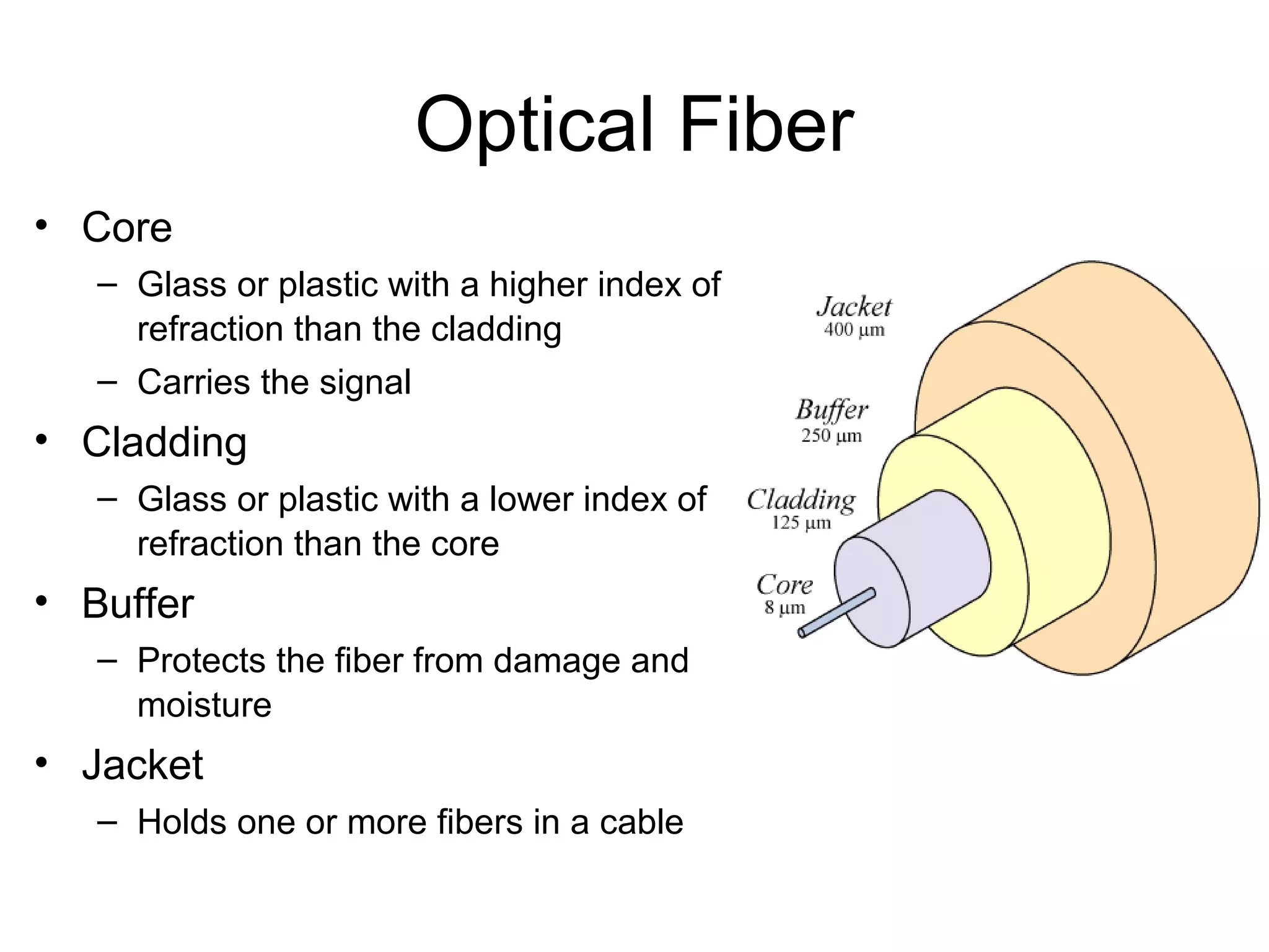
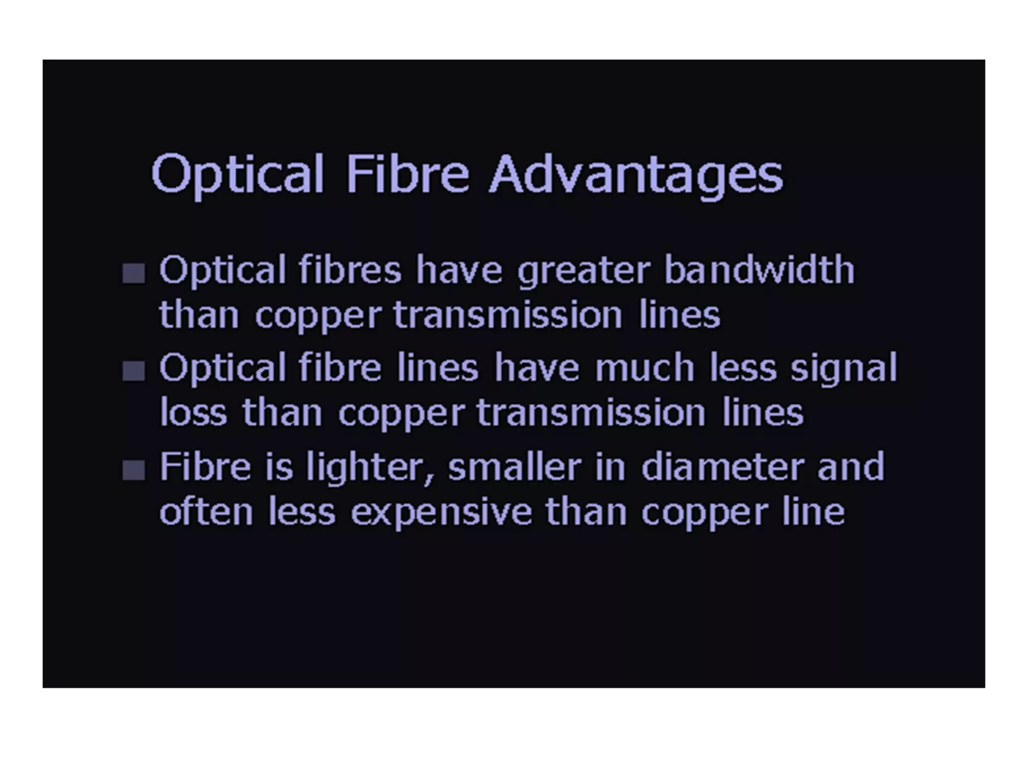
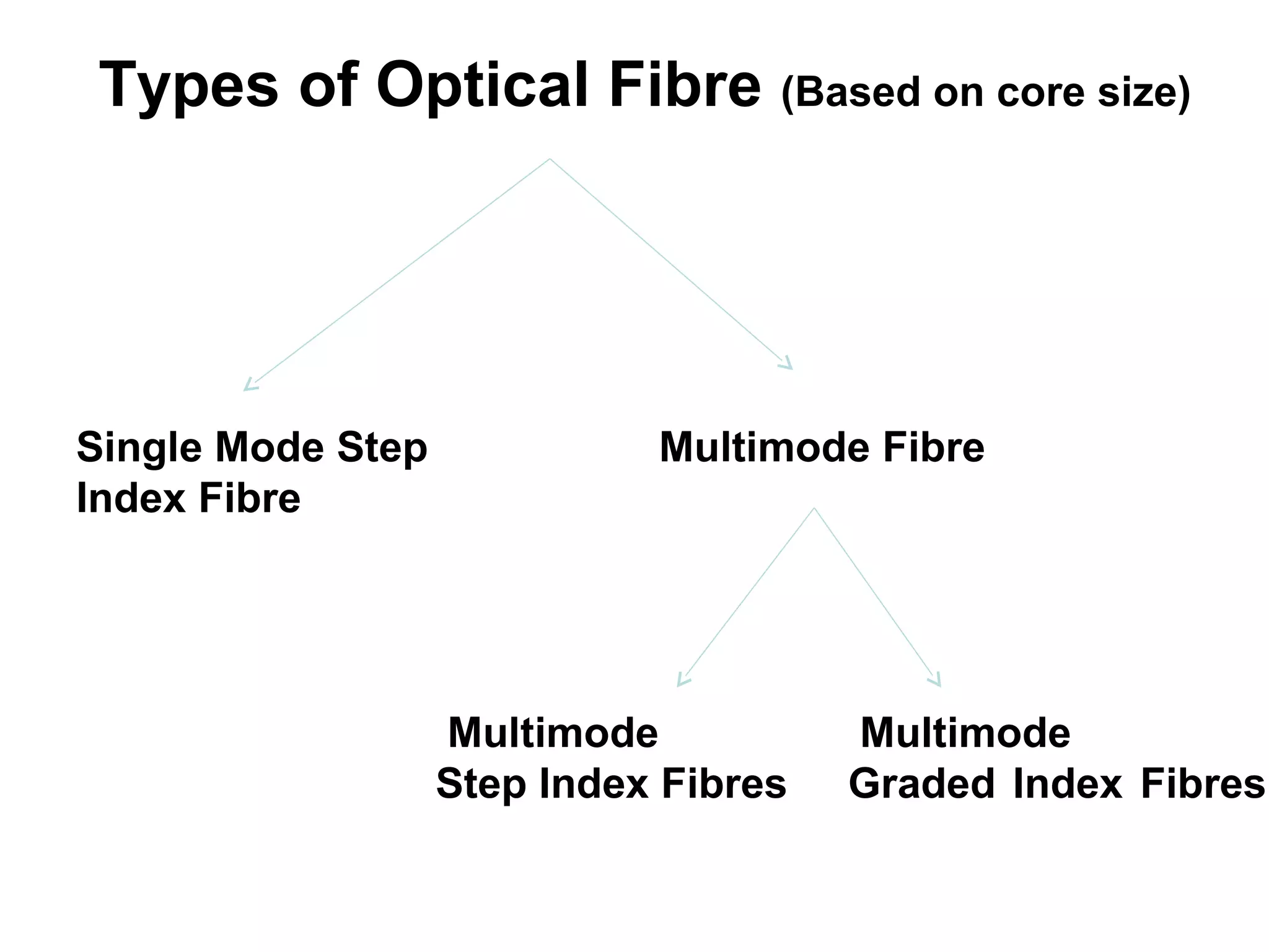
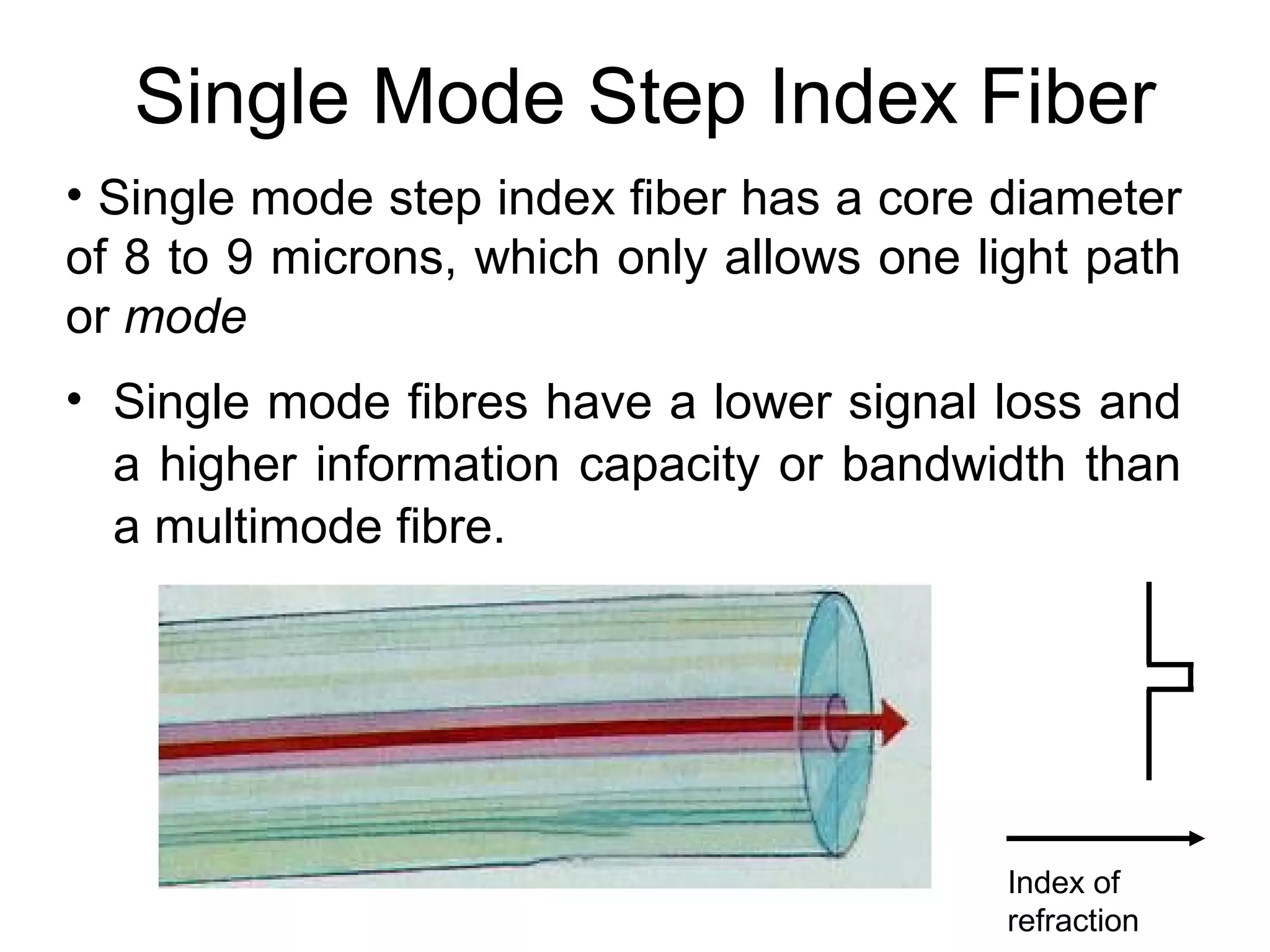
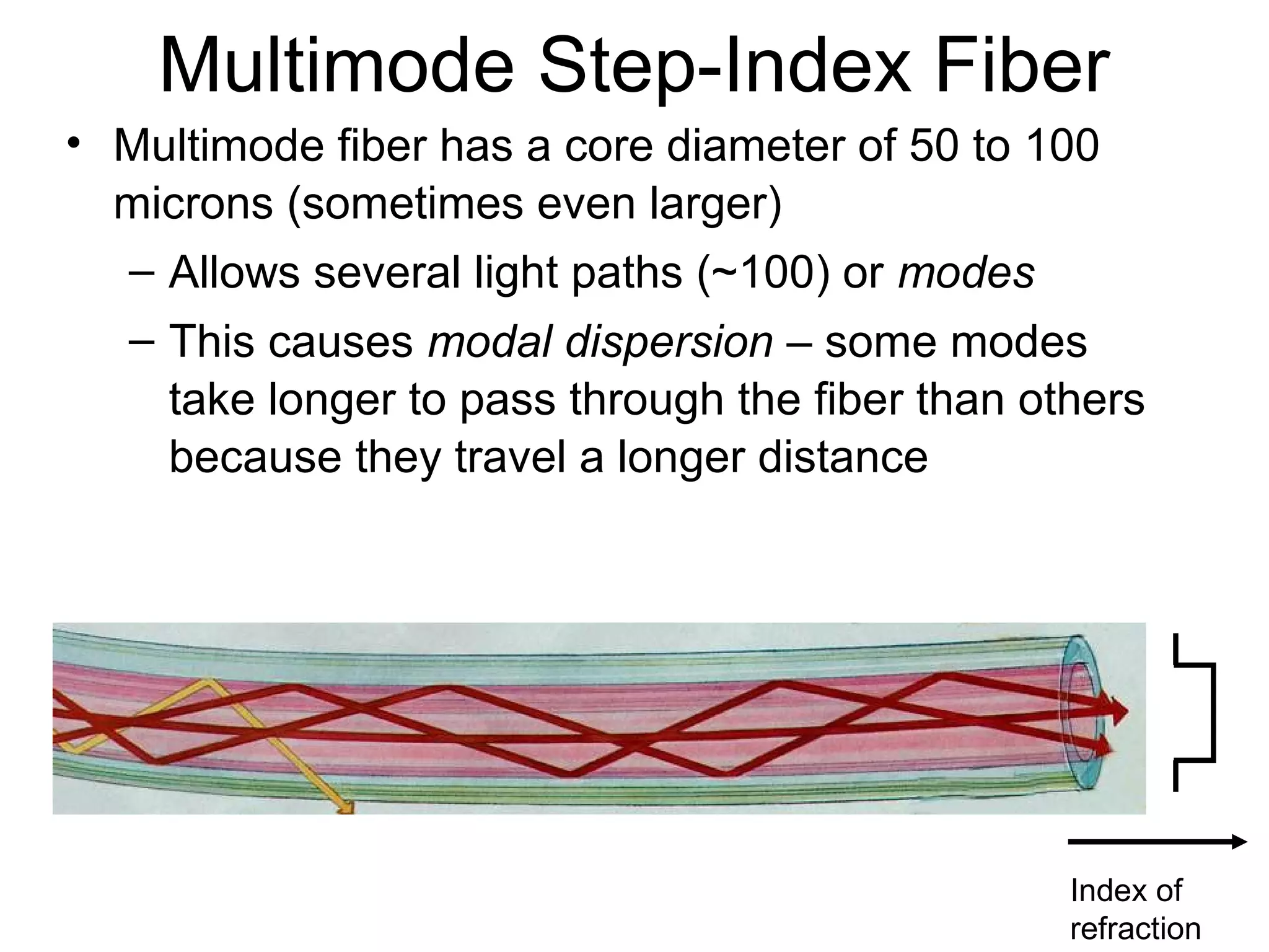
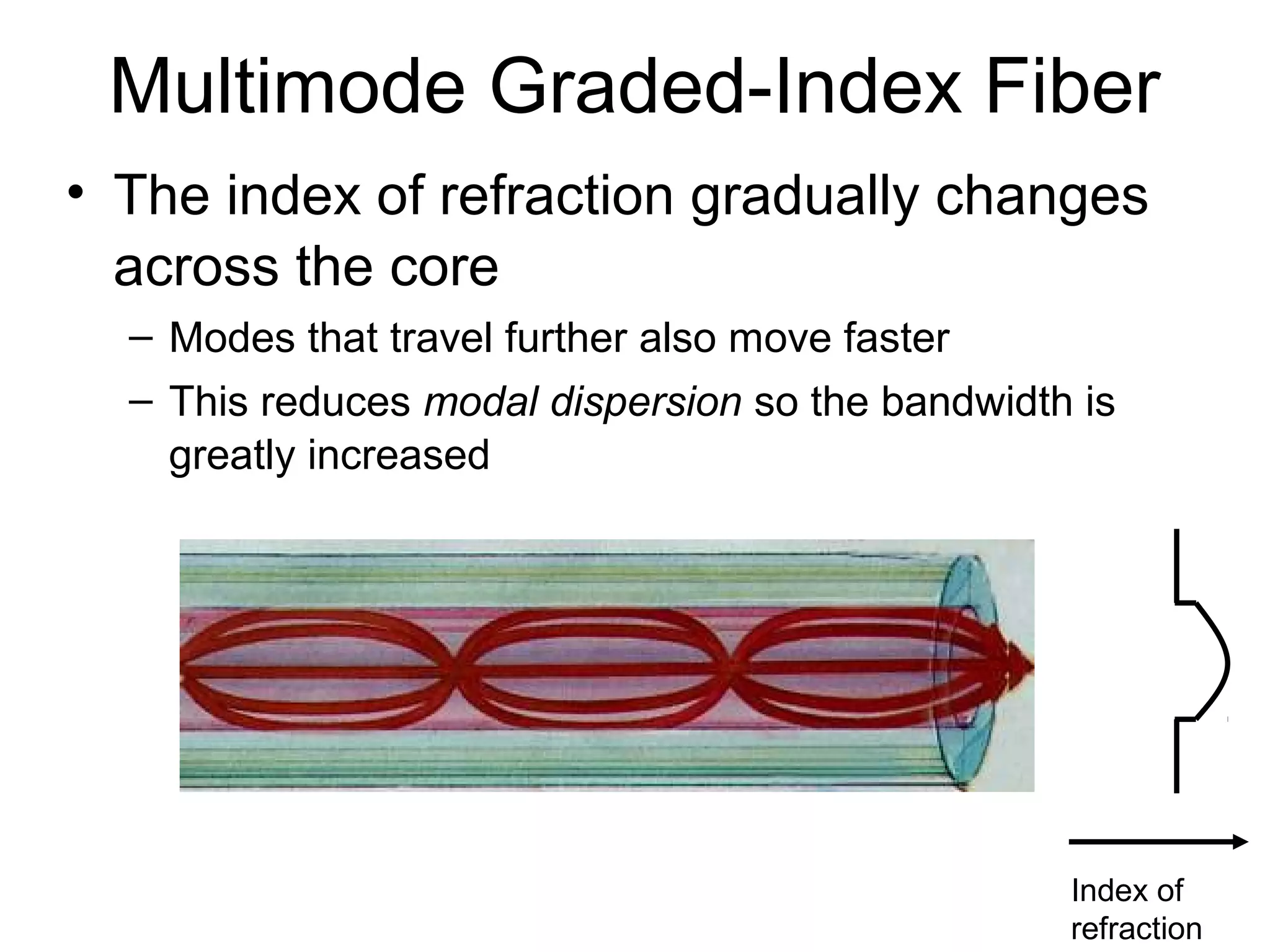
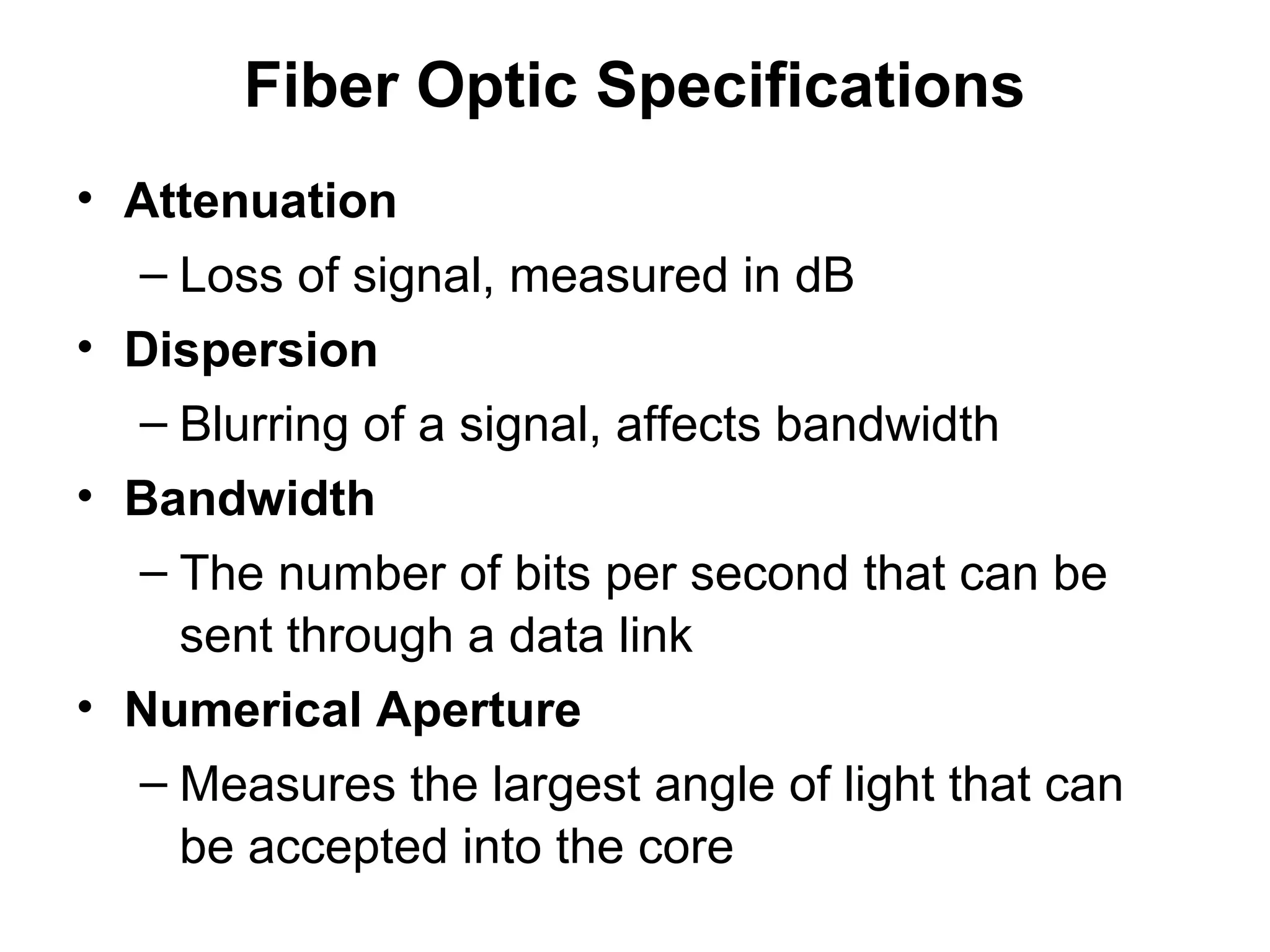
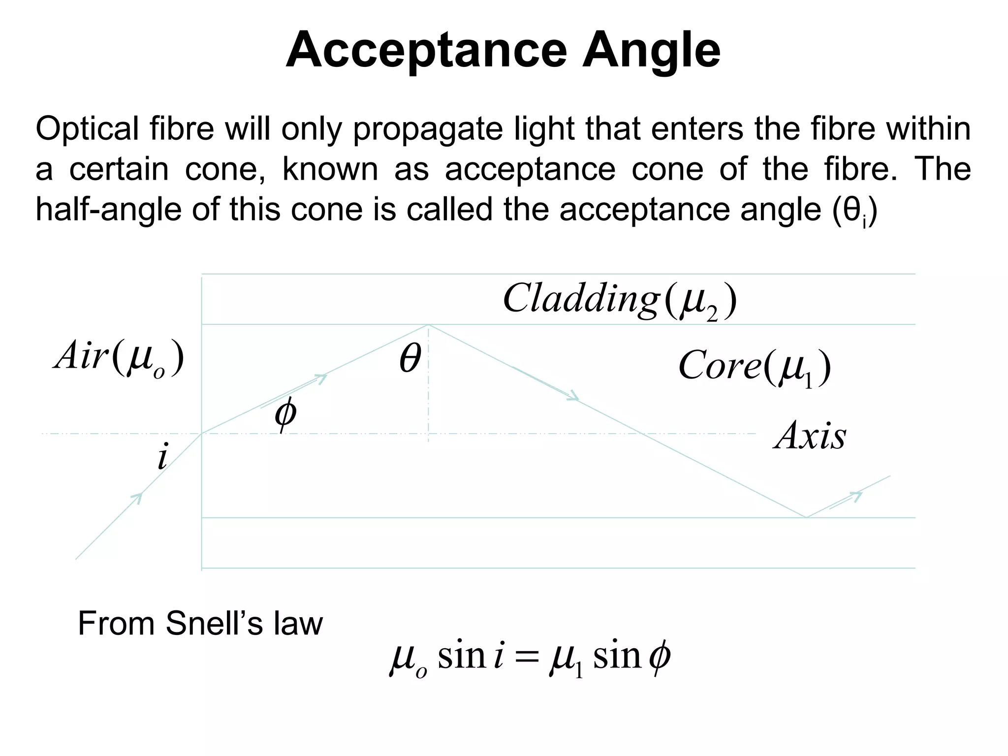
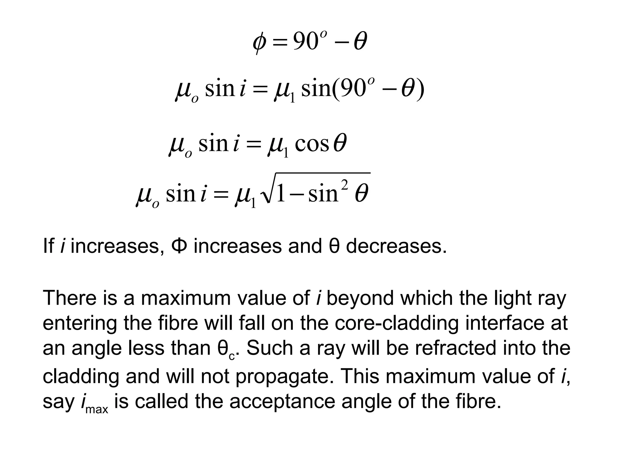
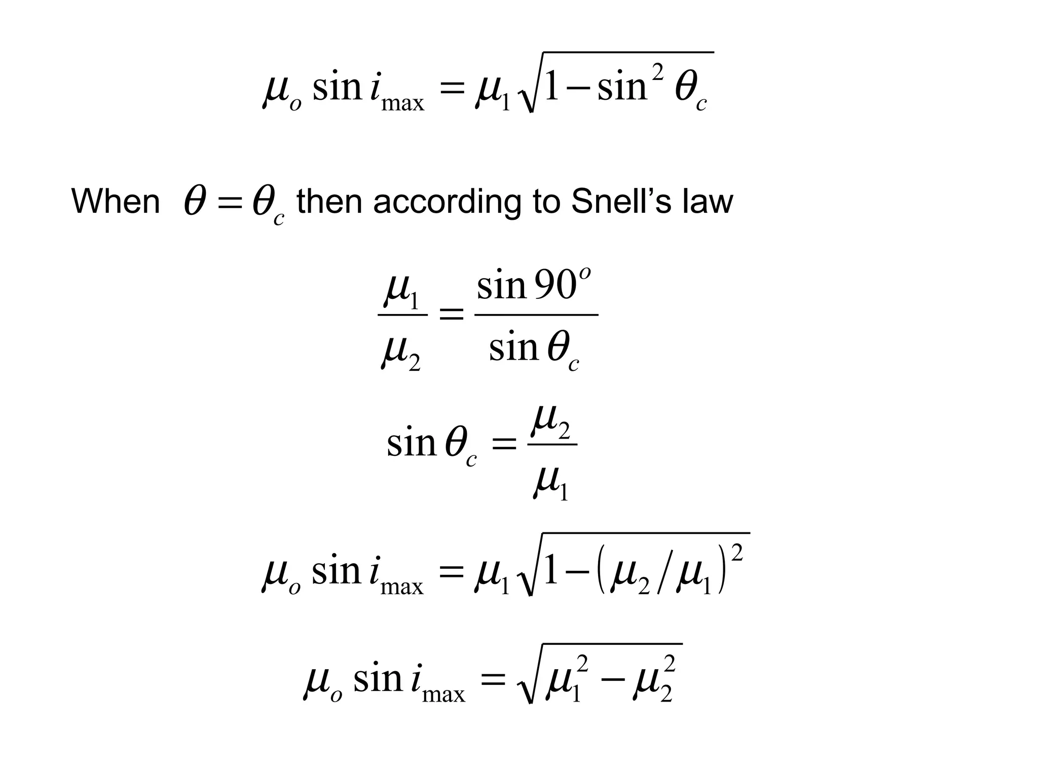
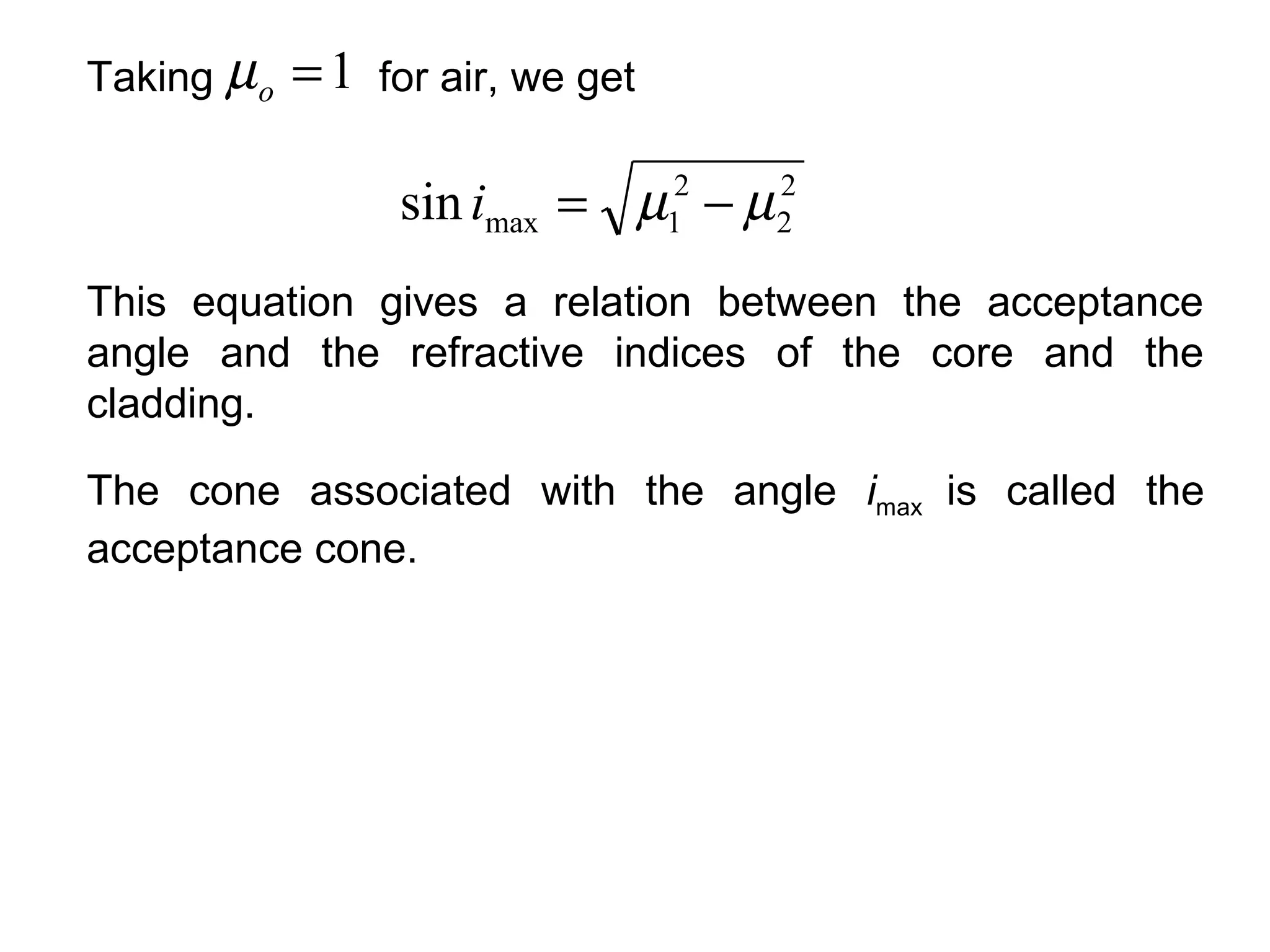
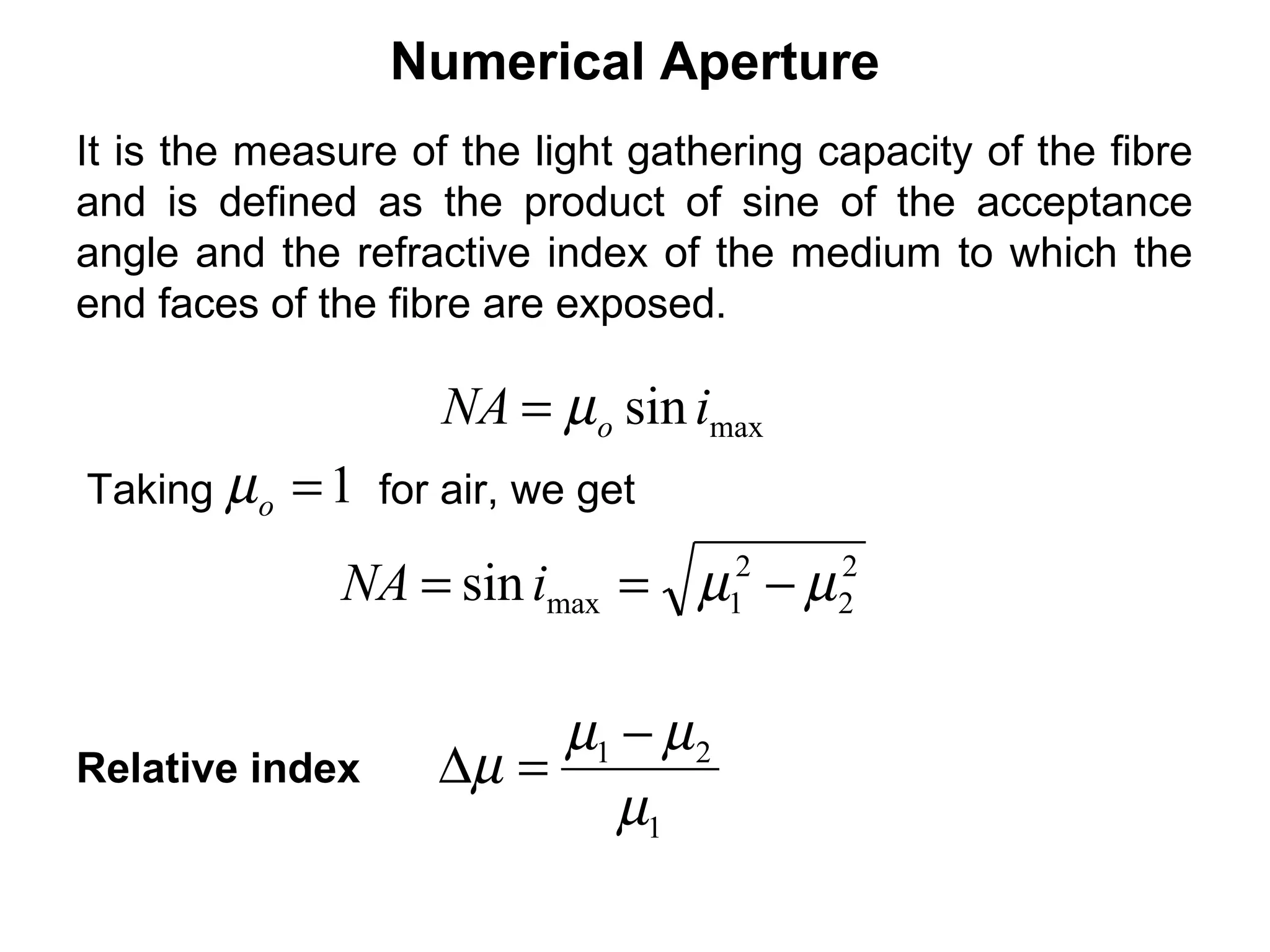
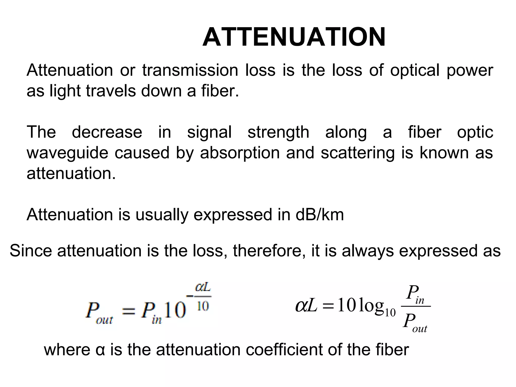
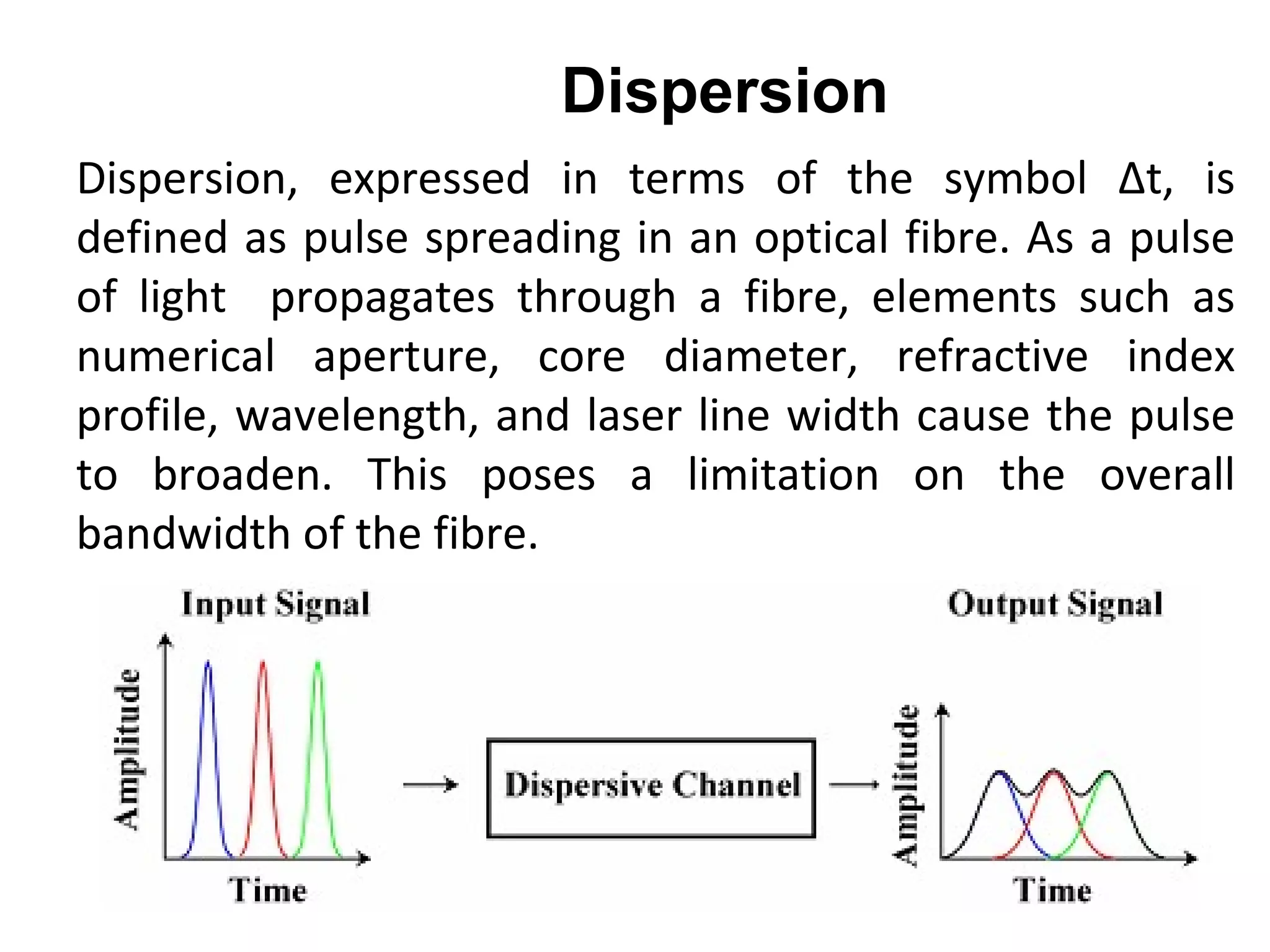
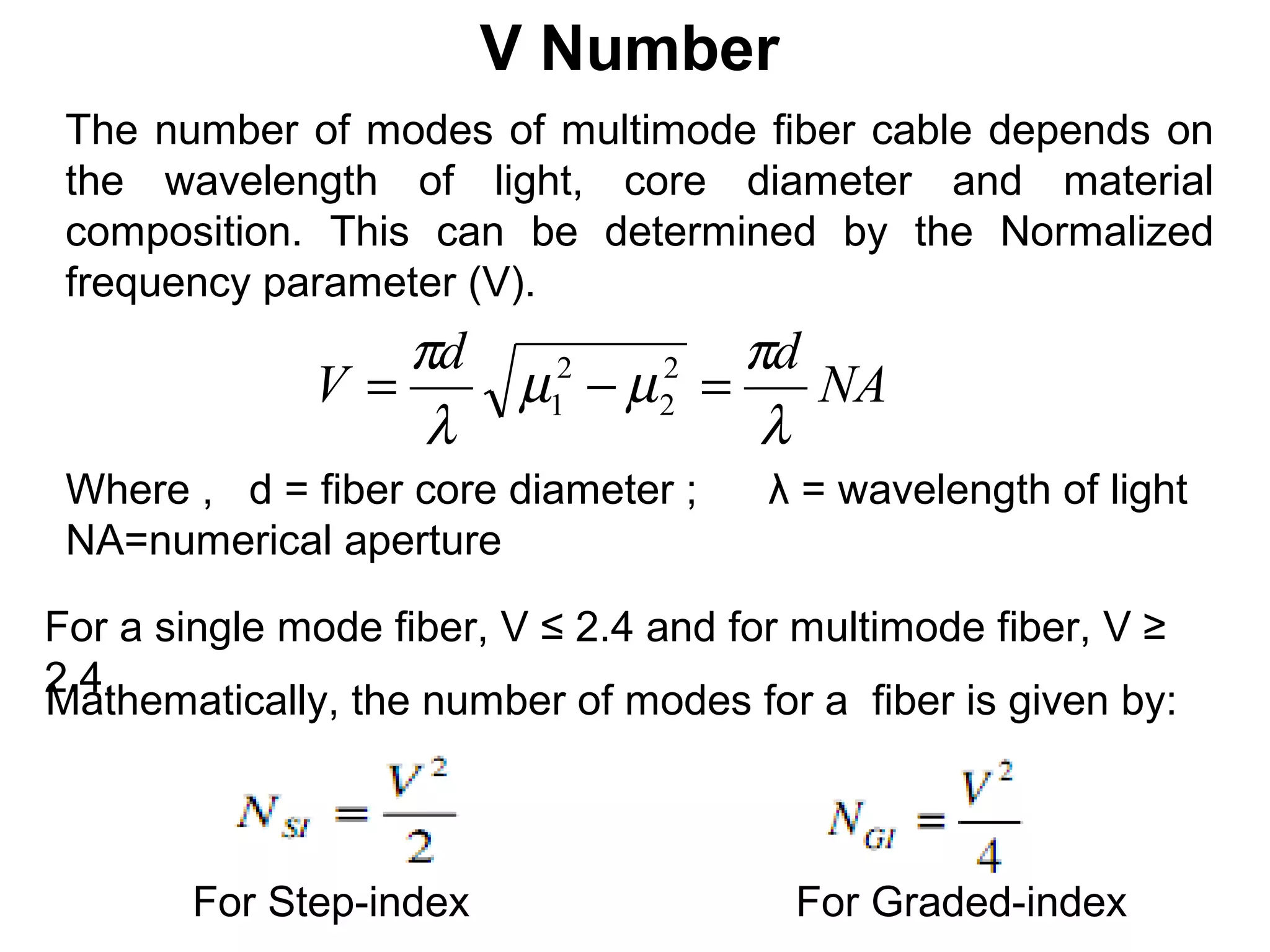

The document discusses optical fibers, which transmit light through the principle of total internal reflection. It describes the core, cladding, buffer, and jacket layers of optical fibers and compares single mode, multimode step index, and multimode graded index fibers. Key advantages of optical fibers include potential low cost using sand-based glass, enormous bandwidth, and high signal security. Fiber specifications like attenuation, dispersion, bandwidth, and numerical aperture are also outlined.