SlideShare a Scribd company logo
6/18/2014
1
OPTICAL FIBER
1
Basic principle Total Internal Reflection in Fiber
2
An optical fiber (or fibre) is a glass or plastic fiber that
carries light along its length.
Light is kept in the "core" of the optical fiber by total
internal reflection.
What Makes The Light Stay in Fiber
• Refraction
– The light waves spread out along its beam.
– Speed of light depend on the material used called
refractive index.
– Speed of light in the material = speed of light in the free
space/refractive index
– Lower refractive index  higher speed
3
The Light is Refracted
Lower Refractive index Region
4
This end travels
further than the
other hand
Higher Refractive index Region
Refraction
• When a light ray encounters a boundary separating two
different media, part of the ray is reflected back into the
first medium and the remainder is bent (or refracted) as it
enters the second material. (Light entering an optical fiber
bends in towards the center of the fiber – refraction)
5
Refraction
LED or
LASER
Source
Reflection
• Light inside an optical fiber bounces off the
cladding - reflection
6
Reflection
LED or
LASER
Source
6/18/2014
2
7
Critical Angle
• If light inside an optical fiber strikes the cladding too steeply, the
light refracts into the cladding - determined by the critical angle.
(There will come a time when, eventually, the angle of
refraction reaches 90o and the light is refracted along the
boundary between the two materials. The angle of incidence
which results in this effect is called the critical angle).
8
Critical Angle
n1Sin X=n2Sin90o
Angle of Incidence
• Also incident angle
• Measured from perpendicular
• Exercise: Mark two more incident angles
9
Incident Angles
Angle of Reflection
• Also reflection angle
• Measured from perpendicular
• Exercise: Mark the other reflection angle
10
Reflection Angle
Reflection
Thus light is perfectly reflected at an interface between
two materials of different refractive index if:
– The light is incident on the interface from the
side of higher refractive index.
– The angle θ is greater than a specific value
called the “critical angle”.
11
Angle of Refraction
• Also refraction angle
• Measured from perpendicular
• Exercise: Mark the other refraction angle
12
Refraction Angle
6/18/2014
3
Angle Summary
• Three important angles
• The reflection angle always equals the incident
angle
13
Refraction Angle
Reflection Angle
Incident Angles
Refractive Index
• n = c/v
– c = velocity of light in a vacuum
– v = velocity of light in a specific medium
• light bends as it passes from one medium to
another with a different index of refraction
– air, n is about 1
– glass, n is about 1.4
14
Light bends in towards normal -
lower n to higher n
Light bends
away from
normal - higher
n to lower n
Snell’s Law
• The amount light is bent by refraction is given by Snell’s
Law:
n1sin 1 = n2sin 2
• Light is always refracted into a fiber (although there will be
a certain amount of Fresnel reflection)
• Light can either bounce off the cladding (TIR) or refract into
the cladding
15
Snell’s Law
16
Normal
Incidence
Angle( 1)
Refraction
Angle( 2)
Lower Refractive index(n2)
Higher Refractive index(n1)Ray of light
Critical Angle Calculation
• The angle of incidence that produces an angle of refraction of 90° is the
critical angle
– n1sin(qc) = n2sin(90°)
– n1sin(qc) = n2
– qc = sin-1(n2 /n1)
• Light at incident angles
greater than the critical
angle will reflect back
into the core
17
Critical Angle, c
n1 = Refractive index of the core
n2 = Refractive index of the cladding
OPTICAL FIBER CONSTRUCTION
18
Core – thin glass center of the fiber where light travels.
Cladding – outer optical material surrounding the core
Buffer Coating – plastic coating that protect the fiber.
6/18/2014
4
OPTICAL FIBER
• The core, and the lower-refractive-index cladding, are
typically made of high-quality silica glass, though they
can both be made of plastic as well.
19
NA & ACCEPTANCE ANGLE DERIVATION
• In optics, the numerical aperture (NA) of an optical
system is a dimensionless number that characterizes
the range of angles over which the system can accept
or emit light.”
• optical fiber will only propagate light that enters the
fiber within a certain cone, known as the acceptance
cone of the fiber. The half-angle of this cone is called
the acceptance angle, θmax.
20
21
When a light ray is incident from a medium of refractive
index n to the core of index n1, Snell's law at medium-core
interface gives
• Substituting for sin θr in Snell's law we get:
By squaring both sides
Thus,
22
• from where the formula given above follows.
• NUMERICAL APERATURE IS
• ACCEPTANCE ANGLE
• θmax =
23
Definition:-
• Acceptance angle:-
• Acceptance angle is defined as the maximum angle of
incidence at the interface of air medium and core medium
for which the light ray enters into the core and travels along
the interface of core and cladding.
• Acceptance Cone:-
• There is an imaginary cone of acceptance with an angle
.The light that enters the fiber at angles within the
acceptance cone are guided down the fiber core
• Numerical aperture:-
• Numerical aperture is defined as the light gathering
capacity of an optical fiber and it is directly proportional to
the acceptance angle.
24
6/18/2014
5
• Three common type of fiber in terms of the material
used:
• Glass core with glass cladding –all glass or silica
fiber
• Glass core with plastic cladding –plastic
cladded/coated silica (PCS)
• Plastic core with plastic cladding – all plastic or
polymer fiber
25
Classification of Optical Fiber Plastic and Silica Fibers
26
BASED ON MODE OF PROPAGATION
• Two main categories of optical fiber used in fiber
optic communications are
• multi-mode optical fiber
• single-mode optical fiber.
27
 Single-mode fiber
 Carries light pulses along single path
 Multimode fiber
 Many pulses of light generated by LED travel at different
angles 28
Based on the index profile
29
The boundary between
the core and cladding
may either be abrupt,
in step-index fiber, or
gradual, in graded-
index fiber
Step Index Fibers
• A step-index fiber has a central core with a uniform
refractive index. An outside cladding that also has a
uniform refractive index surrounds the core;
• however, the refractive index of the cladding is less than
that of the central core.
The refractive index profile may be defined as
n(r) = n1 r < a (core)
n2 r ≥ a (cladding)
30
6/18/2014
6
GRADED-INDEX
• In graded-index fiber, the index of refraction in the
core decreases continuously between the axis and the
cladding.
• This causes light rays to bend smoothly as they
approach the cladding, rather than reflecting abruptly
from the core-cladding boundary.
31
32
Figure.2.6
(a)
(b)
• multimode step-index fiber
– the reflective walls of the fiber move the light pulses to
the receiver
• multimode graded-index fiber
– acts to refract the light toward the center of the fiber by
variations in the density
• single mode fiber
– the light is guided down the center of an extremely
narrow core
33
Figure 2.10 Two types of fiber: (Top) step index fiber; (Bottom) Graded
index fiber 34
Attenuation
• Definition: a loss of signal strength in a lightwave, electrical
or radio signal usually related to the distance the signal
must travel.
Attenuation is caused by:
• Absorption
• Scattering
• Radiative loss
35
Losses
• Losses in optical fiber result from attenuation in the
material itself and from scattering, which causes some
light to strike the cladding at less than the critical angle
• Bending the optical fiber too sharply can also cause
losses by causing some of the light to meet the cladding
at less than the critical angle
• Losses vary greatly depending upon the type of fiber
– Plastic fiber may have losses of several hundred dB
per kilometer
– Graded-index multimode glass fiber has a loss of
about 2–4 dB
per kilometer
– Single-mode fiber has a loss of 0.4 dB/km or less
36
6/18/2014
7
Macrobending Loss:
• The curvature of the bend is much larger than fiber
diameter. Lightwave suffers sever loss due to radiation of
the evanescent field in the cladding region. As the radius of
the curvature decreases, the loss increases exponentially
until it reaches at a certain critical radius. For any radius a
bit smaller than this point, the losses suddenly becomes
extremely large. Higher order modes radiate away faster
than lower order modes.
37
Micro bending Loss
• Micro bending Loss:
microscopic bends of
the fiber axis that can
arise when the fibers are
incorporated into cables.
The power is dissipated
through the micro
bended fiber, because of
the repetitive coupling
of energy between
guided modes & the
leaky or radiation modes
in the fiber. 38
Dispersion
• The phenomenon in an optical fibre whereby light photons
arrive at a distant point in different phase than they
entered the fibre.
• Dispersion causes receive signal distortion that ultimately
limits the bandwidth and usable length of the fiBer cable
The two main causes of dispersion are:
 Material (Chromatic) dispersion
Waveguide dispersion
Intermodal delay (in multimode fibres)
39
• Dispersion in fiber optics results from the fact that in
multimode propagation, the signal travels faster in some
modes than it would in others
• Single-mode fibers are relatively free from dispersion
except for intramodal dispersion
• Graded-index fibers reduce dispersion by taking advantage
of higher-order modes
• One form of intramodal dispersion is called material
dispersion because it depends upon the material of the
core
• Another form of dispersion is called waveguide dispersion
• Dispersion increases with the bandwidth of the light source
40
Advantages of Optical Fibre
• Thinner
• Less Expensive
• Higher Carrying
Capacity
• Less Signal
Degradation& Digital
Signals
• Light Signals
• Non-Flammable
• Light Weight
41
Advantages of fiber optics
42
 Much Higher Bandwidth (Gbps) - Thousands of
channels can be multiplexed together over one strand
of fiber
 Immunity to Noise - Immune to electromagnetic
interference (EMI).
 Safety - Doesn’t transmit electrical signals, making it
safe in environments like a gas pipeline.
 High Security - Impossible to “tap into.”
6/18/2014
8
Advantages of fiber optics
 Less Loss - Repeaters can be spaced 75 miles apart
(fibers can be made to have only 0.2 dB/km of
attenuation)
 Reliability - More resilient than copper in extreme
environmental conditions.
 Size - Lighter and more compact than copper.
 Flexibility - Unlike impure, brittle glass, fiber is
physically very flexible.
43
Fiber Optic Advantages
• greater capacity (bandwidth up
to 2 Gbps, or more)
• smaller size and lighter weight
• lower attenuation
• immunity to environmental
interference
• highly secure due to tap
difficulty and lack of signal
radiation
44
Disadvantages of fiber optics
• Disadvantages include
the cost of interfacing
equipment necessary to
convert electrical
signals to optical
signals. (optical
transmitters, receivers)
Splicing fiber optic cable
is also more difficult.
45
Areas of Application
• Telecommunications
• Local Area Networks
• Cable TV
• CCTV
• Optical Fiber Sensors
46
Formula Summary
• Index of Refraction
Snell’s Law
Critical Angle
Acceptance Angle
Numerical Aperture 47
v
c
n
2211
sinsin nn
1
21
sin
n
n
c
2
2
2
1
1
sin nn
2
2
2
1
sin nnNA
STUDENTS YOU CAN ALSO REFER IT……
48
http://hank.uoregon.edu/experiments/Dispersion-in-
Optical-Fiber/Unit_1.6%20(2).pdf
http://www1.ceit.es/asignaturas/comuopticas/pdf/chapter
4.pdf
http://course.ee.ust.hk/elec342/notes/Lecture%206_attenu
ation%20and%20dispersion.pdf
1 Engineering Physics by H Aruldhas, PHI India
2 Engineering Physics by B K Pandey , S. Chaturvedi, Cengage
Learning
3 Resnick, Halliday and Krane, Physics part I and II, 5th
Edition John Wiely
4 Engineering Physics by S.CHAND
5 Engineering Physics by G VIJIYAKUMARI
6/18/2014
1
Dielectrics are the materials having electric dipole
moment permanently.
Dipole: A dipole is an entity in which equal positive
and negative charges are separated by a small
distance..
DIPOLE moment (µEle ):The product of magnitude of
either of the charges and separation distance b/w
them is called Dipole moment.
µe = q . x  coulmb.m
All dielectrics are electrical insulators and they are
mainly used to store electrical energy.
Ex: Mica, glass, plastic, water & polar
molecules…
X
q -q
Introduction
+
Electric field
Dielectric atom
+
+
+
+
+
+
+
+
_
_
_
_
_
_
_
__
dipole
The relative permittivity(εr) is often known as
dielectric const. of medium it can given by,
εr=ε/ε0
Dielectric constant is ratio of permittivity of medium
to permittivity of free space.
The value of capacitance of capacitor is given by,
C0=εrε0A/d
By this eqn we can say that high εr increases capacity
of capacitor.
Polar and Nonpolarized Molecules
Non-polar Molecules : The Dielectric material in which
there is no permanent dipole existence in absence of an
external field is …..
O=O N N Cl-Cl F-F Br-Br I-I
2 – Compoundsmade of molecules which are symmetrically shaped
carbon tetra fluoride CF4
propane
C3H8
methane CH4
carbon tetra fluoride CCl4,
carbon dioxide
O=C=O
Polar Molecules The Dielectric material in which there is
permanent dipole existence even in absence of an
external field is …..
HCl
hydrogen chloride
carbon monoxide
C O
2 – molecules with O, N, or OH at one end – asymmetrical
e.g.; CH2Cl2,CH3Cl
water
H2O
unbounded electron pairs
bend the molecule
ammonia
nitrogen trihydride
NH3
alcohols
methanol
CH3OH
6/18/2014
2
Identify each of the following molecules as
1) polar or 2) nonpolarized. Explain.
A. PBr3
B. HBr
C. Br2
D. SiBr4
7
Identify each of the following molecules as
1) polar or 2) nonpolarized. Explain.
A. PBr3 1) pyramidal; dipoles don’t cancel; polar
B. HBr 1) linear; one polar bond (dipole); polar
C. Br2 2) linear; nonpolarized bond; nonpolarized
D. SiBr4 2) tetrahedral; dipoles cancel; no polar
8
As shown in fig. when an electric field is
applied to dielectric material their
negative & positive charges tend to
align in equilibrium position.
 They produce electric dipole inside the material.
 This phenomenon is known as Polarization.
 It can be represented by,
P=polarization
μ= dipole moment
V=Volume
 Unit=Cm-2
 Now dipole moment depends upon applied electric field.
 α polarizability of material.
P
V


E
P E
P E



 

 
+
+
+
+
+
+
+
+
-
-
-
-
-
-
-
-
E0
-
-
-
-
-
-
-
-
-
-
-
-
-
-
-
-
-
-
-
-
-
-
++
--
++
--
++
--
++
--
++
--
++
--
++
--
++
--
++
--
++
--
++
--
+
q
-
q
-
q
+
q
-
q
+
q
+
+
+
+
+
+
+
+
+
+
+
+
+
+
+
+
+
+
+
+
+
+
E0
 In absence of
dielectric
 In presence of
dielectric
0
0
0
0
0
.E ds q
q
E A
q
E
A






 0
0 0
0 0
. '
'
'
E ds q q
q q
EA
q q
E
A A

 
 
 
 
 

6/18/2014
3
 V=Ed
 So
 Now
0 0
d
E V
k
E V
 
0
0
0 0
0 0 0
'
'
,
1
, ' (1 )
E q
E
k kA
q q
E
A A
q q q
So
kA A A
then q q
k

 
  
 
 
 
 
0
0
So, . '
1
(1 )
q
.
E ds q q
q q
k
k
k E ds q


 
  




This relation true is for parallel plate capacitor
Which is Gauss’s law for dielectrics
 The resultant dielectric field is given by,
Where,
E=Electric field
D=Flux Density or
Displacement vector
P=Polarization
0 0
0 0
0
0
'
'
,
,
, D
p
q q
E
A A
q
now P
A
q P
E
A
q
E P
A
q
now D
A
So E P
 

 


 
 
  
  

 
Electric susceptibility:
The polarization vector P is proportional
to the total electric flux density and
direction of electric field.
Therefore the polarization vector can be
written
0
0
0
0
( 1)
1
e
e
r
e r
P E
P
E
E
E
 


 

 




 
 Displacement vector,
0
0
0
r 0 0
0
D E P
Now,P=
( - ) E P
(or) ( . - ) E P
( 1) . P
W here,( 1)
r
r
E
E


 
  
 
 
 
 

 
 
1. Electron polarization
2. Ionic polarization
3. Orientation polarization
4. Space charge polarization
6/18/2014
4
 When no external field is applied nucleus of
atom is like in fig. (a)
 When external field is applied, displacement
in opposite direction is observed between
nucleus & electrons due to this dipole
moment is induced.
 This type of polarization is called Electronic
polarization.
 Ex. Germanium, Silicon, Diamond etc…
19
+
-
+
-
-
Electric Field(a) (b)
 Some materials like ionic crystal does not
possess permanent dipole moment.
 Fig. (a) shows natural arrangement of ionic
crystal. When Ele. Field is applied on this type
of material displacement of ions is observed.
 Due to an external electric field a positive &
negative ion displaces in the direction
opposite to each other due to which distance
between them is reduced & ionic polarization
is generated.
 Ionic polarization is observed in materials like
NaCl, KBr, KCl etc…
 Let us consider simple example of NaCl
crystal.
 As shown in fig. when crystal is placed in an
external electric field Na+ ion displaces in one
direction & Cl- ion goes in opposite direction.
 Some molecules like H2O, HCl having permanent dipole
moment p0.
 In the absence of a field, individual dipoles are
arranged in random way, so net average dipole
moment in a unit volume is zero as shown in fig. (b).
 A dipole such as HCl placed in a field experiences a
torque that tries to rotate it to align p0 with the field E.
 In the presence of an applied field, the
dipoles try to rotate to align parallel to each
other in direction of electric field fig (d).
 This type of polarization is Orientation
polarization.
 This type of polarization occurs only in polar
substances like H2O, CH3Cl when they are
placed in external field.
 A crystal with equal number of mobile positive ions
and fixed negative ions.
 In the absence of a field, there is no net separation
between all the positive charges and all the
negative charges.
6/18/2014
5
 In the presence of an applied field, the
mobile positive ions migrate toward the
negative charges and positive charges in the
dielectric.
 The dielectric therefore exhibits Space charge
or interfacial polarization.
.
?
.
.
dW F dr
F
dW qE dr
dW E dp
p p
P
lA V




 
0
0
0
2
0
2
0
( 1) .
. .( 1) .
. .( 1) .
1
( 1) E
2
1
( 1) E
2
?
r
r
r
r
r
p PV
dW EVdP
P E
dW E V dE
dW E V dE
W V
W
V
U
 
 
 
 
 


 
 
 
 
 

 
References:
Engineering physics By Dr. M N Avadhnulu, S Chand
publication
Engineering physics by K Rajgopalan
http://web.mit.edu/viz/EM/visualizations/coursenote
s/modules/guide05.pdf
6/18/2014
1
Band Theory of Solid
 Objectives
• Effective Mass of electron
• Concept of Holes
• Energy Band Structure of Solids:
 Conductors, Insulators and Semiconductors
• Semiconductors
 Intrinsic and Extrinsic Semiconductors
• Type of diodes
 Simple Diode
 Zener Diode
 Effective Mass of electron
An electron moving in the solid under the
influence of the crystal potential is subjected to an
electric field.
We expect an external field to accelerate the
electron, increasing E and k and change the
electron’s state.
dt
dx
dx
dV
e
dt
dV
e
dt
d
eV
and
dk
d
gv

1
gv
dx
dV
e
dt
dk
dk
d
dx
dV
ek
dt
d
gv
dx
dV
e
dt
dk
gv


eEk
dt
d

dt
dk
dk
d
dk
d
dk
d
dt
d
dt
dv
a
g

11
k
dt
d
dk
d
dt
dk
dk
d

 2
2
22
2
11
eE = F
e
1
m
 Concept of Holes
Consider a semiconductor with a small number of
electrons excited from the valence band into the
conduction band.
If an electric field is applied,
• the conduction band electrons will participate
in the electrical current
• the valence band electrons can “move into”
the empty states, and thus can also contribute
to the current.
6/18/2014
2
 Concept of Holes
If we describe such changes via “movement” of the
“empty” states – the picture will be significantly
simplified. This “empty space” is called a Hole.
“Deficiency” of negative charge can be treated as a
positive charge.
Holes act as charge carriers in the sense that
electrons from nearby sites can “move” into the
hole.
Holes are usually heavier than electrons since they
depict collective behavior of many electrons.
Electrical current for holes and electrons in the same
direction
• To understand hole motion, one requires another
view of the holes, which represent them as
electrons with negative effective mass m*.
• For example the movement of the hole think of a
row of chairs occupied by people with one chair
empty, and to move all people rise all together
and move in one direction, so the empty spot
moves in the same direction
 Energy Band Structure of Solids
Conductor, Semiconductor and Insulator
In isolated atoms the electrons are arranged in
energy levels.
 Energy Band in Solid
The following are the important energy
band in solids:
 Valence band
 Conduction band
 Forbidden energy gap or Forbidden band
Valance band
The band of energy occupied by the valance
electrons is called valence band. The electrons in the
outermost orbit of an atom are known as valance
electrons. This band may be completely or partial filled.
Electron can be move from one valance band to
the conduction band by the application of external
energy.
6/18/2014
3
 Conduction band
The band of energy occupied by the conduction
electrons is called conduction band. This is the
uppermost band and all electrons in the conduction
band are free electrons.
The conduction band is empty for insulator and
partially filled for conductors.
 Forbidden Energy Gap or Forbidden band
The gap between the valance band and
conduction band on energy level diagram known as
forbidden band or energy gap.
Electron are never found in the gap. Electrons
may jump from back and forth from the bottom of
valance band to the top of the conduction band. But
they never come to rest in the forbidden band.
 According to the classical free electron theory,
materials are classified in to three types:
 Conductors
 Semiconductors
 Insulators
Conductors
There is no forbidden gap and the conduction band
and valence band are overlapping each other between and
hence electrons are free to move about. Examples are Ag,
Cu, Fe, Al, Pb ….
 Conductor are highly electrical conductivity.
 So, in general electrical resistivity of conductor is very low
and it is of the order of 10-6 Ω cm.
 Due to the absence of the forbidden gap, there is no
structure for holes.
 The total current in conductor is simply a flow of
electrons.
 For conductors, the energy gap is of the order of 0.01 eV.
Semiconductors
Semiconductors are materials whose electrical
resistivity lies between insulator and conductor. Examples
are silicon (Si), germanium (Ge) ….
 The resistivity of semiconductors lie between 10-4 Ω cm to
103 Ω cm at room temperature.
 At low temperature, the valence band is all most full and
conduction band is almost empty. The forbidden gap is
very small equal to 1 eV.
 Semiconductor behaves like an insulator at low
temperature. The most commonly used semiconductor is
silicon and its band gap is 1.21 eV and germanium band
gap is 0.785 eV.
When a conductor is heated its resistance
increases; The atoms vibrate more and the
electrons find it more difficult to move through
the conductor but, in a semiconductor the
resistance decreases with an increase in
temperature. Electrons can be excited up to the
conduction band and Conductivity increases.
6/18/2014
4
Insulators
In insulator, the valence band is full but the
conduction band is totally empty. So, free electrons from
conduction band is not available.
 In insulator the energy gap between the valence and
conduction band is very large and its approximately
equal to 5 eV or more.
 Hence electrons cannot jump from valence band to the
conduction band. So, a very high energy is required to
push the electrons to the conduction band.
 The electrical conductivity is extremely small.
 The resistivity of insulator lie between 103 to 1017 Ωm, at
the room temperature
 Examples are plastics, paper …..
 Types of semiconductors
Semiconductors
Intrinsic Semiconductor Extrinsic Semiconductor
p - type n - type
 Intrinsic Semiconductor
 The intrinsic semiconductor are pure semiconductor materials.
 These semiconductors posses poor conductivity.
 The elemental and compound semiconductor can be intrinsic
type.
 The energy gap in semiconductor is very small.
 So even at the room temperature, some of electrons from
valance band can jump to the conduction band by thermal
energy.
 The jump of electron in conduction band adds one conduction
electron in conduction band and creates a hole in the valence
band. The process is called as “generation of an electron–hole
pair”.
 In pure semiconductor the no. of electrons in conduction band
and holes in holes in valence bands are equal.
 Extrinsic Semiconductor
 Extrinsic semiconductor is an impure semiconductor
formed from an intrinsic semiconductor by adding a small
quantity of impurity atoms called dopants.
 The process of adding impurities to the semiconductor
crystal is known as doping.
 This added impurity is very small of the order of one atom
per million atoms of pure semiconductor.
 Depending upon the type of impurity added the extrinsic
semiconductors are classified as:
(1) p – type semiconductor
(2) n – type semiconductor
The application of band theory to n-type and p-
type semiconductors shows that extra levels have been added
by the impurities.
In n-type material there are electron energy levels near
the top of the band gap so that they can be easily excited into
the conduction band.
In p-type material, extra holes in the band gap allow
excitation of valence band electrons, leaving mobile holes in the
valence band.
p – type semiconductor
The addition of trivalent impurities such as boron,
aluminum or gallium to an intrinsic semiconductor creates
deficiencies of valence electrons,called "holes". It is typical
to use B2H6 diborane gas to diffuse boron into the silicon
material.
6/18/2014
5
n – type semiconductor
The addition of pentavalent impurities such as
antimony, arsenic or phosphorous contributes free
electrons, greatly increasing the conductivity of the
intrinsic semiconductor. Phosphorous may be added by
diffusion of phosphine gas (PH3).
 Simple Diode (p n- junction Diode)
 The two terminals are called Anode and Cathode.
 At the instant the two materials are “joined”, electrons
and holes near the junction cross over and combine with
each other.
 Holes cross from P-side to N-side and Free electrons cross
from N-side to P-side.
 At P-side of junction, negative ions are formed.
 At N-side of junction, positive ions are formed.
Depletion region is the region having no free
carriers.
Further movement of electrons and holes across
the junction stops due to formation of depletion
region.
Depletion region acts as barrier opposing further
diffusion of charge carriers. So diffusion stops
within no time.
Current through the diode under no-bias
condition is zero.
Positive of battery connected to n-type material
(cathode).
Negative of battery connected to p-type material
(anode).
Reverse bias…..
 Free electrons in n-region are drawn towards positive of
battery, Holes in p-region are drawn towards negative of
battery.
 Depletion region widens, barrier increases for the flow of
majority carriers.
 Majority charge carrier flow reduces to zero.
 Minority charge carriers generated thermally can cross
the junction – results in a current called “reverse
saturation current” Is , Is is in micro or nano amperes or
less. Is does not increase “significantly” with increase in
the reverse bias voltage
Forward bias
 Positive of battery connected to p-type (anode)
 Negative of battery connected to n-type (cathode)
6/18/2014
6
Forward bias…
 Electrons in n-type are forced to recombine with
positive ions near the boundary, similarly holes in p-
type are forced to recombine with negative ions.
 Depletion region width reduces.
 An electron in n-region “sees” a reduced barrier at the
junction and strong attraction for positive potential.
 As forward bias is increased, depletion region narrows
down and finally disappears – leads to exponential rise
in current.
 Forward current is measured in milli amperes
 Zener Diode
A diode which is heavily doped and which
operates in the reverse breakdown region with a
sharp breakdown voltage is called a Zener diode.
This is similar to the normal diode except that
the line (bar) representing the cathode is bent at
both side ends like the letter Z for Zener diode.
In simple diode the doping is light; as a result,
the breakdown voltage is high and not sharp. But if
doping is made heavy, then the depletion layers
becomes very narrow and even the breakdown
voltage gets reduced to a sharp value.
 Working Principle
The reverse breakdown of a Zener diode may
occur either due to Zener effect or avalanche effect.
But the Zener diode is primarily depends on Zener
effect for its working.
 When the electrical field across the junction is
high due to the applied voltage, the Zener
breakdown occurs because of breaking of covalent
bonds and produces a large number of electrons
and holes which constitute a steep rise in the
reverse saturation current (Zener current IZ). This
effect is called as Zener effect.
 Zener current IZ is independent of the applied
voltage and depends only on the external
resistance.
I-V characteristic of a Zener diode
The forward characteristic is simply that of an
ordinary forward biased junction diode. Under the
reverse bias condition, the breakdown of a junction
occurs.
Its depends upon amount of doping. It can be
seen from above figure as the reverse voltage is
increased the reverse current remains negligibly
small up to the knee point (K) of the curve.
6/18/2014
7
 At point K, the effect of breakdown process
beings. The voltage corresponding to the point K
in figure is called the Zener breakdown voltage
or simply Zener voltage (VZ), which is very sharp
compared to a simple p-n junction diode. Beyond
this voltage the reverse current (IZ) increases
sharply to a high value.
 The Zener diode is not immediately burnt just
because it has entered the breakdown region.
 The Zener voltage VZ remains constant even
when Zener current IZ increases greatly.
The maximum value of current is denoted by IZ
max and the minimum current to sustain breakdown
is denoted by IZ min. By two points A and B on the
reverse VI characteristic, the Zener resistance is
given by the relation,
rz = ( Δ VZ / Δ IZ) -----(1)
 Zener diode Applications:
I. Zener diodes are used as a voltage regulator.
II. They are used in shaping circuits as peak
limiters or clippers.
III. They are used as a fixed reference voltage in
transistor biasing and for comparison purpose.
IV. They are used for meter protection against
damage from accidental application of
excessive voltage.
6/18/2014
1
LASER
Light Amplification by Stimulated
Emission of Radiation
 Objectives…
Introduction and understand the principle of
LASER
• Light Amplification by Stimulated Emission of
Radiation
• Absorption
• Spontaneous Emission
• Stimulated Emission
• Population Inversion
• Optical Pumping
 Objectives…
 Characteristics or Properties of Laser Light
• Coherence
• High Intensity
• High directionality
• High monochromaticity
Laser light is highly powerful and it is capable
of propagating over long distances and it is not
easily absorbed by water.
Introduction
• LASER
“Light Amplification by Stimulated Emission
of Radiation”
• MASER (1939 Towner)
“Microwave Amplification by Stimulated
Emission of Radiation”
• Stimulated Emission - Einstein in 1917.
• Ruby Crystal LASER - Maiman, California in 1960.
• He-Ne LASER - Ali Javan in 1961.
• Diode LASER- Hall in 1962.
 Light having following Properties
 Wavelength
 Frequency
 Amplitude
 Phase
 Coherence/Incoherence
 Velocity
 Direction
Absorption
• E1 = Ground state
• E2 = Excited State
• E = hν (Photon Energy)
6/18/2014
2
• According to Bohr’s law atomic system is
characterized by discrete energy level.
• When atoms absorb or release energy it
transit upward or downward.
• Lower level E1 & Excited level E2
• So, h ƒ = E2 – E1
• The rate of absorption depends on no. of
atoms N1 present in E1 & spectral energy
density u(ƒ) of radiation
• So, P12 α N1 u(ƒ)
• P12= B12N1 u(ƒ)
Spontaneous Emission
• E1 = Ground State
• E2 = Excited State
• E = E2 – E1
= ΔE
= hν
• System having atoms in excited state.
• Goes to downward transition with emitting
photons, hƒ = E1 – E2.
• Emission is random, so if not in same phase
becomes incoherent.
• The transition depends on atoms in excited state
N2.
P12(spont) α N2 = A21 N2
• Where,
A21 = Einstein coefficient for spontaneous
Emission. we get Incoherent radiation forms heat
by light amplification of radiation by spontaneous
emission.
 Stimulated Emission
• System having atoms in excited state.
• Goes to downward transition with emitting
photons.
• 2hƒ = E1 – E2. After applying photon energy hƒ.
• Emission is depends on energy density u(ƒ) & No. of
atoms in excited state N2
• P12(stimul) α u(ƒ) N2 = B21 N2 u(ƒ)
• Where, B21 = Einstein coefficient for Stimulated
Emission.
• Thus one photon of energy hƒ stimulates two
photons of energy hƒ in same phase & directions.
So, we get coherent light amplification of radiation
by stimulated emission.
 Population Inversion
• It is the process of increasing exited electrons in
higher energy levels.
• Due to this process the production of laser is
possible.
• The energy level between the ground state E1 (1st
level) and exited state E3 (3rd level) is known as
metastable state E2 (2nd level).
• By optical pumping electrons from ground state
jumps to exited state by absorbing photons.
6/18/2014
3
• The electrons remain only for 10-8 sec in exited
state E3, so most of them jumps back to the
ground state E1 by emitting photons. But some of
them jumps to the metastable state E2.
• They (electron) stay in metastable state for more
then 10-3 sec.
• So electron density increases in metastable state.
• Thus the transitions are possible it takes more
no. of electrons together and ν – (knew)
12 photon
beam is produced which constitute laser beam.
 Optical Pumping
There are no of techniques for pumping a
collection of atoms to an inverted state.
• Optical pumping
• Electrical discharge
• Direct conversion
When photon of blue green light incident on
Ruby crystal, electrons from ground state absorbs
and exited and jumps on higher energy state levels
and comes back to metastable state. They increase
population of electrons in metastable state.
This process is called optical pumping which is
done by flash tube.
 Relation between Einstein’s ‘A’ and ‘B’ coefficients
• Einstein obtained a mathematical expression for
the existence of two different kinds of processes,
(1) Spontaneous emission
(2) Stimulated emission
• Consider all atoms r in thermal equilibrium at T.
• Radiation of freq. ƒ & energy density u(ƒ).
• N1 & N2 r atoms in E1 & E2 respectively.
• In equilibrium absorption rates & emission rates
must be same.
• i.e. B12 N1 u(ƒ) = A21 N2+ B21 N2 u(ƒ)
A21 N2= u(ƒ) [B12N1 – B21N2]
So, u(f) = [A21 N2 / (B12 N1 – B21 N2)] ---------(1)
------------(2)
• Boltzmann distribution law,
------------(3)
• So, -----------(4)
• But, E2 – E1 = hf -----------(5)
• So, -----------(6)
21
21
12 1
21 2
( )
[ ]
ƒ
1
A
B
u
B N
B N
1
2
/
1 0
/
2 0
E kT
E kT
N N e
N N e
2 1( )/1
2
E E kTN
e
N
h /1
2
ƒ kTN
e
N
---------- (7)
• According to plank’s radiation formula,
----------- (8)
• Where, B12 = B21 & A21 / B21 = ------------ (9)
• So, Ratio of spontaneous to stimulated emission:
--------- (10)
21
21
ƒ12
21
h /
ƒ
1
( )
[ ]
kT
e
A
B
u
B
B
3
3 ƒh /
8 1
( ) ( )
[ ]
ƒ
ƒ
1
kT
u
c
h
e
3
3
8 ƒh
c
2 21 21
2 21 21
3
3
8
( ) ( ) ( )
ƒ
ƒ ƒ ƒ
N A A h
R
B u B u ucN
• So,
--------- (11)
--------- (12)
• So, R = ---------- (13)
If hƒ << kT, in thermal equilibrium,
then R = << 1
• hƒ<<kT – Stimulated emission
–Valid in microwave region (MASER)
• hƒ>>kT – Spontaneous emission
–Valid in visible region, incoherent
3
3 /
3
3
ƒh
8
( )
8
ƒ
ƒ
&
ƒ
ƒ
1
1
( ) ( )
[ ]
kT
h
u
c
u
R
h
e
c
ƒh /
1[ ]
kT
e
ƒh /
1[ ]
kT
e
6/18/2014
4
 Types of LASER
There are three types of lasers
1. Solid Laser (Ruby Laser)
2. Liquid Laser
3. Gas Laser ( He – Ne Laser, CO2 Laser)
 Ruby Laser…
To produce laser from solid, Ruby crystal is used.
Ruby is an aluminum oxide crystal (Al2O3) in which
some of the aluminum atoms have been replaced
with Cr+3 chromium atoms (0.05% by weight).
It was the first type of laser invented, and was first
operated by Maiman in Research Laboratories on
1960.
Chromium gives ruby its characteristic pink or red
color by absorbing green and blue light.
For a ruby laser, a crystal of ruby is formed into a
cylinder. The ruby laser is used as a pulsed laser,
producing red light at 6943 Å.
Ruby crystal is surrounded by xenon tube. Ruby
crystal is fully silvered at one side and partially
silvered at the other end.
A strong beam of blue green light is made to fall up
on crystal from xenon tube and this light is
absorbed by the crystal.
Because of this, many electrons from ground state
or normal state are raised to the excited state or
higher state and electron falls to metastable state.
During this transition photon is not emitted but
excess energy of the electrons absorbed in crystal
lattice.
As electron drops to metastable state they remain
there for certain time ~ 10-6 sec.
 Thus the incident blue green light from tube
increases the number of electron in metastable
state and then the population inversion can be
achieved.
 If a light of different frequency is allowed to fall
on this material, the electrons move back and
forth between silvered ends of the crystal.
While moving through they get stimulated and
exiced electrons radiate energy.
6/18/2014
5
Thus readia photon has the same frequency as
that of incident photon and is also in exactly same
phase.
When the intensity of light beam is increased the
same process is repeated.
Finally extremely intensified beam of light energies
from the semi silvered side of the crystal.
This way it is possible to get extremely intensified
and coherent beam of light from the crystal. This
beam is nothing but higher energetic beam – ie.
LASER beam.
 Applications of Ruby Laser…
Ruby lasers have declined in use with the
discovery of better lasing media. They are still used
in a number of applications where short pulses of
red light are required. Holography's around the
world produce holographic portraits with ruby
lasers, in sizes up to a meter squared.
Many non-destructive testing labs use ruby lasers
to create holograms of large objects such as
aircraft tires to look for weaknesses in the lining.
Ruby lasers were used extensively in tattoo and
hair removal.
Drawbacks of Ruby Laser…
• The laser requires high pumping power because
the laser transition terminates at the ground state
and more than half of ground state atoms must be
pumped to higher state to achieve population
inversion.
• The efficiency of ruby laser is very low because
only green component of the pumping light is used
while the rest of components are left unused.
• The laser output is not continues but occurs in the
form of pulses of microseconds duration.
• The defects due to crystalline imperfections are
also present in this laser.
 Gaseous Laser (He – Ne Laser)
A helium - neon laser, usually called a He-Ne laser,
is a type of small gas laser. He-Ne lasers have many
industrial and scientific uses, and are often used in
laboratory demonstrations of optics.
He-Ne laser is an atomic laser which employs a
four-level pumping scheme.
 The active medium is a mixture of 10 parts of
helium to 1 part of neon.
Neon atoms are centers and have energy levels
suitable for laser transitions while helium atoms
help efficient excitation of neon atoms.
The most common wavelength is 6328 Å. These
lasers produced powers in the range 0.5 to 50 mW
in the red portion of the visible spectrum.
They have long operating life of the order of
50,000 hrs.
 Construction…
It consists of a glass discharge tube of about
typically 30 cm long and 1.5 cm diameter.
The tube is filled with a mixture of helium and
neon gases in the 10:1.
Electrodes are provided in the tube to produce a
discharge in the gas.
They are connected to a high voltage power
supply. The tube is hermetically sealed with glass
windows oriented at Brewster angle to the tube.
The cavity mirrors are arranged externally.
6/18/2014
6
 Working…
When the power is switched on , a high voltage of
about 10 kV is applied across the gas.
 It is sufficient to ionize the gas.
The electrons and ions are produced in the process of
discharge are accelerated toward the anode and
cathode respectively.
The electron have a smaller mass, they acquire a
higher velocity. They transfer their kinetic energy to
helium atoms through inelastic collisions.
 The initial excitation effects only the helium atoms.
They are in metastable state and cannot return in
ground state by the spontaneous emission.
The excited helium atoms can return to the ground state
by transforming their energy to neon atoms through
collision. This transformation take place when two
colliding atoms have initial energy state. It is called
resonant transfer of energy.
So, the pumping mechanism of He-Ne Laser is when the
helium atom in the metastable state collides with neon
atom in the ground state the neon atom is excited and
the helium atom drops back to the ground state.
The role of helium atom is thus to excite neon atom and
cause, population inversion. The probability of energy
transfer from helium atoms to neon atoms is more as
there are 10 atoms of helium per 1 neon atom in gas
mixture.
Without the Brewster windows, the light output is
unpolarized, because of it laser output to be
linearly polarized.

 When the excited Ne atom passes from metastable
state (3s) to lower level (2p), it emits photon of
wavelength 632 nm.
 This photon travels through the gas mixture
parallel to the axis of tube, it is reflected back and
forth by the mirror ends until it stimulates an
excited Ne atom and causes it to emit a photon of
632nm with the stimulating photon.
 The stimulated transition from (3s) level to (2p)
level is laser transition.
Although 6328 Å is standard wavelength of He-Ne
Laser, other visible wavelengths 5430 Å (Green)
5940 Å (yellow-orange), 6120 Å (red-orange) can
also produced.
Overall gain is very low and is typically about 0.010
% to 0.1 %.
The laser is simple practical and less expensive.
The Laser beam is highly collimated, coherent and
monochromatic.
Applications of He-Ne Laser…
The Narrow red beam of He-Ne laser is used in
supermarkets to read bar codes.
The He-Ne Laser is used in Holography in
producing the 3D images of objects.
He-Ne lasers have many industrial and scientific
uses, and are often used in laboratory
demonstrations of optics.
6/18/2014
7
 Semiconductor Laser (Diode Laser)
• A semiconductor laser is a laser in which a
semiconductor serves as a photon source.
• The most common semiconductor material that
has been used in lasers is gallium arsenide.
• Einstein’s Photoelectric theory states that light
should be understood as discrete lumps of energy
(photons) and it takes only a single photon with
high enough energy to knock an electron loose
from the atom it's bound to.
• Stimulated, organized photon emission occurs
when two electrons with the same energy and
phase meet. The two photons leave with the
same frequency and direction.
P type Semiconductors
• In the compound GaAs, each Ga atom has three
electrons in its outermost shell of electrons and
each As atom has five.
• When a trace of an impurity element with two
outer electrons, such as Zn (zinc), is added to the
crystal.
• The result is the shortage of one electron from one
of the pairs, causing an imbalance in which there is
a “hole” for an electron but there is no electron
available.
• This forms a p-type semiconductor.
N type Semiconductors
• When a trace of an impurity element with six
outer electrons, such as Se (selenium), is added
to a crystal of GaAs, it provides on additional
electron which is not needed for the bonding.
• This electron can be free to move through the
crystal.
• Thus, it provides a mechanism for electrical
conductivity.
• This type is called an n-type semiconductor.
• Under forward bias (the p-type side is made
positive) the majority carriers, electrons in the n-
side, holes in the p-side, are injected across the
depletion region in both directions to create a
population inversion in a narrow active region. The
light produced by radioactive recombination across
the band gap is confined in this active region.
 Application of Lasers…
 Laser beam is used to measure distances of sun,
moon, stars and satellites very accurately.
 It can be used for measuring velocity of light, to
study spectrum of matters, to study Raman
effect.
 It can be is used for increasing speed and
efficiency of computer.
 It is used for welding.
 It is used in biomedical science.
 It is used in 3D photography.
 Application of Lasers…
 It is used for communication, T. V. transmission,
to search the objects under sea.
 It can be used to predict earthquake.
 Laser tools are used in surgery.
 It is used for detection and treatment of cancer.
 It is used to aline straight line for construction of
dam, tunnels etc.
 It is used in holography.
 It is used in fiber optic communication.
 It is also used in military, like LIDAR.
 It is used to accelerate some chemical reactions.
6/18/2014
1
Special
Theory
of Relativity
The dependence of various physical phenomena on
relative motion of the observer and the observed
objects, especially regarding the nature and behaviour
of light, space, time, and gravity is called relativity.
When we have two things and if we want to find out
the relation between their physical property
i.e.velocity,accleration then we need relation between
them that which is higher and which is lower.In
general way we reffered it to as a relativity.
The famous scientist Einstein has firstly found out the
theory of relativity and he has given very useful
theories in relativity.
Introduction to Relativity
What is Special Relativity?
 In 1905, Albert Einstein determined that the laws
of physics are the same for all non-accelerating
observers, and that the speed of light in a vacuum
was independent of the motion of all observers.
This was the theory of special relativity.
FRAMES OF REFERENCE
A Reference Frame is the point of View, from which
we Observe an Object.
A Reference Frame is the Observer it self, as the
Velocity and acceleration are common in Both.
Co-ordinate system is known as FRAMES OF
REFERENCE
Two types:
1. Inertial Frames Of Reference.
2. non-inertial frame of reference.
FRAMES OF REFERENCE
 We have already come across idea of frames of
reference that move with constant velocity. In
such frames, Newton’s law’s (esp. N1) hold.
These are called inertial frames of reference.
 Suppose you are in an accelerating car looking at a
freely moving object (I.e., one with no forces
acting on it). You will see its velocity changing
because you are accelerating! In accelerating
frames of reference, N1 doesn’t hold – this is a
non-inertial frame of reference.
6/18/2014
2
Conditions of the Galilean Transformation
 Parallel axes (for convenience)
 K’ has a constant relative velocity in the x-direction with
respect to K
 Time (t) for all observers is a
Fundamental invariant,
i.e., the same for all inertial observers
speed of frame
NOT speed of object
x ' x – v t
y ' y
z ' z
Galilean Transform Galilean Transformation Inverse Relations
Step 1. Replace with .
Step 2. Replace ―primed‖ quantities with
―unprimed‖ and ―unprimed‖ with ―primed.‖
speed of frame
NOT speed of object
x x’ vt
y y’
z z’
t t’
General Galilean Transformations
'
'
'
tt
yy
vtxx
11
'
'
'
'
'
'
dt
dt
dt
dt
vv
dt
dy
dt
dy
vvvv
dt
dx
dt
dx
samethearetandt
yy
xx
yy
yy
xx
xx
aa
dt
dv
dt
dv
aa
dt
dv
dt
dv
samethearetandt
'
'
'0
'
'
inertial reference frame
FamFam '

11
'
'
'
'
'
'
dt
dt
dt
dt
tt
dt
dy
dt
dy
vuuv
dt
dx
dt
dx
samethearetandt
yy
xx
frame K frame K’
Newton’s Eqn of Motion is same at
face-value in both reference frames
PositionVelocityAcceleration
Einstein’s postulates of special theory of
relativity
• The First Postulate of Special Relativity
The first postulate of special relativity states
that all the laws of nature are the same in all
uniformly moving frames of reference.
Einstein reasoned all motion is relative and all frames of
reference are arbitrary.
A spaceship, for example, cannot measure its speed
relative to empty space, but only relative to other objects.
Spaceman A considers himself at rest and sees
spacewoman B pass by, while spacewoman B considers
herself at rest and sees spaceman A pass by.
Spaceman A and spacewoman B will both observe only the
relative motion.
The First Postulate of Special Relativity
A person playing pool
on a smooth and fast-
moving ship does not
have to compensate
for the ship’s speed.
The laws of physics
are the same whether
the ship is moving
uniformly or at rest.
The First Postulate of Special Relativity
6/18/2014
3
Einstein’s first postulate of special relativity
assumes our inability to detect a state of
uniform motion.
Many experiments can detect accelerated
motion, but none can, according to Einstein,
detect the state of uniform motion.
The First Postulate of Special Relativity
The second postulate of special relativity
states that the speed of light in empty space
will always have the same value regardless
of the motion of the source or the motion of
the observer.
The Second Postulate of Special Relativity
Einstein concluded that if an
observer could travel close to
the speed of light, he would
measure the light as moving
away at 300,000 km/s.
Einstein’s second postulate of
special relativity assumes that
the speed of light is constant.
The Second Postulate of Special Relativity
The speed of light is constant regardless of the
speed of the flashlight or observer.
The Second Postulate of Special Relativity
The speed of light in all reference frames is always the
same.
• Consider, for example, a spaceship departing from the
space station.
• A flash of light is emitted from the station at 300,000
km/s—a speed we’ll call c.
The speed of a light flash emitted by either the
spaceship or the space station is measured as c by
observers on the ship or the space station.
Everyone who measures the speed of light will get
the same value, c.
The Second Postulate of Special Relativity
18
The Ether: Historical Perspective
 Light is a wave.
 Waves require a medium through which to
propagate.
 Medium as called the ―ether.‖ (from the Greek
aither, meaning upper air)
 Maxwell’s equations assume that light obeys
the Newtonian-Galilean transformation.
6/18/2014
4
The Ether: Since mechanical waves require a
medium to propagate, it was generally accepted that light
also require a medium. This medium, called the ether,
was assumed to pervade all mater and space in the
universe.
20
The Michelson-Morley Experiment
 Experiment designed to measure small changes in the
speed of light was performed by Albert A. Michelson
(1852 – 1931, Nobel ) and EdwardW. Morley (1838 –
1923).
 Used an optical instrument called an interferometer that
Michelson invented.
 Device was to detect the presence of the ether.
 Outcome of the experiment was negative, thus
contradicting the ether hypothesis.
Michelson-Morley Experiment(1887)
 Michelson developed a device called an inferometer.
 Device sensitive enough to detect the ether.
Michelson-Morley Experiment(1887)
 Apparatus at rest wrt the ether.
Michelson-Morley Experiment(1887)
 Light from a source is split by a half silvered mirror (M)
 The two rays move in mutually perpendicular directions
Michelson-Morley Experiment(1887)
 The rays are reflected by two mirrors (M1 and M2)
back to M where they recombine.
 The combined rays are observed at T.
6/18/2014
5
Michelson-Morley Experiment(1887)
 The path distance for each ray is the same (l1=l2).
 Therefore no interference will be observed
Michelson-Morley Experiment(1887)
 Apparatus at moving through the ether.
u
ut
Michelson-Morley Experiment(1887)
First consider the time required for the parallel ray
 Distance moved during the first part of the path is
|| ||
||
ct L ut
L
t
(c u )
(distance moved by
light to meet the mirror)
u
ut
Michelson-Morley Experiment(1887)
(distance moved by light to meet the mirror))(
||
uc
L
t
||||
utLct
Similarly the time for the return trip is
)(
||
uc
L
t
The total time
)()(
||
uc
L
uc
L
t
u
ut
Michelson-Morley Experiment(1887)
The total time ||
2 2
2 2
( ) ( )
2
( )
2 /
1
L L
t
c u c u
Lc
c u
L c
u c
u
ut
Michelson-Morley Experiment(1887)
For the perpendicular ray
we can write,
ct
vt
2 2 2
2 2 2 2 2
2 2 2
2 2
( )
( )
ct L ut
L c t u t
c u t
L
t
c u
(initial leg of the path)
The return path is the same as the
initial leg therefore the total time is
22
2
uc
L
t
u
ut
6/18/2014
6
Michelson-Morley Experiment(1887)
ct
vt
2 2
2 2
2
2 /
1
L
t
c u
L c
t
u c
The time difference between the
two rays is,
1
21
2 2
|| 2 2
2 2
2 3
2
1 1
2
2
L u u
t t t
c c c
After a binomial expansi
L u Lu
t
c c c
on
u
ut
Michelson-Morley Experiment(1887)
 The expected time difference is too small to be measured
directly!
 Instead of measuring time, Michelson and Morley looked
for a fringe change.
 as the mirror (M) was rotated there should be a shift in the
interference fringes.
Results of the Experiment
 A NULL RESULT
 No time difference was found!
 Hence no shift in the interference patterns
Conclusion from Michelson-Morley Experiment
 the ether didn’t exist.
The Lorentz Transformation
 We are now ready to derive the correct transformation
equations between two inertial frames in Special
Relativity, which modify the Galilean Transformation.
We consider two inertial frames S and S’, which have a
relative velocity v between them along the x-axis.
x
y
z
S
x'
y'
z'
S'
v
 Now suppose that there is a single flash at the origin of S and S’ at
time , when the two inertial frames happen to coincide. The
outgoing light wave will be spherical in shape moving outward
with a velocity c in both S and S’ by Einstein’s Second Postulate.
 We expect that the orthogonal coordinates will not be affected by
the horizontal velocity:
 But the x coordinates will be affected. We assume it will be a
linear transformation:
 But in Relativity the transformation equations should have the
same form (the laws of physics must be the same). Only the
relative velocity matters. So
x y z c t
x y z c t
2 2 2 2 2
2 2 2 2 2
y y
z z
x k x vt
x k x vt
a f
a f
k k
 Consider the outgoing light wave along the x-axis
(y = z = 0).
 Now plug these into the transformation equations:
 Plug these two equations into the light wave equation:
x ct
x ct
in frame S'
in frame S
1 / &
1 /
x k x vt k ct vt kct v c
ct x kct v c
ct x kct v c
t kt v c
t kt v c
1
1
1
1
/
/
/
/
a f
a f
a f
a f
 Plug t’ into the equation for t:
 So the modified transformation equations for the
spatial coordinates are:
 Now what about time?
t k t v c v c
k v c
k
v c
2
2 2 2
2 2
1 1
1 1
1
1
/ /
/
/
a fa f
c h
x x vt
y y
z z
a f
x x vt
x x vt
x x vt vt
a f
a f
a f
inverse transformation
Plug one into the other:
6/18/2014
7
 Solve for t’:
 So the correct transformation (and inverse transformation)
equations are:
2 2
2 2
2 2
2
2 2
2 2 2 2
2 2 2 2
2
1
1 / 1
1 /
/
1
/
/
x x vt vt
x vt vt
v c
x vt vt
v c
xv c vt vt
t xv c vt
v
t t vx c
x x vt x x vt
y y y y
z z z z
t t vx c t t vx c
a f a f
c h c h/ /
2 2
The Lorentz
Transformation
Application of Lorentz Transformation
 Time Dilation
 We explore the rate of time in different inertial frames by considering a
special kind of clock – a light clock – which is just one arm of an
interferometer. Consider a light pulse bouncing vertically between two
mirrors. We analyze the time it takes for the light pulse to complete a
round trip both in the rest frame of the clock (labeled S’), and in an
inertial frame where the clock is observed to move horizontally at a
velocity v (labeled S).
 In the rest frame S’
t
L
c
t
L
c
t t
L
c
1
2
1 2
2
= tim e up
= tim e dow n
=
m irror
m irror
L
 Now put the light clock on a spaceship, but measure the
roundtrip time of the light pulse from the Earth frame S:
t
t
t
t
c
L v t c t
L c v t
t
L
c v
t
L
c v c v c
1
2
2 2 2 2 2
2 2 2 2
2
2
2 2
2 2 2 2
2
2
4 4
4
4
2 1
1 1
time up
time down
The speed of light is still in this frame, so
/ /
/
/ /
c h
L
c t / 2
v t / 2
 So the time it takes the light pulse to make a roundtrip in
the clock when it is moving by us is appears longer than
when it is at rest. We say that time is dilated. It also doesn’t
matter which frame is the Earth and which is the clock. Any
object that moves by with a significant velocity appears to
have a clock running slow. We summarize this effect in the
following relation:
2 2
1 2
, 1,
1 /
L
t
cv c
 Length Contraction
 Now consider using a light clock to measure the length of an
interferometer arm. In particular, let’s measure the length along
the direction of motion.
 In the rest frame S’:
 Now put the light clock on a spaceship, but measure the roundtrip
time of the light pulse from the Earth frame S:
L
c
0
2
1 2
1 2
1 1 1
2 2 2
time out, time backt t
t t t
L
L vt ct t
c v
L
L vt ct t
c v
A A’ C C’
vt1L
 In other words, the length of the interferometer arm
appears contracted when it moves by us. This is
known as the Lorentz-Fitzgerald contraction. It is
closely related to time dilation. In fact, one implies the
other, since we used time dilation to derive length
contraction.
1 2 2 2 2 2
2 2
2 2
0
2 2
2 2 1
1 /
1 /
2
But, from time dilation
1 /
1
1
1 /
Lc L
t t t
c v c v c
ct
L v c
t
v c
L
L
v c
6/18/2014
8
Engineering physics By Dr. M N Avadhnulu, S
Chand publication
ENGINEERING PHYSICS
ABHIJIT NAYAK
http://www.maths.tcd.ie/~cblair/notes/specrel.pdf
http://www.newagepublishers.com/samplechapter/0
00485.pdf
6/18/2014
1
Superconductivity
Introduction of superconductivity
• Electrical resistivity ↓ Temp. ↓
• 0 º K Electrical resistivity is 0 for perfectly pure
metal
• Any metal can’t be perfectly pure.
• The more impure the metal Electrical resistivity ↑
• Certain metals when they cooled their electrical
resistivity decreases but at Tc resistivity is 0 this
state of metal is called __________.
• Finder – K Onnes 1911
Properties of Superconductors
Electrical Resistance
• Zero Electrical
Resistance
• Defining Property
• Critical
Temperature
• Quickest test
• 10-5Ωcm
Effect of Magnetic Field
Critical magnetic field (HC) –
Minimum magnetic field
required to destroy the
superconducting property at
any temperature
H0 – Critical field at 0K
T - Temperature below TC
TC - Transition Temperature
Element HC at 0K
(mT)
Nb 198
Pb 80.3
Sn 30.9
Superconducting
Normal
T (K) TC
H0
HC
2
C 0
C
T
H H 1
T
Effect of Electric Current
• Large electric current – induces magnetic field – destroys
superconductivity
• Induced Critical Current iC = 2πrHC
Persistent Current
• Steady current which flows through a superconducting
ring without any decrease in strength even after the
removal of the field
• Diamagnetic property
i
Meissner effect
• When Superconducting material cooled bellow its Tc it
becomes resistenceless & perfect diamagnetic.
• When superconductor placed inside a magnetic field in
Tc all magnetic flux is expelled out of it the effect is
called Meissner effect.
• Perfect diamagnetism arises
from some special magnetic
property of Superconductor.
6/18/2014
2
• If there is no magnetic field inside the superconductor
relative permeability or diamagnetic constant μr =0.
• Total magnetic induction B is,
• If magnetic induction B=0 then,
0
( )B H M
0
0 ( )H M
M H
1 m
M
H
Magnetic Flux Quantisation
• Magnetic flux enclosed in a superconducting ring =
integral multiples of fluxon
• Φ = nh/2e = n Φ0 (Φ0 = 2x10-15Wb)
Effect of Pressure
• Pressure ↑, TC ↑
• High TC superconductors – High pressure
Thermal Properties
• Entropy & Specific heat ↓ at TC
• Disappearance of thermo electric effect at TC
• Thermal conductivity ↓ at TC – Type I
superconductors
Stress
• Stress ↑, dimension ↑, TC ↑, HC affected
Frequency
• Frequency ↑, Zero resistance – modified, TC not affected
Impurities
• Magnetic properties affected
Size
• Size < 10-4cm – superconducting state modified
General Properties
• No change in crystal structure
• No change in elastic & photo-electric properties
• No change in volume at TC in the absence of magnetic
field
Isotope Effect
• Maxwell
• TC = Constant / Mα
• TC Mα = Constant (α – Isotope Effect coefficient)
• α = 0.15 – 0.5
• α = 0 (No isotope effect)
• TC√M = constant
Classification & characterization of super
conductor
• Type I or soft super conductor
– Exhibit complete Meissner effect.
– Bellow Hc super conductor above Hc Normal
– Value of Hc is order of 0.1 T.
– Aluminum, lead & Indium are type I super conductor
– Not used as strong electromagnets
• Type II or Hard super conductor
– Exhibit complete Meissner effect bellow a certain
critical field Hc1 at this point diamagnetism &
superconductivity ↓. This state is mix state called
vortex state.
– At certain critical field Hc2 superconductivity
disappears.
– Niobium, Aluminum, silicon, ceramic are type II
superconductors.
– Pb is type I superconductor ac Hc =600 gauss at 4º K
when a small impurity of In is added it becomes type
II superconductor with Hc1 =400 gauss & Hc2 =1000
gauss.
6/18/2014
3
Types of Superconductors
Type I
• Sudden loss of
magnetisation
• Exhibit Meissner Effect
• One HC = 0.1 tesla
• No mixed state
• Soft superconductor
• Eg.s – Pb, Sn, Hg
Type II
• Gradual loss of magnetisation
• Does not exhibit complete
Meissner Effect
• Two HCs – HC1 & HC2 (≈30
tesla)
• Mixed state present
• Hard superconductor
• Eg.s – Nb-Sn, Nb-Ti-M
HHC
Superconducting
Normal
Superconducting
-M
Normal
Mixed
HC1 HC
HC2
H
London equation
• According to London’s theory there are two type of
electrons in SC
– Super electrons
– Normal electrons
 At 0º K there are only Super electrons.
 With increasing temp. Super electrons ↓ Normal electrons
↑ .
 Let nn, un & ns, us are no. density & drift velocity of
normal electrons & super electrons respectively.
 Equation of motion of Super electrons under
electric field is
• Now current & drift velocity are related as
s
du
m eE
dt
2
( )
s s s
s s s
s
s
s
s
s
s s
I n eA u
J n eu
J
u
n e
J
d
n e
e E
dt
n e Ed J
dt m
London's first equation
• London's first equation gives absence of
resistance. If E =0 then
• Now from Maxwell's eqn
0s
dJ
dt
( )
d B
E
dt
B A
d A
E
dt
d A
E
dt
d A
E
dt
2
2
2
2
2
2
( )
( )
s s
s
s
s
s
s
s
s
s
s
s
n e Ed J
dt m
d J m
E
dt n e
d J m d A
dt n e dt
d m d A
J
dt n e dt
m
J A
n e
n e
J A
m
London's second equation
• Again from ampere Law
Take curl on both sides
0
2
0
( )
s
s
B J
n e
B A
m
2
0
2
2
2
0
( )
&
( )
s
s
n e
B A
m
Now
B B B A B
n e
B B B
m
A B
6/18/2014
4
2
2
0
2
0 2
2
2
2
2
( ) 0
1
1
1
0
s
s
So B A
n e
B B
m
n e
Assume
m
B B
or
B B
λ is called London penetration depth
Elements of BCS Theory
• BCS Theory of Superconductivity
• The properties of Type I superconductors were modeled
successfully by the efforts of John Bardeen, Leon Cooper, and
Robert Schrieffer in what is commonly called the BCS theory.
• A key conceptual element in this theory is the pairing of
electrons close to the Fermi level into Cooper pairs through
interaction with the crystal lattice.
• This pairing results form a slight attraction between the
electrons related to lattice vibrations; the coupling to the
lattice is called a phonon interaction.
• Pairs of electrons can behave very differently from single
electrons which are fermions and must obey the Pauli
exclusion principle.
• The pairs of electrons act more like bosons which can
condense into the same energy level.
• The electron pairs have a slightly lower energy and leave
an energy gap above them on the order of 0.001eV which
inhibits the kind of collision interactions which lead to
ordinary resistivity.
• For temperatures such that the thermal energy is less than
the band gap, the material exhibits zero resistivity.
• Bardeen, Cooper, and Schrieffer received the Nobel
Prize in 1972 for the development of the theory of
superconductivity.
• Cooper Pairs
• The transition of a metal from the normal to the
superconducting state has the nature of a condensation of
the electrons into a state which leaves a band gap above
them.
• This kind of condensation is seen with super fluid helium,
but helium is made up of bosons -- multiple electrons can't
collect into a single state because of the Pauli exclusion
principle.
• Froehlich was first to suggest that the electrons act as pairs
coupled by lattice vibrations in the material.
• This coupling is viewed as an exchange of phonons,
phonons being the quanta of lattice vibration energy.
• Experimental corroboration of an interaction with the
lattice was provided by the isotope effect on the
superconducting transition temperature.
• The boson-like behavior of such electron pairs was
further investigated by Cooper and they are called
"Cooper pairs".
• The condensation of Cooper pairs is the foundation of
the BCS theory of superconductivity.
6/18/2014
5
• In the normal state of a metal, electrons move
independently, whereas in the BCS state, they are bound
into "Cooper pairs" by the attractive interaction. The
BCS formalism is based on the "reduced" potential for
the electrons attraction.
• You have to provide energy equal to the 'energy gap' to
break a pair, to break one pair you have to change
energies of all other pairs.
• This is unlike the normal metal, in which the state of an
electron can be changed by adding a arbitrary small
amount of energy.
• The energy gap is highest at low temperatures but does
not exist at temperatures higher than the transition
temperature.
• The BCS theory gives an expression of how the gap grows
with the strength of attractive interaction and density of
states.
• The BCS theory gives the expression of the energy gap
that depends on the Temperature T and the Critical
Temperature Tc and is independent of the material:
APPLICATIONSOF
SUPER CONDUCTORS
1. Engineering
• Transmission of power
• Switching devices
• Sensitive electrical instruments
• Memory (or) storage element in computers.
• Manufacture of electrical generators and transformers
2. Medical
•Nuclear Magnetic Resonance (NMR)
•Diagnosis of brain tumor
•Magneto – hydrodynamic power generation
JOSEPHSON DEVICES
by Brian Josephson
Principle: persistent current in d.c. voltage
Explanation:
• Consists of thin layer of
insulating material placed
between two
superconducting materials.
• Insulator acts as a barrier to
the flow of electrons.
• When voltage applied
current flowing between
super conductors by
tunneling effect.
• Quantum tunnelling occurs
when a particle moves
through a space in a manner
forbidden by classical
physics, due to the potential
barrier involved
6/18/2014
6
Components of current
• In relation to the BCS theory (Bardeen Cooper
Schrieffer) mentioned earlier, pairs of electrons move
through this barrier continuing the superconducting
current. This is known as the dc current.
• Current component persists only till the external
voltage application. This is ac current.
Josephson junctions
• A type of electronic circuit
capable of switching at very
high speeds when operated at
temperatures approaching
absolute zero.
• Named for the British
physicist who designed it,
• a Josephson junction exploits
the phenomenon of
superconductivity.
Construction
• A Josephson junction is made
up of two superconductors,
separated by a
nonsuperconducting layer so
thin that electrons can cross
through the insulating barrier.
• The flow of current between
the superconductors in the
absence of an applied voltage
is called a Josephson current,
• the movement of electrons
across the barrier is known as
Josephson tunneling.
• Two or more junctions joined
by superconducting paths
form what is called a
Josephson interferometer.
Construction :
Consists of
superconducting
ring having
magnetic fields of
quantum
values(1,2,3..)
Placed in between
the two Josephson
junctions
Explanation :
• When the magnetic field is applied perpendicular to
the ring current is induced at the two junctions
• Induced current flows around the ring thereby
magnetic flux in the ring has quantum value of field
applied
• Therefore used to detect the variation of very minute
magnetic signals
Uses of Josephson devices
• Magnetic Sensors
• Gradiometers
• Oscilloscopes
• Decoders
• Analogue to Digital converters
• Oscillators
• Microwave amplifiers
• Sensors for biomedical, scientific and defence
purposes
• Digital circuit development for Integrated circuits
• Microprocessors
• Random Access Memories (RAMs)
6/18/2014
7
SQUIDS
(Super conducting Quantum Interference Devices)
Discovery:
The DC SQUID was invented in 1964 by Robert
Jaklevic, John Lambe, Arnold Silver, and James
Mercereau of Ford Research Labs
Principle :
Small change in magnetic field, produces variation in
the flux quantum.
Construction:
The superconducting quantum interference device
(SQUID) consists of two superconductors separated by
thin insulating layers to form two parallel Josephson
junctions.
Types
Two main types of SQUID:
1) RF SQUIDs have only one Josephson
junction
2)DC SQUIDs have two or more junctions.
Thereby,
• more difficult and expensive to produce.
• much more sensitive.
Fabrication
• Lead or pure niobium The lead is usually in the form
of an alloy with 10% gold or indium, as pure lead is
unstable when its temperature is repeatedly changed.
• The base electrode of the SQUID is made of a very
thin niobium layer
• The tunnel barrier is oxidized onto this niobium
surface.
• The top electrode is a layer of lead alloy deposited on
top of the other two, forming a sandwich
arrangement.
• To achieve the necessary superconducting
characteristics, the entire device is then cooled to
within a few degrees of absolute zero with liquid
helium
Uses
• Storage device for magnetic flux
• Study of earthquakes
• Removing paramagnetic impurities
• Detection of magnetic signals from brain, heart etc.
Cryotron
The cryotron is a switch that operates using
superconductivity. The cryotron works on the
principle that magnetic fields destroy
superconductivity. The cryotron is a piece of tantalum
wrapped with a coil of niobium placed in a liquid
helium bath. When the current flows through the
tantalum wire it is superconducting, but when a
current flows through the niobium a magnetic field is
produced. This destroys the superconductivity which
makes the current slow down or stop.
6/18/2014
8
Magnetic Levitated Train
Principle: Electro-magnetic induction
Introduction:
Magnetic levitation transport, or maglev, is a form of
transportation that suspends, guides and propels
vehicles via electromagnetic force. This method can be
faster than wheeled mass transit systems, potentially
reaching velocities comparable to turboprop and jet
aircraft (500 to 580 km/h).
• Superconductors may be considered perfect diamagnets
(μr = 0), completely expelling magnetic fields due to the
Meissner effect.
• The levitation of the magnet is stabilized due to flux
pinning within the superconductor.
• This principle is exploited by EDS (Electrodynamic
suspension) magnetic levitation trains.
•In trains where the weight of the large electromagnet is a
major design issue (a very strong magnetic field is required
to levitate a massive train) superconductors are used for the
electromagnet, since they can produce a stronger magnetic
field for the same weight.
Why superconductor ?
How to use a Super conductor
• Electrodynamics suspension
• In Electrodynamic suspension (EDS), both the rail and the train
exert a magnetic field, and the train is levitated by the repulsive
force between these magnetic fields.
• The magnetic field in the train is produced by either
electromagnets or by an array of permanent magnets.
• The repulsive force in the track is created by an induced
magnetic field in wires or other conducting strips in the track.
• At slow speeds, the current induced in these coils and the
resultant magnetic flux is not large enough to support the weight
of the train.
• For this reason the train must have wheels or some other form of
landing gear to support the train until it reaches a speed that can
sustain levitation.
• Propulsion coils on the guide way are used to exert a
force on the magnets in the train and make the train
move forwards.
• The propulsion coils that exert a force on the train are
effectively a linear motor: An alternating current
flowing through the coils generates a continuously
varying magnetic field that moves forward along the
track.
• The frequency of the alternating current is
synchronized to match the speed of the train.
• The offset between the field exerted by magnets on the
train and the applied field create a force moving the
train forward.
Advantages
 No need of initial energy in case of magnets for low speeds
One liter of Liquid nitrogen costs less than one liter of mineral
water
Onboard magnets and large margin between rail and train
enable highest recorded train speeds (581 km/h) and heavy load
capacity. Successful operations using high temperature
superconductors in its onboard magnets, cooled with inexpensive
liquid nitrogen
Magnetic fields inside and outside the vehicle are insignificant;
proven, commercially available technology that can attain very
high speeds (500 km/h); no wheels or secondary propulsion
system needed
 Free of friction as it is “Levitating”
6/18/2014
9
Engineering physics By Dr. M N Avadhnulu, S Chand
publication
Engineering physics by G Vijayakumari
http://www.cengage.com/resource_uploads/static_
resources/0534493394/4891/SerwayCh12-
Superconductivity.pdf
https://www.repository.cam.ac.uk/bitstream/handl
e/1810/34597/Chapter%201.pdf?sequence=5
http://chabanoiscedric.tripod.com/NSCHSS.PDF
http://www.physics.usyd.edu.au/~khachan/PTF/Sup
erconductivity.pdf
1
Atomic
Physics
• “Classical Physics”:
– developed in 15th to 20th century;
– provides very successful description of “every day,
ordinary objects”
• motion of trains, cars, bullets,….
• orbit of moon, planets
• how an engine works,..
• subfields: mechanics, thermodynamics, electrodynamics,
• Quantum Physics:
• developed early 20th century, in response to
shortcomings of classical physics in describing certain
phenomena (blackbody radiation, photoelectric effect,
emission and absorption spectra…)
• describes “small” objects (e.g. atoms )
Quantum Physics
• QP is “weird and counterintuitive”
• “Those who are not shocked when they first come
across quantum theory cannot possibly have
understood it” (Niles Bohr)
• “Nobody feels perfectly comfortable with it “
(Murray Gell-Mann)
• “I can safely say that nobody understands quantum
mechanics” (Richard Feynman) BUT…
• QM is the most successful theory ever developed by
humanity underlies our understanding of atoms,
molecules, condensed matter, nuclei, elementary
particles
• Crucial ingredient in understanding of stars, …
Features of QP
• Quantum physics is basically the recognition that
there is less difference between waves and particles
than was thought before
• key insights:
• light can behave like a particle
• particles (e.g. electrons) are indistinguishable
• particles can behave like waves (or wave packets)
• waves gain or lose energy only in "quantized
amounts“
• detection (measurement) of a particle wave will
change suddenly into a new wave
• quantum mechanical interference – amplitudes add
• QP is intrinsically probabilistic
• what you can measure is what you can know
WAVE-PICTURE OF RADIATION—
ENERGY FLOW I S CONTI N UOUS
• Radio waves, microwaves, heat waves, light waves, UV-
rays, x-rays and y-rays belong to the family of
electromagnetic waves. All of them are known as
radiation.
• Electromagnetic waves consist of varying electric and
magnetic fields traveling at the velocity of 'c'. The
propagation of electromagnetic waves and their
interaction with matter can be explained with the help of
Maxwell's electromagnetic theory.
• Maxwell's theory treated the emission of radiation by a
source as a continuous process.
• A heated body may be assumed to be capable of giving
out energy that travels in the form of waves of all
possible wavelengths.
• In the same way, the radiation incident on a body was
thought to be absorbed at all possible wavelengths.
• The intensity of radiation is given by,
I = 1E12
where E is the amplitude of the electromagnetic wave.
2
• The phenomena of interference, diffraction and
polarization of electromagnetic radiation proved the
wave nature of radiation.
• Therefore, it is expected that it would explain the
experimental observations made on thermal (heat)
radiation emitted by a blackbody.
Blackbody radiation and Planck hypothesis
• Two patches of clouds in physics sky at the
beginning of 20th century.
• The speed of light  Relativity
• The blackbody radiation  foundation of
Quantum theory
Blackbody radiation
• Types of heat energy transmission are conduction,
convection and radiation.
• Conduction is transfer of heat energy by molecular
vibrations not by actual motion of material. For example,
if you hold one end of an iron rod and the other end of
the rod is put on a flame, you will feel hot some time
later. You can say that the heat energy reaches your hand
by heat conduction.
• Convection is transfer of heat by actual motion of.
The hot-air furnace, the hot-water heating system,
and the flow of blood in the body are examples.
• Radiation The heat reaching the earth from the
sun cannot be transferred either by conduction or
convection since the space between the earth and
the sun has no material medium. The energy is
carried by electromagnetic waves that do not
require a material medium for propagation. The
kind of heat transfer is called thermal radiation.
• Blackbody is defined as the body which can absorb all
energies that fall on it. It is something like a black hole. No
lights or material can get away from it as long as it is
trapped. A large cavity with a small hole on its wall can be
taken as a blackbody.
•Blackbody radiation: Any radiation that enters the
hole is absorbed in the interior of the cavity, and the
radiation emitted from the hole is called blackbody
radiation.
Fig. 9.1
Blackbody
concave.
3
LAWS OF BLACK BODY RADIATION
1. Stefan and Boltzmann‟s law: it is found that the
radiation energy is proportional to the fourth power of
the associated temperature.
4
M (T) T
M(T) is actually the area under each curve, σ is called
Stefan‟s constant and T is absolute temperature.
2. Wien‟s displacement law: the peak of the curve shifts
towards longer wavelength as the temperature falls and it
satisfies
peak
T b
This law is quite useful for measuring the temperature
of a blackbody with a very high temperature. You can
see the example for how to measure the temperature on
the surface of the sun.
where b is called the Wien's constant.
b=2.89X10⁻³
• The above laws describes the blackbody radiation very
well.
• The problem exists in the relation between the radiation
power Mλ(T) and the wavelength λ.
• Blackbody radiation has nothing to do with both the
material used in the blackbody concave wall and the shape
of the concave wall.
• Two typical theoretical formulas for blackbody
radiation : One is given by Rayleigh and Jeans and the
other by Wein.
3.Rayleigh and Jeans
In 1890, Rayleigh and Jeans obtained a formula using
the classical electromagnetic (Maxwell) theory and the
classical equipartition theorem of energy in thermotics.
The formula is given by
2
3
8 kT
E( )
c
Rayleigh-Jeans formula was correct for very long
wavelength in the far infrared but hopelessly wrong in the
visible light and ultraviolet region. Maxwell‟s
electromagnetic theory and thermodynamics are known as
correct theory. The failure in explaining blackbody
radiation puzzled physicists! It was regarded as ultraviolet
Catastrophe (disaster).
4. Planck Radiation Law:
hc
E h
Quantum energy
Planck constant
Frequency
34
15
h 6.626 10 J s
4.136 10 eV s
19
18
1eV 1.602 10 J
1J 6.242 10 eV
4
PLANCK'S QUANTUM HYPOTHESIS —
Energy is quantized
• Max Planck empirical formula explained the
experimental observations.
• In the process of formulation of the formula, he
assumed that the atoms of the walls of the
blackbody behave like small harmonic
oscillators, each having a characteristic
frequency of vibration, lie further made two
radical assumptions about the atomic oscillators.
• (i) An oscillating atom can absorb or mends energy in
discrete units. The indivisible discrete unit of energy hs,
is the smallest amount of energy which can be absorbed
or emitted by the atom and is called an energy quantum.
A quantum of energy has the magnitude given by
E = hv
where v is the frequency of radiation and „h' is a
constant now known as the Planck's constant.
• (ii) The energy of the oscillator is quantized. It can have
only certain discrete amounts of energy En.
En= nhv n=1,2,3……
• The hypothesis that radiant energy is emitted or
absorbed basically in a discontinuous summer and in the
form of quanta is known as the Planck's quantum
hypothesis.
• Planck's hypothesis states that radiant energy Is
quantized and implies that an atom exists in certain
discrete energy states. Such states arc called quantum
stales and n is called the quantum number.
• The atom emits or absorbs energy by jumping from one
quantum state to another quantum state. The
assumption of discrete energy states for an atomic
oscillator (Fig.a) was a departure from the classical
physics and our everyday experience.
• If we take a mass-spring harmonic oscillator, it can
receive any amount of energy form zero to some
maximum value (Fig.b). Thus, in the realm of
classical physics energy always appears to occur with
continuous values and energy exchange between
bodies involves any arbitrary amounts of energy.
PARTICLE PICTURE OF RADIATION —
Radiation is a stream of photons
• Max Planck introduced the concept of discontinuous
emission and absorption of radiation by bodies but he
treated the propagation through space as occurring in the
form of continuous waves as demanded by
electromagnetic theory.
• Einstein refined the Planck's hypothesis and invested the
quantum with a clear and distinct identity.
5
• He successfully explained the experimental results of the
photoelectric effect in 1905 and the temperature
dependence of specific heats of solids in 1907 basing on
Planck's hypothesis.
• The photoelectric effect conclusively established that light
behaves as a swam of particles. Einstein extended
Planck's hypothesis as follows:
1. Einstein assumed that the light energy is not distributed
evenly over the whole expanding wave front but rather
remains concentrated in discrete quanta. He named the
energy quanta as photons. Accordingly, a light beam is
regarded as a stream of photons travelling with a
velocity ' c' .
2. An electromagnetic wave having a frequency f
contains identical photons, each having an energy hƒ.
The higher the frequency of the electromagnetic wave,
the higher is the energy content of each photon.
3. An electromagnetic wave would have energy hƒ if it
contains only one photon. 2hv if it contains 2 photons
and so on. Therefore, the intensity of a
monochromatic light beam I. is related to the
concentration of photons. N. present in the beam.
Thus,
I = N hƒ
Note that according to electromagnetic theory, the
intensity of a light beam is given by
I = 1E12
4. When photons encounter matter, they
impart all their energy to the panicles of
matter and vanish. That is why absorption
of radiation is discontinuous. The number
of photons emitted by even a weak light
source is enormously large and the human
eye cannot register the photons separately
and therefore light appears as a continuous
stream. Thus, the discreteness of light is
not readily apparent.
The Photon
• As the radiant energy is viewed as made up of
spatially localized photons. we may attribute
particle properties to photons.
1. Energy: The energy of a photon is determined by its
frequency v and is given by E = hƒ. Using the relation
ω= 2π and writing h/2π = ħ. we may express E=
ħω
2. Velocity: Photons always travel with the velocity of light
„c'.
3. Rest Mass: The rest mass of photon is zero since a
photon can never be at rest. Thus, m0= 0
4. Relativistic mass: As photon travels with the velocity of
light, it has relativistic mass. given by m= E/c2 = hv/c2
The Photon
• As the radiant energy is viewed as made up of
spatially localized photons. we may attribute
particle properties to photons.
1. Energy: The energy of a photon is determined by its
frequency v and is given by E = hƒ. Using the relation
ω= 2π and writing h/2π = ħ. we may express
E= ħω
2. Velocity: Photons always travel with the velocity of light
„c'.
3. Rest Mass: The rest mass of photon is zero since a
photon can never be at rest. Thus, m0= 0
4. Relativistic mass: As photon travels with the velocity of
light, it has relativistic mass. given by m= E/c2 = hv/c2
6
5. Linear Momentum: The linear momentum associated
with a photon may be expressed as p=E/c=hv/c= h/λ
As the wave vector k= 2π/λ , p = hk/ 2π = ħk.
6. Angular Momentum: Angular momentum is also
known as spin which is the intrinsic property of all
microparticles. Photon has a spin of one unit. Thus. s
= lħ.
7. Electrical Charge: Photons are electrically neutral
and cannot be influenced by electric or magnetic
fields. They cannot ionize matter.
Example: Calculate the photon energies for
the following types of electromagnetic
radiation: (a) a 600kHz radio wave; (b) the
500nm (wavelength of) green light; (c) a 0.1
nm (wavelength of) X-rays.
Solution: (a) for the radio wave, we can use the
Planck-Einstein law directly
15 3
9
E h 4.136 10 eV s 600 10 Hz
2.48 10 eV
(b) The light wave is specified by wavelength,
we can use the law explained in wavelength:
6
9
hc 1.241 10 eV m
E 2.26eV
550 10 m
(c). For X-rays, we have
6
4
9
hc 1.241 10 eV m
E 1.24 10 eV 12.4keV
0.1 10 m
Photoelectric Effect
The quantum nature of light had its origin in the theory
of thermal radiation and was strongly reinforced by the
discovery of the photoelectric effect.
Fig. Apparatus to investigate the photoelectric effect that was
first found in 1887 by Hertz.
Photoelectric Effect
In figure , a glass tube contains two electrodes of the
same material, one of which is irradiated by light. The
electrodes are connected to a battery and a sensitive
current detector measures the current flow between them.
The current flow is a direct measure of the rate of
emission of electrons from the irradiated electrode.
The electrons in the electrodes can be ejected by light
and have a certain amount of kinetic energy. Now we
change:
(1) the frequency and intensity of light,
(2) the electromotive force (e.m.f. or voltage),
(3) the nature of electrode surface.
It is found that:
7
(1). For a given electrode material, no photoemission exists at
all below a certain frequency of the incident light. When the
frequency increases, the emission begins at a certain frequency.
The frequency is called threshold frequency of the material.
The threshold frequency has to be measured in the existence of
e.m.f. (electromotive force) as at such a case the
photoelectrons have no kinetic energy to move from the
cathode to anode . Different electrode material has different
threshold frequency.
(2). The rate of electron emission is directly proportional to
the intensity of the incident light.
Photoelectric current ∝ The intensity of light
(3). Increasing the intensity of the incident light does not
increase the kinetic energy of the photoelectrons.
Intensity of light ∝ kinetic energy of photoelectron
However increasing the frequency of light does increase the
kinetic energy of photoelectrons even for very low intensity
levels.
Frequency of light ∝ kinetic energy of photoelectron
(4). There is no measurable time delay between irradiating
the electrode and the emission of photoelectrons, even
when the light is of very low intensity. As soon as the
electrode is irradiated, photoelectrons are ejected.
(5) The photoelectric current is deeply affected by the nature
of the electrodes and chemical contamination of their
surface.
In 1905, Einstein solved the photoelectric effect
problem by applying the Planck‟s hypothesis. He
pointed out that Planck‟s quantization hypothesis
applied not only to the emission of radiation by a
material object but also to its transmission and its
absorption by another material object. The light is not
only electromagnetic waves but also a quantum. All the
effects of photoelectric emission can be readily
explained from the following assumptions:
(1) The photoemission of an electron from a cathode
occurs when an electron absorbs a photon of the
incident light;
(2) The photon energy is calculated by the Planck‟s
quantum relationship: E = hν.
(3) The minimum energy is required to release an
electron from the surface of the cathode. The
minimum energy is the characteristic of the cathode
material and the nature of its surface. It is called work
function.
Therefore we have the equation of photoelectric effect:
21
2
h A m v
Photon energy
Work function
Photoelectron kinetic energy
Using this equation and Einstein‟s assumption, you could
readily explain all the results in the photoelectric effect: why
does threshold frequency exist (problem)? why is the number
of photoelectrons proportional to the light intensity? why does
high intensity not mean high photoelectron energy (problem)?
why is there no time delay (problem)?
8
Example: Ultraviolet light of wavelength 150nm falls on
a chromium electrode. Calculate the maximum kinetic
energy and the corresponding velocity of the
photoelectrons (the work function of chromium is
4.37eV).
Solution: using the equation of the photoelectric effect, it
is convenient to express the energy in electron volts. The
photon energy is
6
9
1.241 10
8.27
150 10
hc eV m
E h eV
mand
2
2
1
2
1
(8.27 4.37) 3.90
2
h A mv
mv eV eV
19 19 19 2 2
1 1.602 10 1.602 10 1.602 10eV J N m kg m s
∴
2 19 2 21
3.90 3.90 1.602 10
2
mv eV kg m s
∴
19
6
31
2 3.90 12.496 10
1.17 10 /
9.11 10
eV
v m s
m
Examples
1. The wavelength of yellow light is 5890 A. What
is the energy of the photons in the beam?
Empress in electron volts.
2. 77w light sensitive compound on most
photographic films is silver bromide, Aglin A
film is exposed when the light energy absorbed
dissociates this molecule into its atoms. The
energy of dissociation of Agllr is 23.9 k.catitnot
Find the energy in electron volts, the wavelength
and the frequency of the photon that is just able
to dissociate a molecule of silver bromide.
3. Calculate the energy of a photon of blue light with a
frequency of 6.67 x 10¹⁴ Hz. (State in eV) [2.76eV]
4. Calculate the energy of a photon of red light with a
wavelength of 630 nm. [1.97eV]
5. Barium has a work function of 2.48 eV. What is the
maximum kinetic energy of the ejected electron if the
metal is illuminated by light of wavelength 450 nm?
[0.28 eV]
6. When a 350nm light ray falls on a metal, the maximum
kinetic energy of the photoelectron is 1.20eV. What is the
work function of the metal? [2.3 eV]
7. A photon has 3.3 x 10⁻¹⁹ J of energy. What is the
wavelength of this photon?
8. What is the energy of one quantum of 5.0 x 10¹⁴ Hz light?
6/18/2014
1
X - Rays
Objectives
• Introduction and production of X-Rays
• Properties of X-Rays
• Diffraction of X-Rays
• The Bragg’s X-Ray spectrometer
• Continuous spectra
• Characteristics Radiation
• Moseley’s law
• Absorption of X-Ray
• Compton effect
• Applications of X-Rays
Introduction of X-Rays
• Rontgen discovered X-rays in 1985 during some
experiments with a discharge tube.
• He noticed that a screen coated with barium
platinocyanide present at a distance from the discharge
tube. Rontgen called these invisible radiations “X-rays”.
Finally, he concluded that X-rays are produced due
to the bombardment of cathode rays on the walls of the
discharge tube.
• X-rays are highly penetrating and it can pass through
many solids.
• X-rays occur beyond the UV region in the
electromagnetic spectrum.
• Their wavelengths range from 0.01 to 10 Å.
Production or Generation of X-rays
X-rays are produced by an X-ray tube. The
schematic of the modern type of X-ray tube is
shown in above figure.
It is an evacuated glass bulb enclosing two
electrodes, a cathode and an anode.
The cathode consists of a tungsten filament which
emits electrons when it heated. The electrons are
focused into a narrow beam with the help of a
metal cup S.
The anode consists of a target material, made of
tungsten or molybdenum, which is embedded in a
copper bar.
Water circulating through a jacket surrounding
the anode and cools the anode. Further large
cooling fins conduct the heat away to the
atmosphere.
• The face of the target is kept at an angle
relative to the oncoming electron beam. A very
high potential difference of the order of 50 kV is
applied across the electrodes.
The electrons emitted by the cathode are
accelerated by the anode and acquire high
energies of order of 105 eV. When the target
suddenly stops these electrons, X-rays are emitted.
• The magnetic field associated with the electron
beam undergoes a change when the electrons are
stopped and electromagnetic waves in the form of
X-rays are generated.
6/18/2014
2
• The grater of the speed of the electron beam, the
shorter will be the wavelength of the radiated X-rays.
Only about 0.2 % of the electron beam energy is
converted in to X-rays and the rest of the energy
transforms into heat. It is for the reason that the
anode is intensively cooled during the operation of
X-ray tube.
• The intensity of the electron beam depends on the
number of electron leaving the cathode. The hardness
of the X-rays emitted depends on the energy of the
electron beam striking the target. It can be adjusted
by varying the potential difference applied between
the cathode and anode. Therefore, the larger
potential difference, the more penetrating or harder
X-rays.
 Properties of X-Rays…
They have relatively high penetrating power.
They are classified into Hard X-rays & Soft X-
rays.
The X-rays which have high energy and short
wavelength is known as Hard X-rays.
The X-rays which have low energy and
longer wavelength is known as Soft X-rays.
X-rays causes the phenomenon of flouroscence.
On passing through a gas X-rays ionize the gas.
 Properties of X-Rays…
They are absorbed by the materials through
which they traverse.
X-rays travel in straight line. Their speed in
vacuum is equal to speed of light .
X-rays can affect a photographic film.
X-rays are undeflected by electric field or
magnetic field.
 Diffraction of X-Rays – Bragg’s law
Consider a crystal as made out of
parallel planes of ions, spaced a distance d
apart. The conditions for a sharp peak in the
intensity of the scattered radiation are:
1. That the X-rays should be secularly reflected
by the ions in any one plane.
2. That the reflected rays from successive
planes should interfere constructively.
• Path difference between two rays reflected
from adjoining planes: 2dsinθ,
• For the rays to interfere constructively,
this path difference must be an integral
number of wavelength λ,
nλ =2dsinθ ------- (1)
Bragg angle is just the half of the total angle by
which the incident beam is deflected.
The Bragg’s X-Ray spectrometer
• An X-ray diffraction experiment requires,
• X-ray source
• The sample
• The detector
• Depending on method there can be variations in
these requirements. The X-ray radiation may
either monochromatic or may have variable
wave length.
• Structures of polycrystalline sample and single
crystals can be studied. The detectors used in
these experiments are photographic film.
6/18/2014
3
 The schematic diagram of Bragg’s X-ray
spectrometer is given in above.
• X-ray from an X-ray tube is collimated by passing team
through slits S1 and S2. This beam is then allowed to
fall on a single crystal mounted on a table which can
be rotated about an axis perpendicular to the plane of
incident of X-rays. The crystal behaves as a reflected
grating and reflects X-rays. By rotating the table, the
glancing angle θ at which the X-ray is incident on the
crystal can be changed. The angle for which the
intensity of the reflected beam is maximum gives the
value of θ. The experiment is repeated for each plane
of the crystal. For first order reflection n = 1 so that, λ
= 2d sinθ; for n = 2, 2λ = 2d sinθ; ……., and so on.
• A photographic plate or an ionization chamber is
used to detect the rays reflected by the crystal.
 Continuous or Bremsstrahlung X-rays
• "Bremsstrahlung" means "braking radiation" and
is retained from the original German to describe
the radiation which is emitted when electrons are
decelerated or "braked" when they are fired at a
metal target.
• Accelerated charges give off electromagnetic
radiation, and when the energy of the
bombarding electrons is high enough, that
radiation is in the x-ray region of
the electromagnetic spectrum.
Continuous X-rays…
Continuous X-rays…
• It is characterized by a continuous distribution of
radiation which becomes more intense and
shifts toward higher frequencies when the
energy of the bombarding electrons is increased.
• The curves above are who bombarded tungsten
targets with electrons of four different energies.
• The continuous distribution of x-rays which
forms the base for the two sharp peaks at left is
called "Bremsstrahlung" radiation.
 Characteristic X-rays
• Characteristic X-rays are emitted from heavy
elements when their electrons make transitions
between the lower atomic energy levels.
Ep pp ts
Ep pp ts
Ep pp ts
Ep pp ts
Ep pp ts
Ep pp ts
Ep pp ts
Ep pp ts
Ep pp ts
Ep pp ts
Ep pp ts
Ep pp ts
Ep pp ts
Ep pp ts
Ep pp ts
Ep pp ts
Ep pp ts

More Related Content

What's hot

physics b.tech. 1st sem fibre optics,u 4
physics b.tech. 1st sem fibre optics,u 4physics b.tech. 1st sem fibre optics,u 4
physics b.tech. 1st sem fibre optics,u 4Kumar
 
Optical fiber
Optical fiberOptical fiber
Optical fiber
sandhya singh
 
Losses in fiber
Losses in fiberLosses in fiber
Losses in fiber
Sagar Adroja
 
Optical fibers Theory and applications
Optical fibers Theory and applicationsOptical fibers Theory and applications
Optical fibers Theory and applications
Praveen Vaidya
 
150860106054 150860106004 150860106045_150860106070_150860106010
150860106054 150860106004 150860106045_150860106070_150860106010150860106054 150860106004 150860106045_150860106070_150860106010
150860106054 150860106004 150860106045_150860106070_150860106010
Riya2001998
 
Physics presentation(step index and graded index)
Physics presentation(step index and graded index)Physics presentation(step index and graded index)
Physics presentation(step index and graded index)
Ritesh Goyal
 
Types of optical fiber
Types of optical fiberTypes of optical fiber
Types of optical fiber
amalajanet
 
"OPTICAL FIBRES" -Physics Investigatory Project (Class XII)
"OPTICAL FIBRES" -Physics Investigatory Project (Class XII)"OPTICAL FIBRES" -Physics Investigatory Project (Class XII)
"OPTICAL FIBRES" -Physics Investigatory Project (Class XII)
Sailesh5908
 
OFC for Beginners-Learn OFC in One Week-Day1
OFC for Beginners-Learn OFC in One Week-Day1 OFC for Beginners-Learn OFC in One Week-Day1
OFC for Beginners-Learn OFC in One Week-Day1
Gaganpreet Singh
 
Optical fiber
Optical fiberOptical fiber
Optical fiber
Math-Circle
 
optical-fiber-communication
optical-fiber-communicationoptical-fiber-communication
optical-fiber-communication
ATTO RATHORE
 
waveguiding in optical fibers
waveguiding in optical fiberswaveguiding in optical fibers
waveguiding in optical fibers
Shristi Gupta
 
Fiber optics
Fiber opticsFiber optics
Fiber optics
Priyanshu Bhargava
 
Fibreoptic System
Fibreoptic SystemFibreoptic System
Fibreoptic System
Fibreoptic
 
optical fiber
optical fiberoptical fiber
optical fiber
ATTO RATHORE
 
Fibre optics
Fibre opticsFibre optics
Fibre optics
Saurabh Rana
 
Optical fiber communication-Presented by Kiran Devkota
Optical fiber communication-Presented by Kiran DevkotaOptical fiber communication-Presented by Kiran Devkota
Optical fiber communication-Presented by Kiran Devkota
Sujit Jha
 
Optical fibers communicatiobyom
Optical fibers communicatiobyomOptical fibers communicatiobyom
Optical fibers communicatiobyom
Byomakesh Mahapatra
 
fundamentals of optical fiber
fundamentals of optical fiberfundamentals of optical fiber
fundamentals of optical fiber
Praveen Vaidya
 
Optical Instrumentation 11. Optical Fibre
Optical Instrumentation   11. Optical FibreOptical Instrumentation   11. Optical Fibre
Optical Instrumentation 11. Optical Fibre
Burdwan University
 

What's hot (20)

physics b.tech. 1st sem fibre optics,u 4
physics b.tech. 1st sem fibre optics,u 4physics b.tech. 1st sem fibre optics,u 4
physics b.tech. 1st sem fibre optics,u 4
 
Optical fiber
Optical fiberOptical fiber
Optical fiber
 
Losses in fiber
Losses in fiberLosses in fiber
Losses in fiber
 
Optical fibers Theory and applications
Optical fibers Theory and applicationsOptical fibers Theory and applications
Optical fibers Theory and applications
 
150860106054 150860106004 150860106045_150860106070_150860106010
150860106054 150860106004 150860106045_150860106070_150860106010150860106054 150860106004 150860106045_150860106070_150860106010
150860106054 150860106004 150860106045_150860106070_150860106010
 
Physics presentation(step index and graded index)
Physics presentation(step index and graded index)Physics presentation(step index and graded index)
Physics presentation(step index and graded index)
 
Types of optical fiber
Types of optical fiberTypes of optical fiber
Types of optical fiber
 
"OPTICAL FIBRES" -Physics Investigatory Project (Class XII)
"OPTICAL FIBRES" -Physics Investigatory Project (Class XII)"OPTICAL FIBRES" -Physics Investigatory Project (Class XII)
"OPTICAL FIBRES" -Physics Investigatory Project (Class XII)
 
OFC for Beginners-Learn OFC in One Week-Day1
OFC for Beginners-Learn OFC in One Week-Day1 OFC for Beginners-Learn OFC in One Week-Day1
OFC for Beginners-Learn OFC in One Week-Day1
 
Optical fiber
Optical fiberOptical fiber
Optical fiber
 
optical-fiber-communication
optical-fiber-communicationoptical-fiber-communication
optical-fiber-communication
 
waveguiding in optical fibers
waveguiding in optical fiberswaveguiding in optical fibers
waveguiding in optical fibers
 
Fiber optics
Fiber opticsFiber optics
Fiber optics
 
Fibreoptic System
Fibreoptic SystemFibreoptic System
Fibreoptic System
 
optical fiber
optical fiberoptical fiber
optical fiber
 
Fibre optics
Fibre opticsFibre optics
Fibre optics
 
Optical fiber communication-Presented by Kiran Devkota
Optical fiber communication-Presented by Kiran DevkotaOptical fiber communication-Presented by Kiran Devkota
Optical fiber communication-Presented by Kiran Devkota
 
Optical fibers communicatiobyom
Optical fibers communicatiobyomOptical fibers communicatiobyom
Optical fibers communicatiobyom
 
fundamentals of optical fiber
fundamentals of optical fiberfundamentals of optical fiber
fundamentals of optical fiber
 
Optical Instrumentation 11. Optical Fibre
Optical Instrumentation   11. Optical FibreOptical Instrumentation   11. Optical Fibre
Optical Instrumentation 11. Optical Fibre
 

Similar to Ep pp ts

Optical communication unit 1
Optical communication unit 1Optical communication unit 1
Optical communication unit 1
selvalakshmi24
 
Fiber-optics-part-I.pdf
Fiber-optics-part-I.pdfFiber-optics-part-I.pdf
Fiber-optics-part-I.pdf
LuckyKaushik7
 
Optical fibercommunictionsystem
Optical fibercommunictionsystemOptical fibercommunictionsystem
Optical fibercommunictionsystem
Cambridge institute of technology
 
Assignment1 network media
Assignment1 network mediaAssignment1 network media
Assignment1 network media
Kokila Hettiarachchi
 
Optical fiber communiction system
Optical fiber communiction systemOptical fiber communiction system
Optical fiber communiction systemrahulohlan14
 
Optical fiber communiction system
Optical fiber communiction systemOptical fiber communiction system
Optical fiber communiction systemDawood Aqlan
 
Optical fiber communiction system
Optical fiber communiction systemOptical fiber communiction system
Optical fiber communiction systemDawood Aqlan
 
Opticalfibercommunictionsystem 130916042513-phpapp02
Opticalfibercommunictionsystem 130916042513-phpapp02Opticalfibercommunictionsystem 130916042513-phpapp02
Opticalfibercommunictionsystem 130916042513-phpapp02
anil kumar
 
UNIT-III-OPTICAL COMMUNICATION
UNIT-III-OPTICAL COMMUNICATIONUNIT-III-OPTICAL COMMUNICATION
UNIT-III-OPTICAL COMMUNICATION
excelmeape
 
optical fiber communication system
optical fiber communication systemoptical fiber communication system
optical fiber communication system
Muhammad Ahsan
 
Optical fiber communication system Important paper
Optical fiber communication system Important paper Optical fiber communication system Important paper
Optical fiber communication system Important paper
Dawood Aqlan
 
Measurement of optical fiber refractive index
Measurement of optical fiber refractive indexMeasurement of optical fiber refractive index
Measurement of optical fiber refractive index
CKSunith1
 
Ch24 fiber optics.pptx
Ch24 fiber optics.pptxCh24 fiber optics.pptx
Ch24 fiber optics.pptx
vasuhisrinivasan
 
Fiber optics
Fiber opticsFiber optics
Fiber optics
Maaz ul haq
 
ECEP433 FIBER OPTIC COMMUNICATION SYSTEMS.pptx
ECEP433 FIBER OPTIC COMMUNICATION SYSTEMS.pptxECEP433 FIBER OPTIC COMMUNICATION SYSTEMS.pptx
ECEP433 FIBER OPTIC COMMUNICATION SYSTEMS.pptx
IdrisJeffreyManguera
 
Gandhinagar institute of technology optical fiber
Gandhinagar institute of technology optical fiberGandhinagar institute of technology optical fiber
Gandhinagar institute of technology optical fiber
nilnildarji
 
Ofc introduction
Ofc introduction Ofc introduction
Ofc introduction
Heera K S
 
Optical fiber by debraj maji
Optical fiber by debraj majiOptical fiber by debraj maji
Optical fiber by debraj maji
Debraj Maji
 
B.Tech ECE IV Year I Sem, MWOC UNIT 5 Optical CommunicationsUNIT 5 MWOC.pptx
B.Tech ECE IV Year I Sem, MWOC UNIT 5  Optical CommunicationsUNIT 5 MWOC.pptxB.Tech ECE IV Year I Sem, MWOC UNIT 5  Optical CommunicationsUNIT 5 MWOC.pptx
B.Tech ECE IV Year I Sem, MWOC UNIT 5 Optical CommunicationsUNIT 5 MWOC.pptx
janakiravi
 

Similar to Ep pp ts (20)

Optical communication unit 1
Optical communication unit 1Optical communication unit 1
Optical communication unit 1
 
Fiber-optics-part-I.pdf
Fiber-optics-part-I.pdfFiber-optics-part-I.pdf
Fiber-optics-part-I.pdf
 
Optical fibercommunictionsystem
Optical fibercommunictionsystemOptical fibercommunictionsystem
Optical fibercommunictionsystem
 
Assignment1 network media
Assignment1 network mediaAssignment1 network media
Assignment1 network media
 
Optical fiber communiction system
Optical fiber communiction systemOptical fiber communiction system
Optical fiber communiction system
 
Optical fiber communiction system
Optical fiber communiction systemOptical fiber communiction system
Optical fiber communiction system
 
Optical fiber communiction system
Optical fiber communiction systemOptical fiber communiction system
Optical fiber communiction system
 
Opticalfibercommunictionsystem 130916042513-phpapp02
Opticalfibercommunictionsystem 130916042513-phpapp02Opticalfibercommunictionsystem 130916042513-phpapp02
Opticalfibercommunictionsystem 130916042513-phpapp02
 
UNIT-III-OPTICAL COMMUNICATION
UNIT-III-OPTICAL COMMUNICATIONUNIT-III-OPTICAL COMMUNICATION
UNIT-III-OPTICAL COMMUNICATION
 
optical fiber communication system
optical fiber communication systemoptical fiber communication system
optical fiber communication system
 
Optical fiber communication system Important paper
Optical fiber communication system Important paper Optical fiber communication system Important paper
Optical fiber communication system Important paper
 
Measurement of optical fiber refractive index
Measurement of optical fiber refractive indexMeasurement of optical fiber refractive index
Measurement of optical fiber refractive index
 
Ch24 fiber optics.pptx
Ch24 fiber optics.pptxCh24 fiber optics.pptx
Ch24 fiber optics.pptx
 
Fiber optics
Fiber opticsFiber optics
Fiber optics
 
ECEP433 FIBER OPTIC COMMUNICATION SYSTEMS.pptx
ECEP433 FIBER OPTIC COMMUNICATION SYSTEMS.pptxECEP433 FIBER OPTIC COMMUNICATION SYSTEMS.pptx
ECEP433 FIBER OPTIC COMMUNICATION SYSTEMS.pptx
 
suneel setty
suneel settysuneel setty
suneel setty
 
Gandhinagar institute of technology optical fiber
Gandhinagar institute of technology optical fiberGandhinagar institute of technology optical fiber
Gandhinagar institute of technology optical fiber
 
Ofc introduction
Ofc introduction Ofc introduction
Ofc introduction
 
Optical fiber by debraj maji
Optical fiber by debraj majiOptical fiber by debraj maji
Optical fiber by debraj maji
 
B.Tech ECE IV Year I Sem, MWOC UNIT 5 Optical CommunicationsUNIT 5 MWOC.pptx
B.Tech ECE IV Year I Sem, MWOC UNIT 5  Optical CommunicationsUNIT 5 MWOC.pptxB.Tech ECE IV Year I Sem, MWOC UNIT 5  Optical CommunicationsUNIT 5 MWOC.pptx
B.Tech ECE IV Year I Sem, MWOC UNIT 5 Optical CommunicationsUNIT 5 MWOC.pptx
 

More from Abhi Hirpara

B.Tech sem I Engineering Physics U-V Chapter 2-Ultrasonic waves
B.Tech sem I Engineering Physics U-V Chapter 2-Ultrasonic wavesB.Tech sem I Engineering Physics U-V Chapter 2-Ultrasonic waves
B.Tech sem I Engineering Physics U-V Chapter 2-Ultrasonic waves
Abhi Hirpara
 
B.Tech sem I Engineering Physics U-V Chapter 1-SOUND
B.Tech sem I Engineering Physics U-V Chapter 1-SOUNDB.Tech sem I Engineering Physics U-V Chapter 1-SOUND
B.Tech sem I Engineering Physics U-V Chapter 1-SOUND
Abhi Hirpara
 
B.Tech sem I Engineering Physics U-IV Chapter 1-ATOMIC PHYSICS
B.Tech sem I Engineering Physics U-IV Chapter 1-ATOMIC PHYSICSB.Tech sem I Engineering Physics U-IV Chapter 1-ATOMIC PHYSICS
B.Tech sem I Engineering Physics U-IV Chapter 1-ATOMIC PHYSICS
Abhi Hirpara
 
B.Tech sem I Engineering Physics U-IV Chapter 2-X-Rays
B.Tech sem I Engineering Physics U-IV Chapter 2-X-RaysB.Tech sem I Engineering Physics U-IV Chapter 2-X-Rays
B.Tech sem I Engineering Physics U-IV Chapter 2-X-Rays
Abhi Hirpara
 
B.Tech sem I Engineering Physics U-III Chapter 1-THE SPECIAL THEORY OF RELATI...
B.Tech sem I Engineering Physics U-III Chapter 1-THE SPECIAL THEORY OF RELATI...B.Tech sem I Engineering Physics U-III Chapter 1-THE SPECIAL THEORY OF RELATI...
B.Tech sem I Engineering Physics U-III Chapter 1-THE SPECIAL THEORY OF RELATI...
Abhi Hirpara
 
B.Tech sem I Engineering Physics U-III Chapter 2-Superconductivity
B.Tech sem I Engineering Physics U-III Chapter 2-SuperconductivityB.Tech sem I Engineering Physics U-III Chapter 2-Superconductivity
B.Tech sem I Engineering Physics U-III Chapter 2-Superconductivity
Abhi Hirpara
 
B.Tech sem I Engineering Physics U-II Chapter 1-Band theory of solid
B.Tech sem I Engineering Physics U-II Chapter 1-Band theory of solidB.Tech sem I Engineering Physics U-II Chapter 1-Band theory of solid
B.Tech sem I Engineering Physics U-II Chapter 1-Band theory of solid
Abhi Hirpara
 
B.Tech sem I Engineering Physics U-II Chapter 2-LASER
B.Tech sem I Engineering Physics U-II Chapter 2-LASERB.Tech sem I Engineering Physics U-II Chapter 2-LASER
B.Tech sem I Engineering Physics U-II Chapter 2-LASER
Abhi Hirpara
 
B.Tech sem I Engineering Physics U-I Chapter 2-Dielectrics
B.Tech sem I Engineering Physics U-I Chapter 2-DielectricsB.Tech sem I Engineering Physics U-I Chapter 2-Dielectrics
B.Tech sem I Engineering Physics U-I Chapter 2-Dielectrics
Abhi Hirpara
 

More from Abhi Hirpara (9)

B.Tech sem I Engineering Physics U-V Chapter 2-Ultrasonic waves
B.Tech sem I Engineering Physics U-V Chapter 2-Ultrasonic wavesB.Tech sem I Engineering Physics U-V Chapter 2-Ultrasonic waves
B.Tech sem I Engineering Physics U-V Chapter 2-Ultrasonic waves
 
B.Tech sem I Engineering Physics U-V Chapter 1-SOUND
B.Tech sem I Engineering Physics U-V Chapter 1-SOUNDB.Tech sem I Engineering Physics U-V Chapter 1-SOUND
B.Tech sem I Engineering Physics U-V Chapter 1-SOUND
 
B.Tech sem I Engineering Physics U-IV Chapter 1-ATOMIC PHYSICS
B.Tech sem I Engineering Physics U-IV Chapter 1-ATOMIC PHYSICSB.Tech sem I Engineering Physics U-IV Chapter 1-ATOMIC PHYSICS
B.Tech sem I Engineering Physics U-IV Chapter 1-ATOMIC PHYSICS
 
B.Tech sem I Engineering Physics U-IV Chapter 2-X-Rays
B.Tech sem I Engineering Physics U-IV Chapter 2-X-RaysB.Tech sem I Engineering Physics U-IV Chapter 2-X-Rays
B.Tech sem I Engineering Physics U-IV Chapter 2-X-Rays
 
B.Tech sem I Engineering Physics U-III Chapter 1-THE SPECIAL THEORY OF RELATI...
B.Tech sem I Engineering Physics U-III Chapter 1-THE SPECIAL THEORY OF RELATI...B.Tech sem I Engineering Physics U-III Chapter 1-THE SPECIAL THEORY OF RELATI...
B.Tech sem I Engineering Physics U-III Chapter 1-THE SPECIAL THEORY OF RELATI...
 
B.Tech sem I Engineering Physics U-III Chapter 2-Superconductivity
B.Tech sem I Engineering Physics U-III Chapter 2-SuperconductivityB.Tech sem I Engineering Physics U-III Chapter 2-Superconductivity
B.Tech sem I Engineering Physics U-III Chapter 2-Superconductivity
 
B.Tech sem I Engineering Physics U-II Chapter 1-Band theory of solid
B.Tech sem I Engineering Physics U-II Chapter 1-Band theory of solidB.Tech sem I Engineering Physics U-II Chapter 1-Band theory of solid
B.Tech sem I Engineering Physics U-II Chapter 1-Band theory of solid
 
B.Tech sem I Engineering Physics U-II Chapter 2-LASER
B.Tech sem I Engineering Physics U-II Chapter 2-LASERB.Tech sem I Engineering Physics U-II Chapter 2-LASER
B.Tech sem I Engineering Physics U-II Chapter 2-LASER
 
B.Tech sem I Engineering Physics U-I Chapter 2-Dielectrics
B.Tech sem I Engineering Physics U-I Chapter 2-DielectricsB.Tech sem I Engineering Physics U-I Chapter 2-Dielectrics
B.Tech sem I Engineering Physics U-I Chapter 2-Dielectrics
 

Recently uploaded

TESDA TM1 REVIEWER FOR NATIONAL ASSESSMENT WRITTEN AND ORAL QUESTIONS WITH A...
TESDA TM1 REVIEWER  FOR NATIONAL ASSESSMENT WRITTEN AND ORAL QUESTIONS WITH A...TESDA TM1 REVIEWER  FOR NATIONAL ASSESSMENT WRITTEN AND ORAL QUESTIONS WITH A...
TESDA TM1 REVIEWER FOR NATIONAL ASSESSMENT WRITTEN AND ORAL QUESTIONS WITH A...
EugeneSaldivar
 
The geography of Taylor Swift - some ideas
The geography of Taylor Swift - some ideasThe geography of Taylor Swift - some ideas
The geography of Taylor Swift - some ideas
GeoBlogs
 
CLASS 11 CBSE B.St Project AIDS TO TRADE - INSURANCE
CLASS 11 CBSE B.St Project AIDS TO TRADE - INSURANCECLASS 11 CBSE B.St Project AIDS TO TRADE - INSURANCE
CLASS 11 CBSE B.St Project AIDS TO TRADE - INSURANCE
BhavyaRajput3
 
The basics of sentences session 5pptx.pptx
The basics of sentences session 5pptx.pptxThe basics of sentences session 5pptx.pptx
The basics of sentences session 5pptx.pptx
heathfieldcps1
 
"Protectable subject matters, Protection in biotechnology, Protection of othe...
"Protectable subject matters, Protection in biotechnology, Protection of othe..."Protectable subject matters, Protection in biotechnology, Protection of othe...
"Protectable subject matters, Protection in biotechnology, Protection of othe...
SACHIN R KONDAGURI
 
Thesis Statement for students diagnonsed withADHD.ppt
Thesis Statement for students diagnonsed withADHD.pptThesis Statement for students diagnonsed withADHD.ppt
Thesis Statement for students diagnonsed withADHD.ppt
EverAndrsGuerraGuerr
 
Synthetic Fiber Construction in lab .pptx
Synthetic Fiber Construction in lab .pptxSynthetic Fiber Construction in lab .pptx
Synthetic Fiber Construction in lab .pptx
Pavel ( NSTU)
 
Introduction to AI for Nonprofits with Tapp Network
Introduction to AI for Nonprofits with Tapp NetworkIntroduction to AI for Nonprofits with Tapp Network
Introduction to AI for Nonprofits with Tapp Network
TechSoup
 
Overview on Edible Vaccine: Pros & Cons with Mechanism
Overview on Edible Vaccine: Pros & Cons with MechanismOverview on Edible Vaccine: Pros & Cons with Mechanism
Overview on Edible Vaccine: Pros & Cons with Mechanism
DeeptiGupta154
 
Chapter 3 - Islamic Banking Products and Services.pptx
Chapter 3 - Islamic Banking Products and Services.pptxChapter 3 - Islamic Banking Products and Services.pptx
Chapter 3 - Islamic Banking Products and Services.pptx
Mohd Adib Abd Muin, Senior Lecturer at Universiti Utara Malaysia
 
How to Make a Field invisible in Odoo 17
How to Make a Field invisible in Odoo 17How to Make a Field invisible in Odoo 17
How to Make a Field invisible in Odoo 17
Celine George
 
aaaaaaaaaaaaaaaaaaaaaaaaaaaaaaaaaaaaaaaaa
aaaaaaaaaaaaaaaaaaaaaaaaaaaaaaaaaaaaaaaaaaaaaaaaaaaaaaaaaaaaaaaaaaaaaaaaaaaaaaaaaa
aaaaaaaaaaaaaaaaaaaaaaaaaaaaaaaaaaaaaaaaa
siemaillard
 
678020731-Sumas-y-Restas-Para-Colorear.pdf
678020731-Sumas-y-Restas-Para-Colorear.pdf678020731-Sumas-y-Restas-Para-Colorear.pdf
678020731-Sumas-y-Restas-Para-Colorear.pdf
CarlosHernanMontoyab2
 
Unit 8 - Information and Communication Technology (Paper I).pdf
Unit 8 - Information and Communication Technology (Paper I).pdfUnit 8 - Information and Communication Technology (Paper I).pdf
Unit 8 - Information and Communication Technology (Paper I).pdf
Thiyagu K
 
Francesca Gottschalk - How can education support child empowerment.pptx
Francesca Gottschalk - How can education support child empowerment.pptxFrancesca Gottschalk - How can education support child empowerment.pptx
Francesca Gottschalk - How can education support child empowerment.pptx
EduSkills OECD
 
The French Revolution Class 9 Study Material pdf free download
The French Revolution Class 9 Study Material pdf free downloadThe French Revolution Class 9 Study Material pdf free download
The French Revolution Class 9 Study Material pdf free download
Vivekanand Anglo Vedic Academy
 
Polish students' mobility in the Czech Republic
Polish students' mobility in the Czech RepublicPolish students' mobility in the Czech Republic
Polish students' mobility in the Czech Republic
Anna Sz.
 
Operation Blue Star - Saka Neela Tara
Operation Blue Star   -  Saka Neela TaraOperation Blue Star   -  Saka Neela Tara
Operation Blue Star - Saka Neela Tara
Balvir Singh
 
Unit 2- Research Aptitude (UGC NET Paper I).pdf
Unit 2- Research Aptitude (UGC NET Paper I).pdfUnit 2- Research Aptitude (UGC NET Paper I).pdf
Unit 2- Research Aptitude (UGC NET Paper I).pdf
Thiyagu K
 
A Strategic Approach: GenAI in Education
A Strategic Approach: GenAI in EducationA Strategic Approach: GenAI in Education
A Strategic Approach: GenAI in Education
Peter Windle
 

Recently uploaded (20)

TESDA TM1 REVIEWER FOR NATIONAL ASSESSMENT WRITTEN AND ORAL QUESTIONS WITH A...
TESDA TM1 REVIEWER  FOR NATIONAL ASSESSMENT WRITTEN AND ORAL QUESTIONS WITH A...TESDA TM1 REVIEWER  FOR NATIONAL ASSESSMENT WRITTEN AND ORAL QUESTIONS WITH A...
TESDA TM1 REVIEWER FOR NATIONAL ASSESSMENT WRITTEN AND ORAL QUESTIONS WITH A...
 
The geography of Taylor Swift - some ideas
The geography of Taylor Swift - some ideasThe geography of Taylor Swift - some ideas
The geography of Taylor Swift - some ideas
 
CLASS 11 CBSE B.St Project AIDS TO TRADE - INSURANCE
CLASS 11 CBSE B.St Project AIDS TO TRADE - INSURANCECLASS 11 CBSE B.St Project AIDS TO TRADE - INSURANCE
CLASS 11 CBSE B.St Project AIDS TO TRADE - INSURANCE
 
The basics of sentences session 5pptx.pptx
The basics of sentences session 5pptx.pptxThe basics of sentences session 5pptx.pptx
The basics of sentences session 5pptx.pptx
 
"Protectable subject matters, Protection in biotechnology, Protection of othe...
"Protectable subject matters, Protection in biotechnology, Protection of othe..."Protectable subject matters, Protection in biotechnology, Protection of othe...
"Protectable subject matters, Protection in biotechnology, Protection of othe...
 
Thesis Statement for students diagnonsed withADHD.ppt
Thesis Statement for students diagnonsed withADHD.pptThesis Statement for students diagnonsed withADHD.ppt
Thesis Statement for students diagnonsed withADHD.ppt
 
Synthetic Fiber Construction in lab .pptx
Synthetic Fiber Construction in lab .pptxSynthetic Fiber Construction in lab .pptx
Synthetic Fiber Construction in lab .pptx
 
Introduction to AI for Nonprofits with Tapp Network
Introduction to AI for Nonprofits with Tapp NetworkIntroduction to AI for Nonprofits with Tapp Network
Introduction to AI for Nonprofits with Tapp Network
 
Overview on Edible Vaccine: Pros & Cons with Mechanism
Overview on Edible Vaccine: Pros & Cons with MechanismOverview on Edible Vaccine: Pros & Cons with Mechanism
Overview on Edible Vaccine: Pros & Cons with Mechanism
 
Chapter 3 - Islamic Banking Products and Services.pptx
Chapter 3 - Islamic Banking Products and Services.pptxChapter 3 - Islamic Banking Products and Services.pptx
Chapter 3 - Islamic Banking Products and Services.pptx
 
How to Make a Field invisible in Odoo 17
How to Make a Field invisible in Odoo 17How to Make a Field invisible in Odoo 17
How to Make a Field invisible in Odoo 17
 
aaaaaaaaaaaaaaaaaaaaaaaaaaaaaaaaaaaaaaaaa
aaaaaaaaaaaaaaaaaaaaaaaaaaaaaaaaaaaaaaaaaaaaaaaaaaaaaaaaaaaaaaaaaaaaaaaaaaaaaaaaaa
aaaaaaaaaaaaaaaaaaaaaaaaaaaaaaaaaaaaaaaaa
 
678020731-Sumas-y-Restas-Para-Colorear.pdf
678020731-Sumas-y-Restas-Para-Colorear.pdf678020731-Sumas-y-Restas-Para-Colorear.pdf
678020731-Sumas-y-Restas-Para-Colorear.pdf
 
Unit 8 - Information and Communication Technology (Paper I).pdf
Unit 8 - Information and Communication Technology (Paper I).pdfUnit 8 - Information and Communication Technology (Paper I).pdf
Unit 8 - Information and Communication Technology (Paper I).pdf
 
Francesca Gottschalk - How can education support child empowerment.pptx
Francesca Gottschalk - How can education support child empowerment.pptxFrancesca Gottschalk - How can education support child empowerment.pptx
Francesca Gottschalk - How can education support child empowerment.pptx
 
The French Revolution Class 9 Study Material pdf free download
The French Revolution Class 9 Study Material pdf free downloadThe French Revolution Class 9 Study Material pdf free download
The French Revolution Class 9 Study Material pdf free download
 
Polish students' mobility in the Czech Republic
Polish students' mobility in the Czech RepublicPolish students' mobility in the Czech Republic
Polish students' mobility in the Czech Republic
 
Operation Blue Star - Saka Neela Tara
Operation Blue Star   -  Saka Neela TaraOperation Blue Star   -  Saka Neela Tara
Operation Blue Star - Saka Neela Tara
 
Unit 2- Research Aptitude (UGC NET Paper I).pdf
Unit 2- Research Aptitude (UGC NET Paper I).pdfUnit 2- Research Aptitude (UGC NET Paper I).pdf
Unit 2- Research Aptitude (UGC NET Paper I).pdf
 
A Strategic Approach: GenAI in Education
A Strategic Approach: GenAI in EducationA Strategic Approach: GenAI in Education
A Strategic Approach: GenAI in Education
 

Ep pp ts

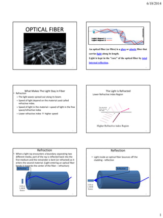
  • 1. 6/18/2014 1 OPTICAL FIBER 1 Basic principle Total Internal Reflection in Fiber 2 An optical fiber (or fibre) is a glass or plastic fiber that carries light along its length. Light is kept in the "core" of the optical fiber by total internal reflection. What Makes The Light Stay in Fiber • Refraction – The light waves spread out along its beam. – Speed of light depend on the material used called refractive index. – Speed of light in the material = speed of light in the free space/refractive index – Lower refractive index  higher speed 3 The Light is Refracted Lower Refractive index Region 4 This end travels further than the other hand Higher Refractive index Region Refraction • When a light ray encounters a boundary separating two different media, part of the ray is reflected back into the first medium and the remainder is bent (or refracted) as it enters the second material. (Light entering an optical fiber bends in towards the center of the fiber – refraction) 5 Refraction LED or LASER Source Reflection • Light inside an optical fiber bounces off the cladding - reflection 6 Reflection LED or LASER Source
  • 2. 6/18/2014 2 7 Critical Angle • If light inside an optical fiber strikes the cladding too steeply, the light refracts into the cladding - determined by the critical angle. (There will come a time when, eventually, the angle of refraction reaches 90o and the light is refracted along the boundary between the two materials. The angle of incidence which results in this effect is called the critical angle). 8 Critical Angle n1Sin X=n2Sin90o Angle of Incidence • Also incident angle • Measured from perpendicular • Exercise: Mark two more incident angles 9 Incident Angles Angle of Reflection • Also reflection angle • Measured from perpendicular • Exercise: Mark the other reflection angle 10 Reflection Angle Reflection Thus light is perfectly reflected at an interface between two materials of different refractive index if: – The light is incident on the interface from the side of higher refractive index. – The angle θ is greater than a specific value called the “critical angle”. 11 Angle of Refraction • Also refraction angle • Measured from perpendicular • Exercise: Mark the other refraction angle 12 Refraction Angle
  • 3. 6/18/2014 3 Angle Summary • Three important angles • The reflection angle always equals the incident angle 13 Refraction Angle Reflection Angle Incident Angles Refractive Index • n = c/v – c = velocity of light in a vacuum – v = velocity of light in a specific medium • light bends as it passes from one medium to another with a different index of refraction – air, n is about 1 – glass, n is about 1.4 14 Light bends in towards normal - lower n to higher n Light bends away from normal - higher n to lower n Snell’s Law • The amount light is bent by refraction is given by Snell’s Law: n1sin 1 = n2sin 2 • Light is always refracted into a fiber (although there will be a certain amount of Fresnel reflection) • Light can either bounce off the cladding (TIR) or refract into the cladding 15 Snell’s Law 16 Normal Incidence Angle( 1) Refraction Angle( 2) Lower Refractive index(n2) Higher Refractive index(n1)Ray of light Critical Angle Calculation • The angle of incidence that produces an angle of refraction of 90° is the critical angle – n1sin(qc) = n2sin(90°) – n1sin(qc) = n2 – qc = sin-1(n2 /n1) • Light at incident angles greater than the critical angle will reflect back into the core 17 Critical Angle, c n1 = Refractive index of the core n2 = Refractive index of the cladding OPTICAL FIBER CONSTRUCTION 18 Core – thin glass center of the fiber where light travels. Cladding – outer optical material surrounding the core Buffer Coating – plastic coating that protect the fiber.
  • 4. 6/18/2014 4 OPTICAL FIBER • The core, and the lower-refractive-index cladding, are typically made of high-quality silica glass, though they can both be made of plastic as well. 19 NA & ACCEPTANCE ANGLE DERIVATION • In optics, the numerical aperture (NA) of an optical system is a dimensionless number that characterizes the range of angles over which the system can accept or emit light.” • optical fiber will only propagate light that enters the fiber within a certain cone, known as the acceptance cone of the fiber. The half-angle of this cone is called the acceptance angle, θmax. 20 21 When a light ray is incident from a medium of refractive index n to the core of index n1, Snell's law at medium-core interface gives • Substituting for sin θr in Snell's law we get: By squaring both sides Thus, 22 • from where the formula given above follows. • NUMERICAL APERATURE IS • ACCEPTANCE ANGLE • θmax = 23 Definition:- • Acceptance angle:- • Acceptance angle is defined as the maximum angle of incidence at the interface of air medium and core medium for which the light ray enters into the core and travels along the interface of core and cladding. • Acceptance Cone:- • There is an imaginary cone of acceptance with an angle .The light that enters the fiber at angles within the acceptance cone are guided down the fiber core • Numerical aperture:- • Numerical aperture is defined as the light gathering capacity of an optical fiber and it is directly proportional to the acceptance angle. 24
  • 5. 6/18/2014 5 • Three common type of fiber in terms of the material used: • Glass core with glass cladding –all glass or silica fiber • Glass core with plastic cladding –plastic cladded/coated silica (PCS) • Plastic core with plastic cladding – all plastic or polymer fiber 25 Classification of Optical Fiber Plastic and Silica Fibers 26 BASED ON MODE OF PROPAGATION • Two main categories of optical fiber used in fiber optic communications are • multi-mode optical fiber • single-mode optical fiber. 27  Single-mode fiber  Carries light pulses along single path  Multimode fiber  Many pulses of light generated by LED travel at different angles 28 Based on the index profile 29 The boundary between the core and cladding may either be abrupt, in step-index fiber, or gradual, in graded- index fiber Step Index Fibers • A step-index fiber has a central core with a uniform refractive index. An outside cladding that also has a uniform refractive index surrounds the core; • however, the refractive index of the cladding is less than that of the central core. The refractive index profile may be defined as n(r) = n1 r < a (core) n2 r ≥ a (cladding) 30
  • 6. 6/18/2014 6 GRADED-INDEX • In graded-index fiber, the index of refraction in the core decreases continuously between the axis and the cladding. • This causes light rays to bend smoothly as they approach the cladding, rather than reflecting abruptly from the core-cladding boundary. 31 32 Figure.2.6 (a) (b) • multimode step-index fiber – the reflective walls of the fiber move the light pulses to the receiver • multimode graded-index fiber – acts to refract the light toward the center of the fiber by variations in the density • single mode fiber – the light is guided down the center of an extremely narrow core 33 Figure 2.10 Two types of fiber: (Top) step index fiber; (Bottom) Graded index fiber 34 Attenuation • Definition: a loss of signal strength in a lightwave, electrical or radio signal usually related to the distance the signal must travel. Attenuation is caused by: • Absorption • Scattering • Radiative loss 35 Losses • Losses in optical fiber result from attenuation in the material itself and from scattering, which causes some light to strike the cladding at less than the critical angle • Bending the optical fiber too sharply can also cause losses by causing some of the light to meet the cladding at less than the critical angle • Losses vary greatly depending upon the type of fiber – Plastic fiber may have losses of several hundred dB per kilometer – Graded-index multimode glass fiber has a loss of about 2–4 dB per kilometer – Single-mode fiber has a loss of 0.4 dB/km or less 36
  • 7. 6/18/2014 7 Macrobending Loss: • The curvature of the bend is much larger than fiber diameter. Lightwave suffers sever loss due to radiation of the evanescent field in the cladding region. As the radius of the curvature decreases, the loss increases exponentially until it reaches at a certain critical radius. For any radius a bit smaller than this point, the losses suddenly becomes extremely large. Higher order modes radiate away faster than lower order modes. 37 Micro bending Loss • Micro bending Loss: microscopic bends of the fiber axis that can arise when the fibers are incorporated into cables. The power is dissipated through the micro bended fiber, because of the repetitive coupling of energy between guided modes & the leaky or radiation modes in the fiber. 38 Dispersion • The phenomenon in an optical fibre whereby light photons arrive at a distant point in different phase than they entered the fibre. • Dispersion causes receive signal distortion that ultimately limits the bandwidth and usable length of the fiBer cable The two main causes of dispersion are:  Material (Chromatic) dispersion Waveguide dispersion Intermodal delay (in multimode fibres) 39 • Dispersion in fiber optics results from the fact that in multimode propagation, the signal travels faster in some modes than it would in others • Single-mode fibers are relatively free from dispersion except for intramodal dispersion • Graded-index fibers reduce dispersion by taking advantage of higher-order modes • One form of intramodal dispersion is called material dispersion because it depends upon the material of the core • Another form of dispersion is called waveguide dispersion • Dispersion increases with the bandwidth of the light source 40 Advantages of Optical Fibre • Thinner • Less Expensive • Higher Carrying Capacity • Less Signal Degradation& Digital Signals • Light Signals • Non-Flammable • Light Weight 41 Advantages of fiber optics 42  Much Higher Bandwidth (Gbps) - Thousands of channels can be multiplexed together over one strand of fiber  Immunity to Noise - Immune to electromagnetic interference (EMI).  Safety - Doesn’t transmit electrical signals, making it safe in environments like a gas pipeline.  High Security - Impossible to “tap into.”
  • 8. 6/18/2014 8 Advantages of fiber optics  Less Loss - Repeaters can be spaced 75 miles apart (fibers can be made to have only 0.2 dB/km of attenuation)  Reliability - More resilient than copper in extreme environmental conditions.  Size - Lighter and more compact than copper.  Flexibility - Unlike impure, brittle glass, fiber is physically very flexible. 43 Fiber Optic Advantages • greater capacity (bandwidth up to 2 Gbps, or more) • smaller size and lighter weight • lower attenuation • immunity to environmental interference • highly secure due to tap difficulty and lack of signal radiation 44 Disadvantages of fiber optics • Disadvantages include the cost of interfacing equipment necessary to convert electrical signals to optical signals. (optical transmitters, receivers) Splicing fiber optic cable is also more difficult. 45 Areas of Application • Telecommunications • Local Area Networks • Cable TV • CCTV • Optical Fiber Sensors 46 Formula Summary • Index of Refraction Snell’s Law Critical Angle Acceptance Angle Numerical Aperture 47 v c n 2211 sinsin nn 1 21 sin n n c 2 2 2 1 1 sin nn 2 2 2 1 sin nnNA STUDENTS YOU CAN ALSO REFER IT…… 48 http://hank.uoregon.edu/experiments/Dispersion-in- Optical-Fiber/Unit_1.6%20(2).pdf http://www1.ceit.es/asignaturas/comuopticas/pdf/chapter 4.pdf http://course.ee.ust.hk/elec342/notes/Lecture%206_attenu ation%20and%20dispersion.pdf 1 Engineering Physics by H Aruldhas, PHI India 2 Engineering Physics by B K Pandey , S. Chaturvedi, Cengage Learning 3 Resnick, Halliday and Krane, Physics part I and II, 5th Edition John Wiely 4 Engineering Physics by S.CHAND 5 Engineering Physics by G VIJIYAKUMARI
  • 9. 6/18/2014 1 Dielectrics are the materials having electric dipole moment permanently. Dipole: A dipole is an entity in which equal positive and negative charges are separated by a small distance.. DIPOLE moment (µEle ):The product of magnitude of either of the charges and separation distance b/w them is called Dipole moment. µe = q . x  coulmb.m All dielectrics are electrical insulators and they are mainly used to store electrical energy. Ex: Mica, glass, plastic, water & polar molecules… X q -q Introduction + Electric field Dielectric atom + + + + + + + + _ _ _ _ _ _ _ __ dipole The relative permittivity(εr) is often known as dielectric const. of medium it can given by, εr=ε/ε0 Dielectric constant is ratio of permittivity of medium to permittivity of free space. The value of capacitance of capacitor is given by, C0=εrε0A/d By this eqn we can say that high εr increases capacity of capacitor. Polar and Nonpolarized Molecules Non-polar Molecules : The Dielectric material in which there is no permanent dipole existence in absence of an external field is ….. O=O N N Cl-Cl F-F Br-Br I-I 2 – Compoundsmade of molecules which are symmetrically shaped carbon tetra fluoride CF4 propane C3H8 methane CH4 carbon tetra fluoride CCl4, carbon dioxide O=C=O Polar Molecules The Dielectric material in which there is permanent dipole existence even in absence of an external field is ….. HCl hydrogen chloride carbon monoxide C O 2 – molecules with O, N, or OH at one end – asymmetrical e.g.; CH2Cl2,CH3Cl water H2O unbounded electron pairs bend the molecule ammonia nitrogen trihydride NH3 alcohols methanol CH3OH
  • 10. 6/18/2014 2 Identify each of the following molecules as 1) polar or 2) nonpolarized. Explain. A. PBr3 B. HBr C. Br2 D. SiBr4 7 Identify each of the following molecules as 1) polar or 2) nonpolarized. Explain. A. PBr3 1) pyramidal; dipoles don’t cancel; polar B. HBr 1) linear; one polar bond (dipole); polar C. Br2 2) linear; nonpolarized bond; nonpolarized D. SiBr4 2) tetrahedral; dipoles cancel; no polar 8 As shown in fig. when an electric field is applied to dielectric material their negative & positive charges tend to align in equilibrium position.  They produce electric dipole inside the material.  This phenomenon is known as Polarization.  It can be represented by, P=polarization μ= dipole moment V=Volume  Unit=Cm-2  Now dipole moment depends upon applied electric field.  α polarizability of material. P V   E P E P E         + + + + + + + + - - - - - - - - E0 - - - - - - - - - - - - - - - - - - - - - - ++ -- ++ -- ++ -- ++ -- ++ -- ++ -- ++ -- ++ -- ++ -- ++ -- ++ -- + q - q - q + q - q + q + + + + + + + + + + + + + + + + + + + + + + E0  In absence of dielectric  In presence of dielectric 0 0 0 0 0 .E ds q q E A q E A        0 0 0 0 0 . ' ' ' E ds q q q q EA q q E A A            
  • 11. 6/18/2014 3  V=Ed  So  Now 0 0 d E V k E V   0 0 0 0 0 0 0 ' ' , 1 , ' (1 ) E q E k kA q q E A A q q q So kA A A then q q k               0 0 So, . ' 1 (1 ) q . E ds q q q q k k k E ds q            This relation true is for parallel plate capacitor Which is Gauss’s law for dielectrics  The resultant dielectric field is given by, Where, E=Electric field D=Flux Density or Displacement vector P=Polarization 0 0 0 0 0 0 ' ' , , , D p q q E A A q now P A q P E A q E P A q now D A So E P                     Electric susceptibility: The polarization vector P is proportional to the total electric flux density and direction of electric field. Therefore the polarization vector can be written 0 0 0 0 ( 1) 1 e e r e r P E P E E E                 Displacement vector, 0 0 0 r 0 0 0 D E P Now,P= ( - ) E P (or) ( . - ) E P ( 1) . P W here,( 1) r r E E                     1. Electron polarization 2. Ionic polarization 3. Orientation polarization 4. Space charge polarization
  • 12. 6/18/2014 4  When no external field is applied nucleus of atom is like in fig. (a)  When external field is applied, displacement in opposite direction is observed between nucleus & electrons due to this dipole moment is induced.  This type of polarization is called Electronic polarization.  Ex. Germanium, Silicon, Diamond etc… 19 + - + - - Electric Field(a) (b)  Some materials like ionic crystal does not possess permanent dipole moment.  Fig. (a) shows natural arrangement of ionic crystal. When Ele. Field is applied on this type of material displacement of ions is observed.  Due to an external electric field a positive & negative ion displaces in the direction opposite to each other due to which distance between them is reduced & ionic polarization is generated.  Ionic polarization is observed in materials like NaCl, KBr, KCl etc…  Let us consider simple example of NaCl crystal.  As shown in fig. when crystal is placed in an external electric field Na+ ion displaces in one direction & Cl- ion goes in opposite direction.  Some molecules like H2O, HCl having permanent dipole moment p0.  In the absence of a field, individual dipoles are arranged in random way, so net average dipole moment in a unit volume is zero as shown in fig. (b).  A dipole such as HCl placed in a field experiences a torque that tries to rotate it to align p0 with the field E.  In the presence of an applied field, the dipoles try to rotate to align parallel to each other in direction of electric field fig (d).  This type of polarization is Orientation polarization.  This type of polarization occurs only in polar substances like H2O, CH3Cl when they are placed in external field.  A crystal with equal number of mobile positive ions and fixed negative ions.  In the absence of a field, there is no net separation between all the positive charges and all the negative charges.
  • 13. 6/18/2014 5  In the presence of an applied field, the mobile positive ions migrate toward the negative charges and positive charges in the dielectric.  The dielectric therefore exhibits Space charge or interfacial polarization. . ? . . dW F dr F dW qE dr dW E dp p p P lA V       0 0 0 2 0 2 0 ( 1) . . .( 1) . . .( 1) . 1 ( 1) E 2 1 ( 1) E 2 ? r r r r r p PV dW EVdP P E dW E V dE dW E V dE W V W V U                          References: Engineering physics By Dr. M N Avadhnulu, S Chand publication Engineering physics by K Rajgopalan http://web.mit.edu/viz/EM/visualizations/coursenote s/modules/guide05.pdf
  • 14. 6/18/2014 1 Band Theory of Solid  Objectives • Effective Mass of electron • Concept of Holes • Energy Band Structure of Solids:  Conductors, Insulators and Semiconductors • Semiconductors  Intrinsic and Extrinsic Semiconductors • Type of diodes  Simple Diode  Zener Diode  Effective Mass of electron An electron moving in the solid under the influence of the crystal potential is subjected to an electric field. We expect an external field to accelerate the electron, increasing E and k and change the electron’s state. dt dx dx dV e dt dV e dt d eV and dk d gv  1 gv dx dV e dt dk dk d dx dV ek dt d gv dx dV e dt dk gv   eEk dt d  dt dk dk d dk d dk d dt d dt dv a g  11 k dt d dk d dt dk dk d   2 2 22 2 11 eE = F e 1 m  Concept of Holes Consider a semiconductor with a small number of electrons excited from the valence band into the conduction band. If an electric field is applied, • the conduction band electrons will participate in the electrical current • the valence band electrons can “move into” the empty states, and thus can also contribute to the current.
  • 15. 6/18/2014 2  Concept of Holes If we describe such changes via “movement” of the “empty” states – the picture will be significantly simplified. This “empty space” is called a Hole. “Deficiency” of negative charge can be treated as a positive charge. Holes act as charge carriers in the sense that electrons from nearby sites can “move” into the hole. Holes are usually heavier than electrons since they depict collective behavior of many electrons. Electrical current for holes and electrons in the same direction • To understand hole motion, one requires another view of the holes, which represent them as electrons with negative effective mass m*. • For example the movement of the hole think of a row of chairs occupied by people with one chair empty, and to move all people rise all together and move in one direction, so the empty spot moves in the same direction  Energy Band Structure of Solids Conductor, Semiconductor and Insulator In isolated atoms the electrons are arranged in energy levels.  Energy Band in Solid The following are the important energy band in solids:  Valence band  Conduction band  Forbidden energy gap or Forbidden band Valance band The band of energy occupied by the valance electrons is called valence band. The electrons in the outermost orbit of an atom are known as valance electrons. This band may be completely or partial filled. Electron can be move from one valance band to the conduction band by the application of external energy.
  • 16. 6/18/2014 3  Conduction band The band of energy occupied by the conduction electrons is called conduction band. This is the uppermost band and all electrons in the conduction band are free electrons. The conduction band is empty for insulator and partially filled for conductors.  Forbidden Energy Gap or Forbidden band The gap between the valance band and conduction band on energy level diagram known as forbidden band or energy gap. Electron are never found in the gap. Electrons may jump from back and forth from the bottom of valance band to the top of the conduction band. But they never come to rest in the forbidden band.  According to the classical free electron theory, materials are classified in to three types:  Conductors  Semiconductors  Insulators Conductors There is no forbidden gap and the conduction band and valence band are overlapping each other between and hence electrons are free to move about. Examples are Ag, Cu, Fe, Al, Pb ….  Conductor are highly electrical conductivity.  So, in general electrical resistivity of conductor is very low and it is of the order of 10-6 Ω cm.  Due to the absence of the forbidden gap, there is no structure for holes.  The total current in conductor is simply a flow of electrons.  For conductors, the energy gap is of the order of 0.01 eV. Semiconductors Semiconductors are materials whose electrical resistivity lies between insulator and conductor. Examples are silicon (Si), germanium (Ge) ….  The resistivity of semiconductors lie between 10-4 Ω cm to 103 Ω cm at room temperature.  At low temperature, the valence band is all most full and conduction band is almost empty. The forbidden gap is very small equal to 1 eV.  Semiconductor behaves like an insulator at low temperature. The most commonly used semiconductor is silicon and its band gap is 1.21 eV and germanium band gap is 0.785 eV. When a conductor is heated its resistance increases; The atoms vibrate more and the electrons find it more difficult to move through the conductor but, in a semiconductor the resistance decreases with an increase in temperature. Electrons can be excited up to the conduction band and Conductivity increases.
  • 17. 6/18/2014 4 Insulators In insulator, the valence band is full but the conduction band is totally empty. So, free electrons from conduction band is not available.  In insulator the energy gap between the valence and conduction band is very large and its approximately equal to 5 eV or more.  Hence electrons cannot jump from valence band to the conduction band. So, a very high energy is required to push the electrons to the conduction band.  The electrical conductivity is extremely small.  The resistivity of insulator lie between 103 to 1017 Ωm, at the room temperature  Examples are plastics, paper …..  Types of semiconductors Semiconductors Intrinsic Semiconductor Extrinsic Semiconductor p - type n - type  Intrinsic Semiconductor  The intrinsic semiconductor are pure semiconductor materials.  These semiconductors posses poor conductivity.  The elemental and compound semiconductor can be intrinsic type.  The energy gap in semiconductor is very small.  So even at the room temperature, some of electrons from valance band can jump to the conduction band by thermal energy.  The jump of electron in conduction band adds one conduction electron in conduction band and creates a hole in the valence band. The process is called as “generation of an electron–hole pair”.  In pure semiconductor the no. of electrons in conduction band and holes in holes in valence bands are equal.  Extrinsic Semiconductor  Extrinsic semiconductor is an impure semiconductor formed from an intrinsic semiconductor by adding a small quantity of impurity atoms called dopants.  The process of adding impurities to the semiconductor crystal is known as doping.  This added impurity is very small of the order of one atom per million atoms of pure semiconductor.  Depending upon the type of impurity added the extrinsic semiconductors are classified as: (1) p – type semiconductor (2) n – type semiconductor The application of band theory to n-type and p- type semiconductors shows that extra levels have been added by the impurities. In n-type material there are electron energy levels near the top of the band gap so that they can be easily excited into the conduction band. In p-type material, extra holes in the band gap allow excitation of valence band electrons, leaving mobile holes in the valence band. p – type semiconductor The addition of trivalent impurities such as boron, aluminum or gallium to an intrinsic semiconductor creates deficiencies of valence electrons,called "holes". It is typical to use B2H6 diborane gas to diffuse boron into the silicon material.
  • 18. 6/18/2014 5 n – type semiconductor The addition of pentavalent impurities such as antimony, arsenic or phosphorous contributes free electrons, greatly increasing the conductivity of the intrinsic semiconductor. Phosphorous may be added by diffusion of phosphine gas (PH3).  Simple Diode (p n- junction Diode)  The two terminals are called Anode and Cathode.  At the instant the two materials are “joined”, electrons and holes near the junction cross over and combine with each other.  Holes cross from P-side to N-side and Free electrons cross from N-side to P-side.  At P-side of junction, negative ions are formed.  At N-side of junction, positive ions are formed. Depletion region is the region having no free carriers. Further movement of electrons and holes across the junction stops due to formation of depletion region. Depletion region acts as barrier opposing further diffusion of charge carriers. So diffusion stops within no time. Current through the diode under no-bias condition is zero. Positive of battery connected to n-type material (cathode). Negative of battery connected to p-type material (anode). Reverse bias…..  Free electrons in n-region are drawn towards positive of battery, Holes in p-region are drawn towards negative of battery.  Depletion region widens, barrier increases for the flow of majority carriers.  Majority charge carrier flow reduces to zero.  Minority charge carriers generated thermally can cross the junction – results in a current called “reverse saturation current” Is , Is is in micro or nano amperes or less. Is does not increase “significantly” with increase in the reverse bias voltage Forward bias  Positive of battery connected to p-type (anode)  Negative of battery connected to n-type (cathode)
  • 19. 6/18/2014 6 Forward bias…  Electrons in n-type are forced to recombine with positive ions near the boundary, similarly holes in p- type are forced to recombine with negative ions.  Depletion region width reduces.  An electron in n-region “sees” a reduced barrier at the junction and strong attraction for positive potential.  As forward bias is increased, depletion region narrows down and finally disappears – leads to exponential rise in current.  Forward current is measured in milli amperes  Zener Diode A diode which is heavily doped and which operates in the reverse breakdown region with a sharp breakdown voltage is called a Zener diode. This is similar to the normal diode except that the line (bar) representing the cathode is bent at both side ends like the letter Z for Zener diode. In simple diode the doping is light; as a result, the breakdown voltage is high and not sharp. But if doping is made heavy, then the depletion layers becomes very narrow and even the breakdown voltage gets reduced to a sharp value.  Working Principle The reverse breakdown of a Zener diode may occur either due to Zener effect or avalanche effect. But the Zener diode is primarily depends on Zener effect for its working.  When the electrical field across the junction is high due to the applied voltage, the Zener breakdown occurs because of breaking of covalent bonds and produces a large number of electrons and holes which constitute a steep rise in the reverse saturation current (Zener current IZ). This effect is called as Zener effect.  Zener current IZ is independent of the applied voltage and depends only on the external resistance. I-V characteristic of a Zener diode The forward characteristic is simply that of an ordinary forward biased junction diode. Under the reverse bias condition, the breakdown of a junction occurs. Its depends upon amount of doping. It can be seen from above figure as the reverse voltage is increased the reverse current remains negligibly small up to the knee point (K) of the curve.
  • 20. 6/18/2014 7  At point K, the effect of breakdown process beings. The voltage corresponding to the point K in figure is called the Zener breakdown voltage or simply Zener voltage (VZ), which is very sharp compared to a simple p-n junction diode. Beyond this voltage the reverse current (IZ) increases sharply to a high value.  The Zener diode is not immediately burnt just because it has entered the breakdown region.  The Zener voltage VZ remains constant even when Zener current IZ increases greatly. The maximum value of current is denoted by IZ max and the minimum current to sustain breakdown is denoted by IZ min. By two points A and B on the reverse VI characteristic, the Zener resistance is given by the relation, rz = ( Δ VZ / Δ IZ) -----(1)  Zener diode Applications: I. Zener diodes are used as a voltage regulator. II. They are used in shaping circuits as peak limiters or clippers. III. They are used as a fixed reference voltage in transistor biasing and for comparison purpose. IV. They are used for meter protection against damage from accidental application of excessive voltage.
  • 21. 6/18/2014 1 LASER Light Amplification by Stimulated Emission of Radiation  Objectives… Introduction and understand the principle of LASER • Light Amplification by Stimulated Emission of Radiation • Absorption • Spontaneous Emission • Stimulated Emission • Population Inversion • Optical Pumping  Objectives…  Characteristics or Properties of Laser Light • Coherence • High Intensity • High directionality • High monochromaticity Laser light is highly powerful and it is capable of propagating over long distances and it is not easily absorbed by water. Introduction • LASER “Light Amplification by Stimulated Emission of Radiation” • MASER (1939 Towner) “Microwave Amplification by Stimulated Emission of Radiation” • Stimulated Emission - Einstein in 1917. • Ruby Crystal LASER - Maiman, California in 1960. • He-Ne LASER - Ali Javan in 1961. • Diode LASER- Hall in 1962.  Light having following Properties  Wavelength  Frequency  Amplitude  Phase  Coherence/Incoherence  Velocity  Direction Absorption • E1 = Ground state • E2 = Excited State • E = hν (Photon Energy)
  • 22. 6/18/2014 2 • According to Bohr’s law atomic system is characterized by discrete energy level. • When atoms absorb or release energy it transit upward or downward. • Lower level E1 & Excited level E2 • So, h ƒ = E2 – E1 • The rate of absorption depends on no. of atoms N1 present in E1 & spectral energy density u(ƒ) of radiation • So, P12 α N1 u(ƒ) • P12= B12N1 u(ƒ) Spontaneous Emission • E1 = Ground State • E2 = Excited State • E = E2 – E1 = ΔE = hν • System having atoms in excited state. • Goes to downward transition with emitting photons, hƒ = E1 – E2. • Emission is random, so if not in same phase becomes incoherent. • The transition depends on atoms in excited state N2. P12(spont) α N2 = A21 N2 • Where, A21 = Einstein coefficient for spontaneous Emission. we get Incoherent radiation forms heat by light amplification of radiation by spontaneous emission.  Stimulated Emission • System having atoms in excited state. • Goes to downward transition with emitting photons. • 2hƒ = E1 – E2. After applying photon energy hƒ. • Emission is depends on energy density u(ƒ) & No. of atoms in excited state N2 • P12(stimul) α u(ƒ) N2 = B21 N2 u(ƒ) • Where, B21 = Einstein coefficient for Stimulated Emission. • Thus one photon of energy hƒ stimulates two photons of energy hƒ in same phase & directions. So, we get coherent light amplification of radiation by stimulated emission.  Population Inversion • It is the process of increasing exited electrons in higher energy levels. • Due to this process the production of laser is possible. • The energy level between the ground state E1 (1st level) and exited state E3 (3rd level) is known as metastable state E2 (2nd level). • By optical pumping electrons from ground state jumps to exited state by absorbing photons.
  • 23. 6/18/2014 3 • The electrons remain only for 10-8 sec in exited state E3, so most of them jumps back to the ground state E1 by emitting photons. But some of them jumps to the metastable state E2. • They (electron) stay in metastable state for more then 10-3 sec. • So electron density increases in metastable state. • Thus the transitions are possible it takes more no. of electrons together and ν – (knew) 12 photon beam is produced which constitute laser beam.  Optical Pumping There are no of techniques for pumping a collection of atoms to an inverted state. • Optical pumping • Electrical discharge • Direct conversion When photon of blue green light incident on Ruby crystal, electrons from ground state absorbs and exited and jumps on higher energy state levels and comes back to metastable state. They increase population of electrons in metastable state. This process is called optical pumping which is done by flash tube.  Relation between Einstein’s ‘A’ and ‘B’ coefficients • Einstein obtained a mathematical expression for the existence of two different kinds of processes, (1) Spontaneous emission (2) Stimulated emission • Consider all atoms r in thermal equilibrium at T. • Radiation of freq. ƒ & energy density u(ƒ). • N1 & N2 r atoms in E1 & E2 respectively. • In equilibrium absorption rates & emission rates must be same. • i.e. B12 N1 u(ƒ) = A21 N2+ B21 N2 u(ƒ) A21 N2= u(ƒ) [B12N1 – B21N2] So, u(f) = [A21 N2 / (B12 N1 – B21 N2)] ---------(1) ------------(2) • Boltzmann distribution law, ------------(3) • So, -----------(4) • But, E2 – E1 = hf -----------(5) • So, -----------(6) 21 21 12 1 21 2 ( ) [ ] ƒ 1 A B u B N B N 1 2 / 1 0 / 2 0 E kT E kT N N e N N e 2 1( )/1 2 E E kTN e N h /1 2 ƒ kTN e N ---------- (7) • According to plank’s radiation formula, ----------- (8) • Where, B12 = B21 & A21 / B21 = ------------ (9) • So, Ratio of spontaneous to stimulated emission: --------- (10) 21 21 ƒ12 21 h / ƒ 1 ( ) [ ] kT e A B u B B 3 3 ƒh / 8 1 ( ) ( ) [ ] ƒ ƒ 1 kT u c h e 3 3 8 ƒh c 2 21 21 2 21 21 3 3 8 ( ) ( ) ( ) ƒ ƒ ƒ ƒ N A A h R B u B u ucN • So, --------- (11) --------- (12) • So, R = ---------- (13) If hƒ << kT, in thermal equilibrium, then R = << 1 • hƒ<<kT – Stimulated emission –Valid in microwave region (MASER) • hƒ>>kT – Spontaneous emission –Valid in visible region, incoherent 3 3 / 3 3 ƒh 8 ( ) 8 ƒ ƒ & ƒ ƒ 1 1 ( ) ( ) [ ] kT h u c u R h e c ƒh / 1[ ] kT e ƒh / 1[ ] kT e
  • 24. 6/18/2014 4  Types of LASER There are three types of lasers 1. Solid Laser (Ruby Laser) 2. Liquid Laser 3. Gas Laser ( He – Ne Laser, CO2 Laser)  Ruby Laser… To produce laser from solid, Ruby crystal is used. Ruby is an aluminum oxide crystal (Al2O3) in which some of the aluminum atoms have been replaced with Cr+3 chromium atoms (0.05% by weight). It was the first type of laser invented, and was first operated by Maiman in Research Laboratories on 1960. Chromium gives ruby its characteristic pink or red color by absorbing green and blue light. For a ruby laser, a crystal of ruby is formed into a cylinder. The ruby laser is used as a pulsed laser, producing red light at 6943 Å. Ruby crystal is surrounded by xenon tube. Ruby crystal is fully silvered at one side and partially silvered at the other end. A strong beam of blue green light is made to fall up on crystal from xenon tube and this light is absorbed by the crystal. Because of this, many electrons from ground state or normal state are raised to the excited state or higher state and electron falls to metastable state. During this transition photon is not emitted but excess energy of the electrons absorbed in crystal lattice. As electron drops to metastable state they remain there for certain time ~ 10-6 sec.  Thus the incident blue green light from tube increases the number of electron in metastable state and then the population inversion can be achieved.  If a light of different frequency is allowed to fall on this material, the electrons move back and forth between silvered ends of the crystal. While moving through they get stimulated and exiced electrons radiate energy.
  • 25. 6/18/2014 5 Thus readia photon has the same frequency as that of incident photon and is also in exactly same phase. When the intensity of light beam is increased the same process is repeated. Finally extremely intensified beam of light energies from the semi silvered side of the crystal. This way it is possible to get extremely intensified and coherent beam of light from the crystal. This beam is nothing but higher energetic beam – ie. LASER beam.  Applications of Ruby Laser… Ruby lasers have declined in use with the discovery of better lasing media. They are still used in a number of applications where short pulses of red light are required. Holography's around the world produce holographic portraits with ruby lasers, in sizes up to a meter squared. Many non-destructive testing labs use ruby lasers to create holograms of large objects such as aircraft tires to look for weaknesses in the lining. Ruby lasers were used extensively in tattoo and hair removal. Drawbacks of Ruby Laser… • The laser requires high pumping power because the laser transition terminates at the ground state and more than half of ground state atoms must be pumped to higher state to achieve population inversion. • The efficiency of ruby laser is very low because only green component of the pumping light is used while the rest of components are left unused. • The laser output is not continues but occurs in the form of pulses of microseconds duration. • The defects due to crystalline imperfections are also present in this laser.  Gaseous Laser (He – Ne Laser) A helium - neon laser, usually called a He-Ne laser, is a type of small gas laser. He-Ne lasers have many industrial and scientific uses, and are often used in laboratory demonstrations of optics. He-Ne laser is an atomic laser which employs a four-level pumping scheme.  The active medium is a mixture of 10 parts of helium to 1 part of neon. Neon atoms are centers and have energy levels suitable for laser transitions while helium atoms help efficient excitation of neon atoms. The most common wavelength is 6328 Å. These lasers produced powers in the range 0.5 to 50 mW in the red portion of the visible spectrum. They have long operating life of the order of 50,000 hrs.  Construction… It consists of a glass discharge tube of about typically 30 cm long and 1.5 cm diameter. The tube is filled with a mixture of helium and neon gases in the 10:1. Electrodes are provided in the tube to produce a discharge in the gas. They are connected to a high voltage power supply. The tube is hermetically sealed with glass windows oriented at Brewster angle to the tube. The cavity mirrors are arranged externally.
  • 26. 6/18/2014 6  Working… When the power is switched on , a high voltage of about 10 kV is applied across the gas.  It is sufficient to ionize the gas. The electrons and ions are produced in the process of discharge are accelerated toward the anode and cathode respectively. The electron have a smaller mass, they acquire a higher velocity. They transfer their kinetic energy to helium atoms through inelastic collisions.  The initial excitation effects only the helium atoms. They are in metastable state and cannot return in ground state by the spontaneous emission. The excited helium atoms can return to the ground state by transforming their energy to neon atoms through collision. This transformation take place when two colliding atoms have initial energy state. It is called resonant transfer of energy. So, the pumping mechanism of He-Ne Laser is when the helium atom in the metastable state collides with neon atom in the ground state the neon atom is excited and the helium atom drops back to the ground state. The role of helium atom is thus to excite neon atom and cause, population inversion. The probability of energy transfer from helium atoms to neon atoms is more as there are 10 atoms of helium per 1 neon atom in gas mixture. Without the Brewster windows, the light output is unpolarized, because of it laser output to be linearly polarized.   When the excited Ne atom passes from metastable state (3s) to lower level (2p), it emits photon of wavelength 632 nm.  This photon travels through the gas mixture parallel to the axis of tube, it is reflected back and forth by the mirror ends until it stimulates an excited Ne atom and causes it to emit a photon of 632nm with the stimulating photon.  The stimulated transition from (3s) level to (2p) level is laser transition. Although 6328 Å is standard wavelength of He-Ne Laser, other visible wavelengths 5430 Å (Green) 5940 Å (yellow-orange), 6120 Å (red-orange) can also produced. Overall gain is very low and is typically about 0.010 % to 0.1 %. The laser is simple practical and less expensive. The Laser beam is highly collimated, coherent and monochromatic. Applications of He-Ne Laser… The Narrow red beam of He-Ne laser is used in supermarkets to read bar codes. The He-Ne Laser is used in Holography in producing the 3D images of objects. He-Ne lasers have many industrial and scientific uses, and are often used in laboratory demonstrations of optics.
  • 27. 6/18/2014 7  Semiconductor Laser (Diode Laser) • A semiconductor laser is a laser in which a semiconductor serves as a photon source. • The most common semiconductor material that has been used in lasers is gallium arsenide. • Einstein’s Photoelectric theory states that light should be understood as discrete lumps of energy (photons) and it takes only a single photon with high enough energy to knock an electron loose from the atom it's bound to. • Stimulated, organized photon emission occurs when two electrons with the same energy and phase meet. The two photons leave with the same frequency and direction. P type Semiconductors • In the compound GaAs, each Ga atom has three electrons in its outermost shell of electrons and each As atom has five. • When a trace of an impurity element with two outer electrons, such as Zn (zinc), is added to the crystal. • The result is the shortage of one electron from one of the pairs, causing an imbalance in which there is a “hole” for an electron but there is no electron available. • This forms a p-type semiconductor. N type Semiconductors • When a trace of an impurity element with six outer electrons, such as Se (selenium), is added to a crystal of GaAs, it provides on additional electron which is not needed for the bonding. • This electron can be free to move through the crystal. • Thus, it provides a mechanism for electrical conductivity. • This type is called an n-type semiconductor. • Under forward bias (the p-type side is made positive) the majority carriers, electrons in the n- side, holes in the p-side, are injected across the depletion region in both directions to create a population inversion in a narrow active region. The light produced by radioactive recombination across the band gap is confined in this active region.  Application of Lasers…  Laser beam is used to measure distances of sun, moon, stars and satellites very accurately.  It can be used for measuring velocity of light, to study spectrum of matters, to study Raman effect.  It can be is used for increasing speed and efficiency of computer.  It is used for welding.  It is used in biomedical science.  It is used in 3D photography.  Application of Lasers…  It is used for communication, T. V. transmission, to search the objects under sea.  It can be used to predict earthquake.  Laser tools are used in surgery.  It is used for detection and treatment of cancer.  It is used to aline straight line for construction of dam, tunnels etc.  It is used in holography.  It is used in fiber optic communication.  It is also used in military, like LIDAR.  It is used to accelerate some chemical reactions.
  • 28. 6/18/2014 1 Special Theory of Relativity The dependence of various physical phenomena on relative motion of the observer and the observed objects, especially regarding the nature and behaviour of light, space, time, and gravity is called relativity. When we have two things and if we want to find out the relation between their physical property i.e.velocity,accleration then we need relation between them that which is higher and which is lower.In general way we reffered it to as a relativity. The famous scientist Einstein has firstly found out the theory of relativity and he has given very useful theories in relativity. Introduction to Relativity What is Special Relativity?  In 1905, Albert Einstein determined that the laws of physics are the same for all non-accelerating observers, and that the speed of light in a vacuum was independent of the motion of all observers. This was the theory of special relativity. FRAMES OF REFERENCE A Reference Frame is the point of View, from which we Observe an Object. A Reference Frame is the Observer it self, as the Velocity and acceleration are common in Both. Co-ordinate system is known as FRAMES OF REFERENCE Two types: 1. Inertial Frames Of Reference. 2. non-inertial frame of reference. FRAMES OF REFERENCE  We have already come across idea of frames of reference that move with constant velocity. In such frames, Newton’s law’s (esp. N1) hold. These are called inertial frames of reference.  Suppose you are in an accelerating car looking at a freely moving object (I.e., one with no forces acting on it). You will see its velocity changing because you are accelerating! In accelerating frames of reference, N1 doesn’t hold – this is a non-inertial frame of reference.
  • 29. 6/18/2014 2 Conditions of the Galilean Transformation  Parallel axes (for convenience)  K’ has a constant relative velocity in the x-direction with respect to K  Time (t) for all observers is a Fundamental invariant, i.e., the same for all inertial observers speed of frame NOT speed of object x ' x – v t y ' y z ' z Galilean Transform Galilean Transformation Inverse Relations Step 1. Replace with . Step 2. Replace ―primed‖ quantities with ―unprimed‖ and ―unprimed‖ with ―primed.‖ speed of frame NOT speed of object x x’ vt y y’ z z’ t t’ General Galilean Transformations ' ' ' tt yy vtxx 11 ' ' ' ' ' ' dt dt dt dt vv dt dy dt dy vvvv dt dx dt dx samethearetandt yy xx yy yy xx xx aa dt dv dt dv aa dt dv dt dv samethearetandt ' ' '0 ' ' inertial reference frame FamFam '  11 ' ' ' ' ' ' dt dt dt dt tt dt dy dt dy vuuv dt dx dt dx samethearetandt yy xx frame K frame K’ Newton’s Eqn of Motion is same at face-value in both reference frames PositionVelocityAcceleration Einstein’s postulates of special theory of relativity • The First Postulate of Special Relativity The first postulate of special relativity states that all the laws of nature are the same in all uniformly moving frames of reference. Einstein reasoned all motion is relative and all frames of reference are arbitrary. A spaceship, for example, cannot measure its speed relative to empty space, but only relative to other objects. Spaceman A considers himself at rest and sees spacewoman B pass by, while spacewoman B considers herself at rest and sees spaceman A pass by. Spaceman A and spacewoman B will both observe only the relative motion. The First Postulate of Special Relativity A person playing pool on a smooth and fast- moving ship does not have to compensate for the ship’s speed. The laws of physics are the same whether the ship is moving uniformly or at rest. The First Postulate of Special Relativity
  • 30. 6/18/2014 3 Einstein’s first postulate of special relativity assumes our inability to detect a state of uniform motion. Many experiments can detect accelerated motion, but none can, according to Einstein, detect the state of uniform motion. The First Postulate of Special Relativity The second postulate of special relativity states that the speed of light in empty space will always have the same value regardless of the motion of the source or the motion of the observer. The Second Postulate of Special Relativity Einstein concluded that if an observer could travel close to the speed of light, he would measure the light as moving away at 300,000 km/s. Einstein’s second postulate of special relativity assumes that the speed of light is constant. The Second Postulate of Special Relativity The speed of light is constant regardless of the speed of the flashlight or observer. The Second Postulate of Special Relativity The speed of light in all reference frames is always the same. • Consider, for example, a spaceship departing from the space station. • A flash of light is emitted from the station at 300,000 km/s—a speed we’ll call c. The speed of a light flash emitted by either the spaceship or the space station is measured as c by observers on the ship or the space station. Everyone who measures the speed of light will get the same value, c. The Second Postulate of Special Relativity 18 The Ether: Historical Perspective  Light is a wave.  Waves require a medium through which to propagate.  Medium as called the ―ether.‖ (from the Greek aither, meaning upper air)  Maxwell’s equations assume that light obeys the Newtonian-Galilean transformation.
  • 31. 6/18/2014 4 The Ether: Since mechanical waves require a medium to propagate, it was generally accepted that light also require a medium. This medium, called the ether, was assumed to pervade all mater and space in the universe. 20 The Michelson-Morley Experiment  Experiment designed to measure small changes in the speed of light was performed by Albert A. Michelson (1852 – 1931, Nobel ) and EdwardW. Morley (1838 – 1923).  Used an optical instrument called an interferometer that Michelson invented.  Device was to detect the presence of the ether.  Outcome of the experiment was negative, thus contradicting the ether hypothesis. Michelson-Morley Experiment(1887)  Michelson developed a device called an inferometer.  Device sensitive enough to detect the ether. Michelson-Morley Experiment(1887)  Apparatus at rest wrt the ether. Michelson-Morley Experiment(1887)  Light from a source is split by a half silvered mirror (M)  The two rays move in mutually perpendicular directions Michelson-Morley Experiment(1887)  The rays are reflected by two mirrors (M1 and M2) back to M where they recombine.  The combined rays are observed at T.
  • 32. 6/18/2014 5 Michelson-Morley Experiment(1887)  The path distance for each ray is the same (l1=l2).  Therefore no interference will be observed Michelson-Morley Experiment(1887)  Apparatus at moving through the ether. u ut Michelson-Morley Experiment(1887) First consider the time required for the parallel ray  Distance moved during the first part of the path is || || || ct L ut L t (c u ) (distance moved by light to meet the mirror) u ut Michelson-Morley Experiment(1887) (distance moved by light to meet the mirror))( || uc L t |||| utLct Similarly the time for the return trip is )( || uc L t The total time )()( || uc L uc L t u ut Michelson-Morley Experiment(1887) The total time || 2 2 2 2 ( ) ( ) 2 ( ) 2 / 1 L L t c u c u Lc c u L c u c u ut Michelson-Morley Experiment(1887) For the perpendicular ray we can write, ct vt 2 2 2 2 2 2 2 2 2 2 2 2 2 ( ) ( ) ct L ut L c t u t c u t L t c u (initial leg of the path) The return path is the same as the initial leg therefore the total time is 22 2 uc L t u ut
  • 33. 6/18/2014 6 Michelson-Morley Experiment(1887) ct vt 2 2 2 2 2 2 / 1 L t c u L c t u c The time difference between the two rays is, 1 21 2 2 || 2 2 2 2 2 3 2 1 1 2 2 L u u t t t c c c After a binomial expansi L u Lu t c c c on u ut Michelson-Morley Experiment(1887)  The expected time difference is too small to be measured directly!  Instead of measuring time, Michelson and Morley looked for a fringe change.  as the mirror (M) was rotated there should be a shift in the interference fringes. Results of the Experiment  A NULL RESULT  No time difference was found!  Hence no shift in the interference patterns Conclusion from Michelson-Morley Experiment  the ether didn’t exist. The Lorentz Transformation  We are now ready to derive the correct transformation equations between two inertial frames in Special Relativity, which modify the Galilean Transformation. We consider two inertial frames S and S’, which have a relative velocity v between them along the x-axis. x y z S x' y' z' S' v  Now suppose that there is a single flash at the origin of S and S’ at time , when the two inertial frames happen to coincide. The outgoing light wave will be spherical in shape moving outward with a velocity c in both S and S’ by Einstein’s Second Postulate.  We expect that the orthogonal coordinates will not be affected by the horizontal velocity:  But the x coordinates will be affected. We assume it will be a linear transformation:  But in Relativity the transformation equations should have the same form (the laws of physics must be the same). Only the relative velocity matters. So x y z c t x y z c t 2 2 2 2 2 2 2 2 2 2 y y z z x k x vt x k x vt a f a f k k  Consider the outgoing light wave along the x-axis (y = z = 0).  Now plug these into the transformation equations:  Plug these two equations into the light wave equation: x ct x ct in frame S' in frame S 1 / & 1 / x k x vt k ct vt kct v c x k x vt k ct vt kct v c ct x kct v c ct x kct v c t kt v c t kt v c 1 1 1 1 / / / / a f a f a f a f  Plug t’ into the equation for t:  So the modified transformation equations for the spatial coordinates are:  Now what about time? t k t v c v c k v c k v c 2 2 2 2 2 2 1 1 1 1 1 1 / / / / a fa f c h x x vt y y z z a f x x vt x x vt x x vt vt a f a f a f inverse transformation Plug one into the other:
  • 34. 6/18/2014 7  Solve for t’:  So the correct transformation (and inverse transformation) equations are: 2 2 2 2 2 2 2 2 2 2 2 2 2 2 2 2 2 2 1 1 / 1 1 / / 1 / / x x vt vt x vt vt v c x vt vt v c xv c vt vt t xv c vt v t t vx c x x vt x x vt y y y y z z z z t t vx c t t vx c a f a f c h c h/ / 2 2 The Lorentz Transformation Application of Lorentz Transformation  Time Dilation  We explore the rate of time in different inertial frames by considering a special kind of clock – a light clock – which is just one arm of an interferometer. Consider a light pulse bouncing vertically between two mirrors. We analyze the time it takes for the light pulse to complete a round trip both in the rest frame of the clock (labeled S’), and in an inertial frame where the clock is observed to move horizontally at a velocity v (labeled S).  In the rest frame S’ t L c t L c t t L c 1 2 1 2 2 = tim e up = tim e dow n = m irror m irror L  Now put the light clock on a spaceship, but measure the roundtrip time of the light pulse from the Earth frame S: t t t t c L v t c t L c v t t L c v t L c v c v c 1 2 2 2 2 2 2 2 2 2 2 2 2 2 2 2 2 2 2 2 2 4 4 4 4 2 1 1 1 time up time down The speed of light is still in this frame, so / / / / / c h L c t / 2 v t / 2  So the time it takes the light pulse to make a roundtrip in the clock when it is moving by us is appears longer than when it is at rest. We say that time is dilated. It also doesn’t matter which frame is the Earth and which is the clock. Any object that moves by with a significant velocity appears to have a clock running slow. We summarize this effect in the following relation: 2 2 1 2 , 1, 1 / L t cv c  Length Contraction  Now consider using a light clock to measure the length of an interferometer arm. In particular, let’s measure the length along the direction of motion.  In the rest frame S’:  Now put the light clock on a spaceship, but measure the roundtrip time of the light pulse from the Earth frame S: L c 0 2 1 2 1 2 1 1 1 2 2 2 time out, time backt t t t t L L vt ct t c v L L vt ct t c v A A’ C C’ vt1L  In other words, the length of the interferometer arm appears contracted when it moves by us. This is known as the Lorentz-Fitzgerald contraction. It is closely related to time dilation. In fact, one implies the other, since we used time dilation to derive length contraction. 1 2 2 2 2 2 2 2 2 2 0 2 2 2 2 1 1 / 1 / 2 But, from time dilation 1 / 1 1 1 / Lc L t t t c v c v c ct L v c t v c L L v c
  • 35. 6/18/2014 8 Engineering physics By Dr. M N Avadhnulu, S Chand publication ENGINEERING PHYSICS ABHIJIT NAYAK http://www.maths.tcd.ie/~cblair/notes/specrel.pdf http://www.newagepublishers.com/samplechapter/0 00485.pdf
  • 36. 6/18/2014 1 Superconductivity Introduction of superconductivity • Electrical resistivity ↓ Temp. ↓ • 0 º K Electrical resistivity is 0 for perfectly pure metal • Any metal can’t be perfectly pure. • The more impure the metal Electrical resistivity ↑ • Certain metals when they cooled their electrical resistivity decreases but at Tc resistivity is 0 this state of metal is called __________. • Finder – K Onnes 1911 Properties of Superconductors Electrical Resistance • Zero Electrical Resistance • Defining Property • Critical Temperature • Quickest test • 10-5Ωcm Effect of Magnetic Field Critical magnetic field (HC) – Minimum magnetic field required to destroy the superconducting property at any temperature H0 – Critical field at 0K T - Temperature below TC TC - Transition Temperature Element HC at 0K (mT) Nb 198 Pb 80.3 Sn 30.9 Superconducting Normal T (K) TC H0 HC 2 C 0 C T H H 1 T Effect of Electric Current • Large electric current – induces magnetic field – destroys superconductivity • Induced Critical Current iC = 2πrHC Persistent Current • Steady current which flows through a superconducting ring without any decrease in strength even after the removal of the field • Diamagnetic property i Meissner effect • When Superconducting material cooled bellow its Tc it becomes resistenceless & perfect diamagnetic. • When superconductor placed inside a magnetic field in Tc all magnetic flux is expelled out of it the effect is called Meissner effect. • Perfect diamagnetism arises from some special magnetic property of Superconductor.
  • 37. 6/18/2014 2 • If there is no magnetic field inside the superconductor relative permeability or diamagnetic constant μr =0. • Total magnetic induction B is, • If magnetic induction B=0 then, 0 ( )B H M 0 0 ( )H M M H 1 m M H Magnetic Flux Quantisation • Magnetic flux enclosed in a superconducting ring = integral multiples of fluxon • Φ = nh/2e = n Φ0 (Φ0 = 2x10-15Wb) Effect of Pressure • Pressure ↑, TC ↑ • High TC superconductors – High pressure Thermal Properties • Entropy & Specific heat ↓ at TC • Disappearance of thermo electric effect at TC • Thermal conductivity ↓ at TC – Type I superconductors Stress • Stress ↑, dimension ↑, TC ↑, HC affected Frequency • Frequency ↑, Zero resistance – modified, TC not affected Impurities • Magnetic properties affected Size • Size < 10-4cm – superconducting state modified General Properties • No change in crystal structure • No change in elastic & photo-electric properties • No change in volume at TC in the absence of magnetic field Isotope Effect • Maxwell • TC = Constant / Mα • TC Mα = Constant (α – Isotope Effect coefficient) • α = 0.15 – 0.5 • α = 0 (No isotope effect) • TC√M = constant Classification & characterization of super conductor • Type I or soft super conductor – Exhibit complete Meissner effect. – Bellow Hc super conductor above Hc Normal – Value of Hc is order of 0.1 T. – Aluminum, lead & Indium are type I super conductor – Not used as strong electromagnets • Type II or Hard super conductor – Exhibit complete Meissner effect bellow a certain critical field Hc1 at this point diamagnetism & superconductivity ↓. This state is mix state called vortex state. – At certain critical field Hc2 superconductivity disappears. – Niobium, Aluminum, silicon, ceramic are type II superconductors. – Pb is type I superconductor ac Hc =600 gauss at 4º K when a small impurity of In is added it becomes type II superconductor with Hc1 =400 gauss & Hc2 =1000 gauss.
  • 38. 6/18/2014 3 Types of Superconductors Type I • Sudden loss of magnetisation • Exhibit Meissner Effect • One HC = 0.1 tesla • No mixed state • Soft superconductor • Eg.s – Pb, Sn, Hg Type II • Gradual loss of magnetisation • Does not exhibit complete Meissner Effect • Two HCs – HC1 & HC2 (≈30 tesla) • Mixed state present • Hard superconductor • Eg.s – Nb-Sn, Nb-Ti-M HHC Superconducting Normal Superconducting -M Normal Mixed HC1 HC HC2 H London equation • According to London’s theory there are two type of electrons in SC – Super electrons – Normal electrons  At 0º K there are only Super electrons.  With increasing temp. Super electrons ↓ Normal electrons ↑ .  Let nn, un & ns, us are no. density & drift velocity of normal electrons & super electrons respectively.  Equation of motion of Super electrons under electric field is • Now current & drift velocity are related as s du m eE dt 2 ( ) s s s s s s s s s s s s s I n eA u J n eu J u n e J d n e e E dt n e Ed J dt m London's first equation • London's first equation gives absence of resistance. If E =0 then • Now from Maxwell's eqn 0s dJ dt ( ) d B E dt B A d A E dt d A E dt d A E dt 2 2 2 2 2 2 ( ) ( ) s s s s s s s s s s s s n e Ed J dt m d J m E dt n e d J m d A dt n e dt d m d A J dt n e dt m J A n e n e J A m London's second equation • Again from ampere Law Take curl on both sides 0 2 0 ( ) s s B J n e B A m 2 0 2 2 2 0 ( ) & ( ) s s n e B A m Now B B B A B n e B B B m A B
  • 39. 6/18/2014 4 2 2 0 2 0 2 2 2 2 2 ( ) 0 1 1 1 0 s s So B A n e B B m n e Assume m B B or B B λ is called London penetration depth Elements of BCS Theory • BCS Theory of Superconductivity • The properties of Type I superconductors were modeled successfully by the efforts of John Bardeen, Leon Cooper, and Robert Schrieffer in what is commonly called the BCS theory. • A key conceptual element in this theory is the pairing of electrons close to the Fermi level into Cooper pairs through interaction with the crystal lattice. • This pairing results form a slight attraction between the electrons related to lattice vibrations; the coupling to the lattice is called a phonon interaction. • Pairs of electrons can behave very differently from single electrons which are fermions and must obey the Pauli exclusion principle. • The pairs of electrons act more like bosons which can condense into the same energy level. • The electron pairs have a slightly lower energy and leave an energy gap above them on the order of 0.001eV which inhibits the kind of collision interactions which lead to ordinary resistivity. • For temperatures such that the thermal energy is less than the band gap, the material exhibits zero resistivity. • Bardeen, Cooper, and Schrieffer received the Nobel Prize in 1972 for the development of the theory of superconductivity. • Cooper Pairs • The transition of a metal from the normal to the superconducting state has the nature of a condensation of the electrons into a state which leaves a band gap above them. • This kind of condensation is seen with super fluid helium, but helium is made up of bosons -- multiple electrons can't collect into a single state because of the Pauli exclusion principle. • Froehlich was first to suggest that the electrons act as pairs coupled by lattice vibrations in the material. • This coupling is viewed as an exchange of phonons, phonons being the quanta of lattice vibration energy. • Experimental corroboration of an interaction with the lattice was provided by the isotope effect on the superconducting transition temperature. • The boson-like behavior of such electron pairs was further investigated by Cooper and they are called "Cooper pairs". • The condensation of Cooper pairs is the foundation of the BCS theory of superconductivity.
  • 40. 6/18/2014 5 • In the normal state of a metal, electrons move independently, whereas in the BCS state, they are bound into "Cooper pairs" by the attractive interaction. The BCS formalism is based on the "reduced" potential for the electrons attraction. • You have to provide energy equal to the 'energy gap' to break a pair, to break one pair you have to change energies of all other pairs. • This is unlike the normal metal, in which the state of an electron can be changed by adding a arbitrary small amount of energy. • The energy gap is highest at low temperatures but does not exist at temperatures higher than the transition temperature. • The BCS theory gives an expression of how the gap grows with the strength of attractive interaction and density of states. • The BCS theory gives the expression of the energy gap that depends on the Temperature T and the Critical Temperature Tc and is independent of the material: APPLICATIONSOF SUPER CONDUCTORS 1. Engineering • Transmission of power • Switching devices • Sensitive electrical instruments • Memory (or) storage element in computers. • Manufacture of electrical generators and transformers 2. Medical •Nuclear Magnetic Resonance (NMR) •Diagnosis of brain tumor •Magneto – hydrodynamic power generation JOSEPHSON DEVICES by Brian Josephson Principle: persistent current in d.c. voltage Explanation: • Consists of thin layer of insulating material placed between two superconducting materials. • Insulator acts as a barrier to the flow of electrons. • When voltage applied current flowing between super conductors by tunneling effect. • Quantum tunnelling occurs when a particle moves through a space in a manner forbidden by classical physics, due to the potential barrier involved
  • 41. 6/18/2014 6 Components of current • In relation to the BCS theory (Bardeen Cooper Schrieffer) mentioned earlier, pairs of electrons move through this barrier continuing the superconducting current. This is known as the dc current. • Current component persists only till the external voltage application. This is ac current. Josephson junctions • A type of electronic circuit capable of switching at very high speeds when operated at temperatures approaching absolute zero. • Named for the British physicist who designed it, • a Josephson junction exploits the phenomenon of superconductivity. Construction • A Josephson junction is made up of two superconductors, separated by a nonsuperconducting layer so thin that electrons can cross through the insulating barrier. • The flow of current between the superconductors in the absence of an applied voltage is called a Josephson current, • the movement of electrons across the barrier is known as Josephson tunneling. • Two or more junctions joined by superconducting paths form what is called a Josephson interferometer. Construction : Consists of superconducting ring having magnetic fields of quantum values(1,2,3..) Placed in between the two Josephson junctions Explanation : • When the magnetic field is applied perpendicular to the ring current is induced at the two junctions • Induced current flows around the ring thereby magnetic flux in the ring has quantum value of field applied • Therefore used to detect the variation of very minute magnetic signals Uses of Josephson devices • Magnetic Sensors • Gradiometers • Oscilloscopes • Decoders • Analogue to Digital converters • Oscillators • Microwave amplifiers • Sensors for biomedical, scientific and defence purposes • Digital circuit development for Integrated circuits • Microprocessors • Random Access Memories (RAMs)
  • 42. 6/18/2014 7 SQUIDS (Super conducting Quantum Interference Devices) Discovery: The DC SQUID was invented in 1964 by Robert Jaklevic, John Lambe, Arnold Silver, and James Mercereau of Ford Research Labs Principle : Small change in magnetic field, produces variation in the flux quantum. Construction: The superconducting quantum interference device (SQUID) consists of two superconductors separated by thin insulating layers to form two parallel Josephson junctions. Types Two main types of SQUID: 1) RF SQUIDs have only one Josephson junction 2)DC SQUIDs have two or more junctions. Thereby, • more difficult and expensive to produce. • much more sensitive. Fabrication • Lead or pure niobium The lead is usually in the form of an alloy with 10% gold or indium, as pure lead is unstable when its temperature is repeatedly changed. • The base electrode of the SQUID is made of a very thin niobium layer • The tunnel barrier is oxidized onto this niobium surface. • The top electrode is a layer of lead alloy deposited on top of the other two, forming a sandwich arrangement. • To achieve the necessary superconducting characteristics, the entire device is then cooled to within a few degrees of absolute zero with liquid helium Uses • Storage device for magnetic flux • Study of earthquakes • Removing paramagnetic impurities • Detection of magnetic signals from brain, heart etc. Cryotron The cryotron is a switch that operates using superconductivity. The cryotron works on the principle that magnetic fields destroy superconductivity. The cryotron is a piece of tantalum wrapped with a coil of niobium placed in a liquid helium bath. When the current flows through the tantalum wire it is superconducting, but when a current flows through the niobium a magnetic field is produced. This destroys the superconductivity which makes the current slow down or stop.
  • 43. 6/18/2014 8 Magnetic Levitated Train Principle: Electro-magnetic induction Introduction: Magnetic levitation transport, or maglev, is a form of transportation that suspends, guides and propels vehicles via electromagnetic force. This method can be faster than wheeled mass transit systems, potentially reaching velocities comparable to turboprop and jet aircraft (500 to 580 km/h). • Superconductors may be considered perfect diamagnets (μr = 0), completely expelling magnetic fields due to the Meissner effect. • The levitation of the magnet is stabilized due to flux pinning within the superconductor. • This principle is exploited by EDS (Electrodynamic suspension) magnetic levitation trains. •In trains where the weight of the large electromagnet is a major design issue (a very strong magnetic field is required to levitate a massive train) superconductors are used for the electromagnet, since they can produce a stronger magnetic field for the same weight. Why superconductor ? How to use a Super conductor • Electrodynamics suspension • In Electrodynamic suspension (EDS), both the rail and the train exert a magnetic field, and the train is levitated by the repulsive force between these magnetic fields. • The magnetic field in the train is produced by either electromagnets or by an array of permanent magnets. • The repulsive force in the track is created by an induced magnetic field in wires or other conducting strips in the track. • At slow speeds, the current induced in these coils and the resultant magnetic flux is not large enough to support the weight of the train. • For this reason the train must have wheels or some other form of landing gear to support the train until it reaches a speed that can sustain levitation. • Propulsion coils on the guide way are used to exert a force on the magnets in the train and make the train move forwards. • The propulsion coils that exert a force on the train are effectively a linear motor: An alternating current flowing through the coils generates a continuously varying magnetic field that moves forward along the track. • The frequency of the alternating current is synchronized to match the speed of the train. • The offset between the field exerted by magnets on the train and the applied field create a force moving the train forward. Advantages  No need of initial energy in case of magnets for low speeds One liter of Liquid nitrogen costs less than one liter of mineral water Onboard magnets and large margin between rail and train enable highest recorded train speeds (581 km/h) and heavy load capacity. Successful operations using high temperature superconductors in its onboard magnets, cooled with inexpensive liquid nitrogen Magnetic fields inside and outside the vehicle are insignificant; proven, commercially available technology that can attain very high speeds (500 km/h); no wheels or secondary propulsion system needed  Free of friction as it is “Levitating”
  • 44. 6/18/2014 9 Engineering physics By Dr. M N Avadhnulu, S Chand publication Engineering physics by G Vijayakumari http://www.cengage.com/resource_uploads/static_ resources/0534493394/4891/SerwayCh12- Superconductivity.pdf https://www.repository.cam.ac.uk/bitstream/handl e/1810/34597/Chapter%201.pdf?sequence=5 http://chabanoiscedric.tripod.com/NSCHSS.PDF http://www.physics.usyd.edu.au/~khachan/PTF/Sup erconductivity.pdf
  • 45. 1 Atomic Physics • “Classical Physics”: – developed in 15th to 20th century; – provides very successful description of “every day, ordinary objects” • motion of trains, cars, bullets,…. • orbit of moon, planets • how an engine works,.. • subfields: mechanics, thermodynamics, electrodynamics, • Quantum Physics: • developed early 20th century, in response to shortcomings of classical physics in describing certain phenomena (blackbody radiation, photoelectric effect, emission and absorption spectra…) • describes “small” objects (e.g. atoms ) Quantum Physics • QP is “weird and counterintuitive” • “Those who are not shocked when they first come across quantum theory cannot possibly have understood it” (Niles Bohr) • “Nobody feels perfectly comfortable with it “ (Murray Gell-Mann) • “I can safely say that nobody understands quantum mechanics” (Richard Feynman) BUT… • QM is the most successful theory ever developed by humanity underlies our understanding of atoms, molecules, condensed matter, nuclei, elementary particles • Crucial ingredient in understanding of stars, … Features of QP • Quantum physics is basically the recognition that there is less difference between waves and particles than was thought before • key insights: • light can behave like a particle • particles (e.g. electrons) are indistinguishable • particles can behave like waves (or wave packets) • waves gain or lose energy only in "quantized amounts“ • detection (measurement) of a particle wave will change suddenly into a new wave • quantum mechanical interference – amplitudes add • QP is intrinsically probabilistic • what you can measure is what you can know WAVE-PICTURE OF RADIATION— ENERGY FLOW I S CONTI N UOUS • Radio waves, microwaves, heat waves, light waves, UV- rays, x-rays and y-rays belong to the family of electromagnetic waves. All of them are known as radiation. • Electromagnetic waves consist of varying electric and magnetic fields traveling at the velocity of 'c'. The propagation of electromagnetic waves and their interaction with matter can be explained with the help of Maxwell's electromagnetic theory. • Maxwell's theory treated the emission of radiation by a source as a continuous process. • A heated body may be assumed to be capable of giving out energy that travels in the form of waves of all possible wavelengths. • In the same way, the radiation incident on a body was thought to be absorbed at all possible wavelengths. • The intensity of radiation is given by, I = 1E12 where E is the amplitude of the electromagnetic wave.
  • 46. 2 • The phenomena of interference, diffraction and polarization of electromagnetic radiation proved the wave nature of radiation. • Therefore, it is expected that it would explain the experimental observations made on thermal (heat) radiation emitted by a blackbody. Blackbody radiation and Planck hypothesis • Two patches of clouds in physics sky at the beginning of 20th century. • The speed of light  Relativity • The blackbody radiation  foundation of Quantum theory Blackbody radiation • Types of heat energy transmission are conduction, convection and radiation. • Conduction is transfer of heat energy by molecular vibrations not by actual motion of material. For example, if you hold one end of an iron rod and the other end of the rod is put on a flame, you will feel hot some time later. You can say that the heat energy reaches your hand by heat conduction. • Convection is transfer of heat by actual motion of. The hot-air furnace, the hot-water heating system, and the flow of blood in the body are examples. • Radiation The heat reaching the earth from the sun cannot be transferred either by conduction or convection since the space between the earth and the sun has no material medium. The energy is carried by electromagnetic waves that do not require a material medium for propagation. The kind of heat transfer is called thermal radiation. • Blackbody is defined as the body which can absorb all energies that fall on it. It is something like a black hole. No lights or material can get away from it as long as it is trapped. A large cavity with a small hole on its wall can be taken as a blackbody. •Blackbody radiation: Any radiation that enters the hole is absorbed in the interior of the cavity, and the radiation emitted from the hole is called blackbody radiation. Fig. 9.1 Blackbody concave.
  • 47. 3 LAWS OF BLACK BODY RADIATION 1. Stefan and Boltzmann‟s law: it is found that the radiation energy is proportional to the fourth power of the associated temperature. 4 M (T) T M(T) is actually the area under each curve, σ is called Stefan‟s constant and T is absolute temperature. 2. Wien‟s displacement law: the peak of the curve shifts towards longer wavelength as the temperature falls and it satisfies peak T b This law is quite useful for measuring the temperature of a blackbody with a very high temperature. You can see the example for how to measure the temperature on the surface of the sun. where b is called the Wien's constant. b=2.89X10⁻³ • The above laws describes the blackbody radiation very well. • The problem exists in the relation between the radiation power Mλ(T) and the wavelength λ. • Blackbody radiation has nothing to do with both the material used in the blackbody concave wall and the shape of the concave wall. • Two typical theoretical formulas for blackbody radiation : One is given by Rayleigh and Jeans and the other by Wein. 3.Rayleigh and Jeans In 1890, Rayleigh and Jeans obtained a formula using the classical electromagnetic (Maxwell) theory and the classical equipartition theorem of energy in thermotics. The formula is given by 2 3 8 kT E( ) c Rayleigh-Jeans formula was correct for very long wavelength in the far infrared but hopelessly wrong in the visible light and ultraviolet region. Maxwell‟s electromagnetic theory and thermodynamics are known as correct theory. The failure in explaining blackbody radiation puzzled physicists! It was regarded as ultraviolet Catastrophe (disaster). 4. Planck Radiation Law: hc E h Quantum energy Planck constant Frequency 34 15 h 6.626 10 J s 4.136 10 eV s 19 18 1eV 1.602 10 J 1J 6.242 10 eV
  • 48. 4 PLANCK'S QUANTUM HYPOTHESIS — Energy is quantized • Max Planck empirical formula explained the experimental observations. • In the process of formulation of the formula, he assumed that the atoms of the walls of the blackbody behave like small harmonic oscillators, each having a characteristic frequency of vibration, lie further made two radical assumptions about the atomic oscillators. • (i) An oscillating atom can absorb or mends energy in discrete units. The indivisible discrete unit of energy hs, is the smallest amount of energy which can be absorbed or emitted by the atom and is called an energy quantum. A quantum of energy has the magnitude given by E = hv where v is the frequency of radiation and „h' is a constant now known as the Planck's constant. • (ii) The energy of the oscillator is quantized. It can have only certain discrete amounts of energy En. En= nhv n=1,2,3…… • The hypothesis that radiant energy is emitted or absorbed basically in a discontinuous summer and in the form of quanta is known as the Planck's quantum hypothesis. • Planck's hypothesis states that radiant energy Is quantized and implies that an atom exists in certain discrete energy states. Such states arc called quantum stales and n is called the quantum number. • The atom emits or absorbs energy by jumping from one quantum state to another quantum state. The assumption of discrete energy states for an atomic oscillator (Fig.a) was a departure from the classical physics and our everyday experience. • If we take a mass-spring harmonic oscillator, it can receive any amount of energy form zero to some maximum value (Fig.b). Thus, in the realm of classical physics energy always appears to occur with continuous values and energy exchange between bodies involves any arbitrary amounts of energy. PARTICLE PICTURE OF RADIATION — Radiation is a stream of photons • Max Planck introduced the concept of discontinuous emission and absorption of radiation by bodies but he treated the propagation through space as occurring in the form of continuous waves as demanded by electromagnetic theory. • Einstein refined the Planck's hypothesis and invested the quantum with a clear and distinct identity.
  • 49. 5 • He successfully explained the experimental results of the photoelectric effect in 1905 and the temperature dependence of specific heats of solids in 1907 basing on Planck's hypothesis. • The photoelectric effect conclusively established that light behaves as a swam of particles. Einstein extended Planck's hypothesis as follows: 1. Einstein assumed that the light energy is not distributed evenly over the whole expanding wave front but rather remains concentrated in discrete quanta. He named the energy quanta as photons. Accordingly, a light beam is regarded as a stream of photons travelling with a velocity ' c' . 2. An electromagnetic wave having a frequency f contains identical photons, each having an energy hƒ. The higher the frequency of the electromagnetic wave, the higher is the energy content of each photon. 3. An electromagnetic wave would have energy hƒ if it contains only one photon. 2hv if it contains 2 photons and so on. Therefore, the intensity of a monochromatic light beam I. is related to the concentration of photons. N. present in the beam. Thus, I = N hƒ Note that according to electromagnetic theory, the intensity of a light beam is given by I = 1E12 4. When photons encounter matter, they impart all their energy to the panicles of matter and vanish. That is why absorption of radiation is discontinuous. The number of photons emitted by even a weak light source is enormously large and the human eye cannot register the photons separately and therefore light appears as a continuous stream. Thus, the discreteness of light is not readily apparent. The Photon • As the radiant energy is viewed as made up of spatially localized photons. we may attribute particle properties to photons. 1. Energy: The energy of a photon is determined by its frequency v and is given by E = hƒ. Using the relation ω= 2π and writing h/2π = ħ. we may express E= ħω 2. Velocity: Photons always travel with the velocity of light „c'. 3. Rest Mass: The rest mass of photon is zero since a photon can never be at rest. Thus, m0= 0 4. Relativistic mass: As photon travels with the velocity of light, it has relativistic mass. given by m= E/c2 = hv/c2 The Photon • As the radiant energy is viewed as made up of spatially localized photons. we may attribute particle properties to photons. 1. Energy: The energy of a photon is determined by its frequency v and is given by E = hƒ. Using the relation ω= 2π and writing h/2π = ħ. we may express E= ħω 2. Velocity: Photons always travel with the velocity of light „c'. 3. Rest Mass: The rest mass of photon is zero since a photon can never be at rest. Thus, m0= 0 4. Relativistic mass: As photon travels with the velocity of light, it has relativistic mass. given by m= E/c2 = hv/c2
  • 50. 6 5. Linear Momentum: The linear momentum associated with a photon may be expressed as p=E/c=hv/c= h/λ As the wave vector k= 2π/λ , p = hk/ 2π = ħk. 6. Angular Momentum: Angular momentum is also known as spin which is the intrinsic property of all microparticles. Photon has a spin of one unit. Thus. s = lħ. 7. Electrical Charge: Photons are electrically neutral and cannot be influenced by electric or magnetic fields. They cannot ionize matter. Example: Calculate the photon energies for the following types of electromagnetic radiation: (a) a 600kHz radio wave; (b) the 500nm (wavelength of) green light; (c) a 0.1 nm (wavelength of) X-rays. Solution: (a) for the radio wave, we can use the Planck-Einstein law directly 15 3 9 E h 4.136 10 eV s 600 10 Hz 2.48 10 eV (b) The light wave is specified by wavelength, we can use the law explained in wavelength: 6 9 hc 1.241 10 eV m E 2.26eV 550 10 m (c). For X-rays, we have 6 4 9 hc 1.241 10 eV m E 1.24 10 eV 12.4keV 0.1 10 m Photoelectric Effect The quantum nature of light had its origin in the theory of thermal radiation and was strongly reinforced by the discovery of the photoelectric effect. Fig. Apparatus to investigate the photoelectric effect that was first found in 1887 by Hertz. Photoelectric Effect In figure , a glass tube contains two electrodes of the same material, one of which is irradiated by light. The electrodes are connected to a battery and a sensitive current detector measures the current flow between them. The current flow is a direct measure of the rate of emission of electrons from the irradiated electrode. The electrons in the electrodes can be ejected by light and have a certain amount of kinetic energy. Now we change: (1) the frequency and intensity of light, (2) the electromotive force (e.m.f. or voltage), (3) the nature of electrode surface. It is found that:
  • 51. 7 (1). For a given electrode material, no photoemission exists at all below a certain frequency of the incident light. When the frequency increases, the emission begins at a certain frequency. The frequency is called threshold frequency of the material. The threshold frequency has to be measured in the existence of e.m.f. (electromotive force) as at such a case the photoelectrons have no kinetic energy to move from the cathode to anode . Different electrode material has different threshold frequency. (2). The rate of electron emission is directly proportional to the intensity of the incident light. Photoelectric current ∝ The intensity of light (3). Increasing the intensity of the incident light does not increase the kinetic energy of the photoelectrons. Intensity of light ∝ kinetic energy of photoelectron However increasing the frequency of light does increase the kinetic energy of photoelectrons even for very low intensity levels. Frequency of light ∝ kinetic energy of photoelectron (4). There is no measurable time delay between irradiating the electrode and the emission of photoelectrons, even when the light is of very low intensity. As soon as the electrode is irradiated, photoelectrons are ejected. (5) The photoelectric current is deeply affected by the nature of the electrodes and chemical contamination of their surface. In 1905, Einstein solved the photoelectric effect problem by applying the Planck‟s hypothesis. He pointed out that Planck‟s quantization hypothesis applied not only to the emission of radiation by a material object but also to its transmission and its absorption by another material object. The light is not only electromagnetic waves but also a quantum. All the effects of photoelectric emission can be readily explained from the following assumptions: (1) The photoemission of an electron from a cathode occurs when an electron absorbs a photon of the incident light; (2) The photon energy is calculated by the Planck‟s quantum relationship: E = hν. (3) The minimum energy is required to release an electron from the surface of the cathode. The minimum energy is the characteristic of the cathode material and the nature of its surface. It is called work function. Therefore we have the equation of photoelectric effect: 21 2 h A m v Photon energy Work function Photoelectron kinetic energy Using this equation and Einstein‟s assumption, you could readily explain all the results in the photoelectric effect: why does threshold frequency exist (problem)? why is the number of photoelectrons proportional to the light intensity? why does high intensity not mean high photoelectron energy (problem)? why is there no time delay (problem)?
  • 52. 8 Example: Ultraviolet light of wavelength 150nm falls on a chromium electrode. Calculate the maximum kinetic energy and the corresponding velocity of the photoelectrons (the work function of chromium is 4.37eV). Solution: using the equation of the photoelectric effect, it is convenient to express the energy in electron volts. The photon energy is 6 9 1.241 10 8.27 150 10 hc eV m E h eV mand 2 2 1 2 1 (8.27 4.37) 3.90 2 h A mv mv eV eV 19 19 19 2 2 1 1.602 10 1.602 10 1.602 10eV J N m kg m s ∴ 2 19 2 21 3.90 3.90 1.602 10 2 mv eV kg m s ∴ 19 6 31 2 3.90 12.496 10 1.17 10 / 9.11 10 eV v m s m Examples 1. The wavelength of yellow light is 5890 A. What is the energy of the photons in the beam? Empress in electron volts. 2. 77w light sensitive compound on most photographic films is silver bromide, Aglin A film is exposed when the light energy absorbed dissociates this molecule into its atoms. The energy of dissociation of Agllr is 23.9 k.catitnot Find the energy in electron volts, the wavelength and the frequency of the photon that is just able to dissociate a molecule of silver bromide. 3. Calculate the energy of a photon of blue light with a frequency of 6.67 x 10¹⁴ Hz. (State in eV) [2.76eV] 4. Calculate the energy of a photon of red light with a wavelength of 630 nm. [1.97eV] 5. Barium has a work function of 2.48 eV. What is the maximum kinetic energy of the ejected electron if the metal is illuminated by light of wavelength 450 nm? [0.28 eV] 6. When a 350nm light ray falls on a metal, the maximum kinetic energy of the photoelectron is 1.20eV. What is the work function of the metal? [2.3 eV] 7. A photon has 3.3 x 10⁻¹⁹ J of energy. What is the wavelength of this photon? 8. What is the energy of one quantum of 5.0 x 10¹⁴ Hz light?
  • 53. 6/18/2014 1 X - Rays Objectives • Introduction and production of X-Rays • Properties of X-Rays • Diffraction of X-Rays • The Bragg’s X-Ray spectrometer • Continuous spectra • Characteristics Radiation • Moseley’s law • Absorption of X-Ray • Compton effect • Applications of X-Rays Introduction of X-Rays • Rontgen discovered X-rays in 1985 during some experiments with a discharge tube. • He noticed that a screen coated with barium platinocyanide present at a distance from the discharge tube. Rontgen called these invisible radiations “X-rays”. Finally, he concluded that X-rays are produced due to the bombardment of cathode rays on the walls of the discharge tube. • X-rays are highly penetrating and it can pass through many solids. • X-rays occur beyond the UV region in the electromagnetic spectrum. • Their wavelengths range from 0.01 to 10 Å. Production or Generation of X-rays X-rays are produced by an X-ray tube. The schematic of the modern type of X-ray tube is shown in above figure. It is an evacuated glass bulb enclosing two electrodes, a cathode and an anode. The cathode consists of a tungsten filament which emits electrons when it heated. The electrons are focused into a narrow beam with the help of a metal cup S. The anode consists of a target material, made of tungsten or molybdenum, which is embedded in a copper bar. Water circulating through a jacket surrounding the anode and cools the anode. Further large cooling fins conduct the heat away to the atmosphere. • The face of the target is kept at an angle relative to the oncoming electron beam. A very high potential difference of the order of 50 kV is applied across the electrodes. The electrons emitted by the cathode are accelerated by the anode and acquire high energies of order of 105 eV. When the target suddenly stops these electrons, X-rays are emitted. • The magnetic field associated with the electron beam undergoes a change when the electrons are stopped and electromagnetic waves in the form of X-rays are generated.
  • 54. 6/18/2014 2 • The grater of the speed of the electron beam, the shorter will be the wavelength of the radiated X-rays. Only about 0.2 % of the electron beam energy is converted in to X-rays and the rest of the energy transforms into heat. It is for the reason that the anode is intensively cooled during the operation of X-ray tube. • The intensity of the electron beam depends on the number of electron leaving the cathode. The hardness of the X-rays emitted depends on the energy of the electron beam striking the target. It can be adjusted by varying the potential difference applied between the cathode and anode. Therefore, the larger potential difference, the more penetrating or harder X-rays.  Properties of X-Rays… They have relatively high penetrating power. They are classified into Hard X-rays & Soft X- rays. The X-rays which have high energy and short wavelength is known as Hard X-rays. The X-rays which have low energy and longer wavelength is known as Soft X-rays. X-rays causes the phenomenon of flouroscence. On passing through a gas X-rays ionize the gas.  Properties of X-Rays… They are absorbed by the materials through which they traverse. X-rays travel in straight line. Their speed in vacuum is equal to speed of light . X-rays can affect a photographic film. X-rays are undeflected by electric field or magnetic field.  Diffraction of X-Rays – Bragg’s law Consider a crystal as made out of parallel planes of ions, spaced a distance d apart. The conditions for a sharp peak in the intensity of the scattered radiation are: 1. That the X-rays should be secularly reflected by the ions in any one plane. 2. That the reflected rays from successive planes should interfere constructively. • Path difference between two rays reflected from adjoining planes: 2dsinθ, • For the rays to interfere constructively, this path difference must be an integral number of wavelength λ, nλ =2dsinθ ------- (1) Bragg angle is just the half of the total angle by which the incident beam is deflected. The Bragg’s X-Ray spectrometer • An X-ray diffraction experiment requires, • X-ray source • The sample • The detector • Depending on method there can be variations in these requirements. The X-ray radiation may either monochromatic or may have variable wave length. • Structures of polycrystalline sample and single crystals can be studied. The detectors used in these experiments are photographic film.
  • 55. 6/18/2014 3  The schematic diagram of Bragg’s X-ray spectrometer is given in above. • X-ray from an X-ray tube is collimated by passing team through slits S1 and S2. This beam is then allowed to fall on a single crystal mounted on a table which can be rotated about an axis perpendicular to the plane of incident of X-rays. The crystal behaves as a reflected grating and reflects X-rays. By rotating the table, the glancing angle θ at which the X-ray is incident on the crystal can be changed. The angle for which the intensity of the reflected beam is maximum gives the value of θ. The experiment is repeated for each plane of the crystal. For first order reflection n = 1 so that, λ = 2d sinθ; for n = 2, 2λ = 2d sinθ; ……., and so on. • A photographic plate or an ionization chamber is used to detect the rays reflected by the crystal.  Continuous or Bremsstrahlung X-rays • "Bremsstrahlung" means "braking radiation" and is retained from the original German to describe the radiation which is emitted when electrons are decelerated or "braked" when they are fired at a metal target. • Accelerated charges give off electromagnetic radiation, and when the energy of the bombarding electrons is high enough, that radiation is in the x-ray region of the electromagnetic spectrum. Continuous X-rays… Continuous X-rays… • It is characterized by a continuous distribution of radiation which becomes more intense and shifts toward higher frequencies when the energy of the bombarding electrons is increased. • The curves above are who bombarded tungsten targets with electrons of four different energies. • The continuous distribution of x-rays which forms the base for the two sharp peaks at left is called "Bremsstrahlung" radiation.  Characteristic X-rays • Characteristic X-rays are emitted from heavy elements when their electrons make transitions between the lower atomic energy levels.