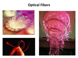
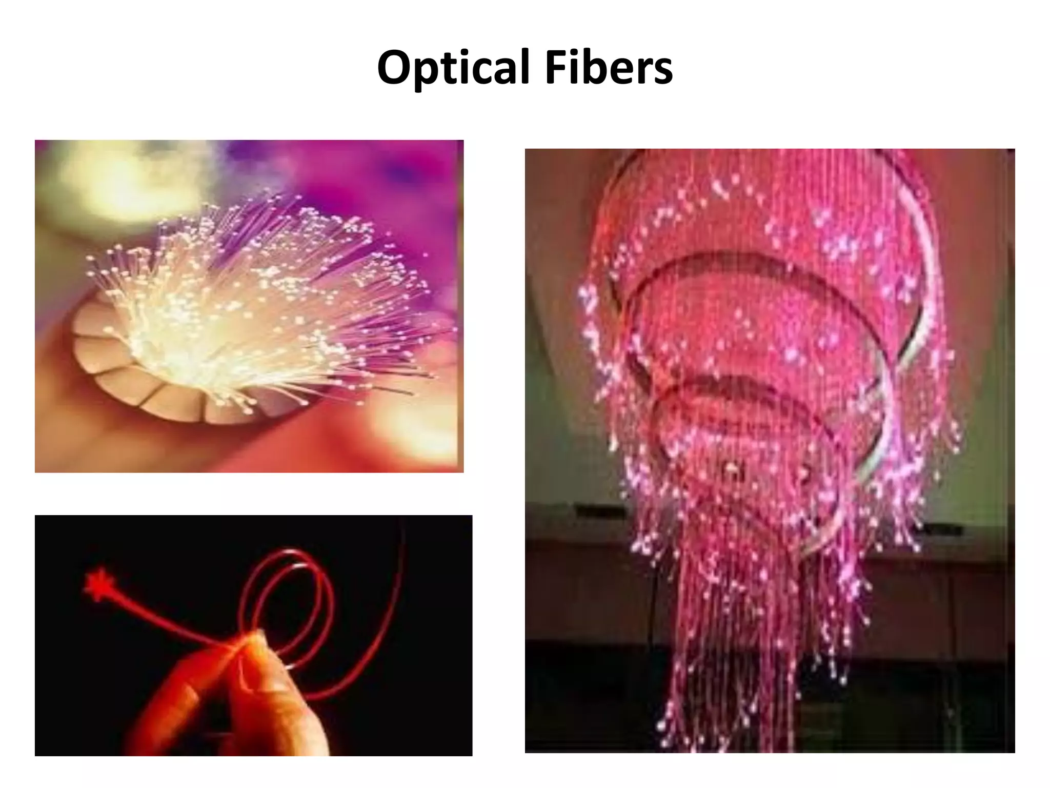
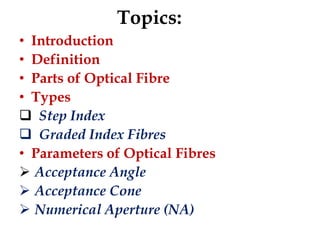
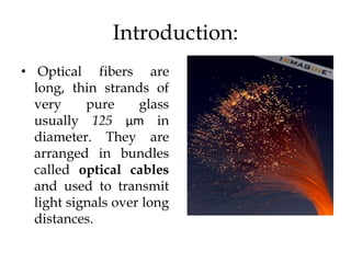
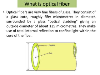
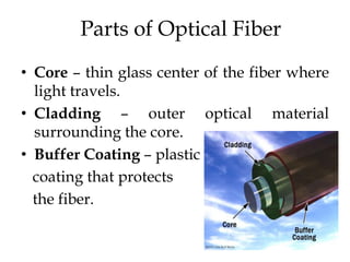
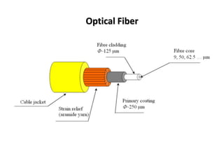
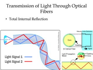
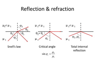
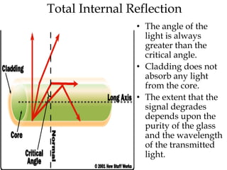
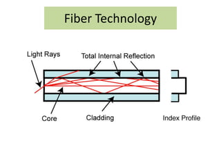
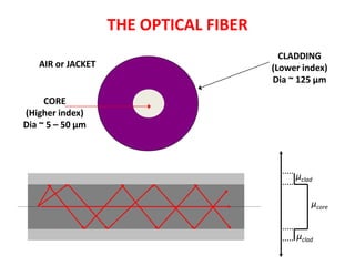
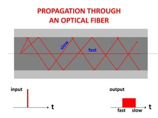
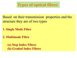
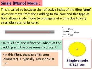
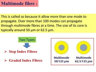
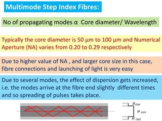
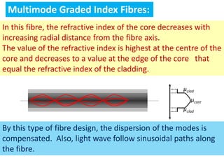
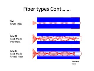
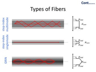
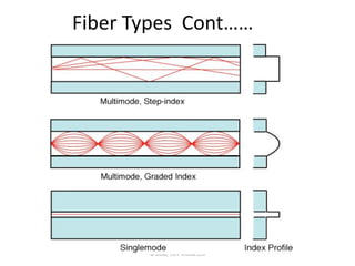
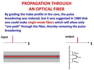
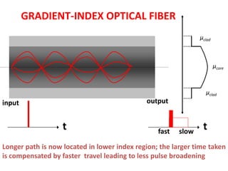
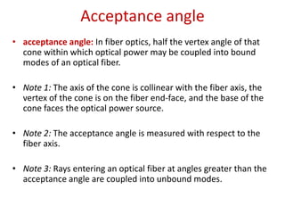
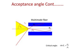
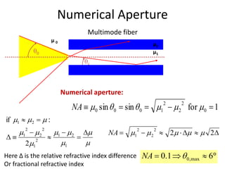
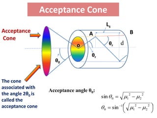
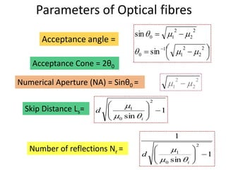
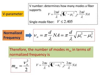
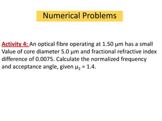
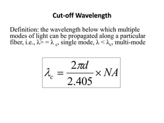
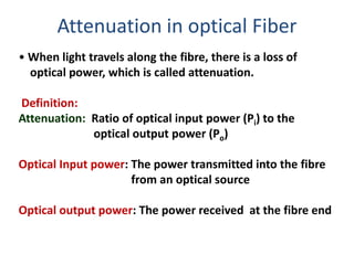
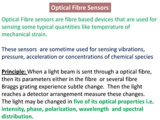
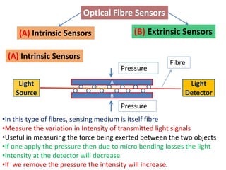
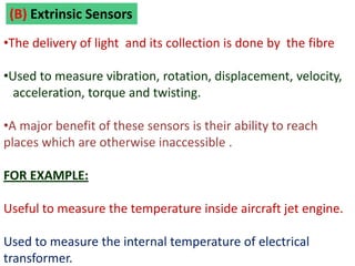
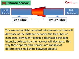
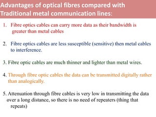
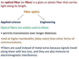
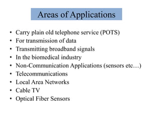
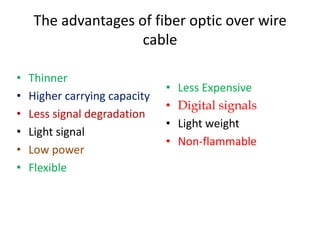
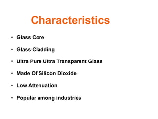
SlideShare a Scribd company logo
Optical Fibers
Topics:
• Introduction
• Definition
• Parts of Optical Fibre
• Types
 Step Index
 Graded Index Fibres
• Parameters of Optical Fibres
 Acceptance Angle
 Acceptance Cone
 Numerical Aperture (NA)
Cont…….
                 Topics:
• Normalized Frequency
• Number of Modes
• Attenuation in Optical Fibres
• Dispersion
1. Intermodal Dispersion
2. Intramodal Dispersion
• Applications
1. Optical fibres in Communication
2. Sensors
Introduction:
• Optical fibers are
  long, thin strands of
  very     pure     glass
  usually 125 µm in
  diameter. They are
  arranged in bundles
  called optical cables
  and used to transmit
  light signals over long
  distances.
What is optical fiber
• Optical fibers are very fine fibers of glass. They consist of
  a glass core, roughly fifty micrometres in diameter,
  surrounded by a glass "optical cladding" giving an
  outside diameter of about 125 micrometres. They make
  use of total internal reflection to confine light within the
  core of the fiber.
Parts of Optical Fiber
• Core – thin glass center of the fiber where
  light travels.
• Cladding – outer optical material
  surrounding the core.
• Buffer Coating – plastic
  coating that protects
  the fiber.
Optical Fiber
Transmission of Light Through Optical
                Fibers
• Total Internal Reflection
Reflection & refraction

μ2< μ 1            2           μ 2< μ 1              μ 2< μ 1
                           2
          1            1         1=   c
                                                            1> c
μ1            1                μ1           c        μ1

     Snell’s law                    Critical angle        Total internal
                                                            reflection
                                                2
                                      sin   c
                                                1
Total Internal Reflection
                • The angle of the
                  light is always
                  greater than the
                  critical angle.
                • Cladding does not
                  absorb any light
                  from the core.
                • The extent that the
                  signal degrades
                  depends upon the
                  purity of the glass
                  and the wavelength
                  of the transmitted
                  light.
Fiber Technology
THE OPTICAL FIBER
                                         CLADDING
   AIR or JACKET                       (Lower index)
                                       Dia ~ 125 µm

     CORE
(Higher index)
Dia ~ 5 – 50 µm


                                            μclad

                                                μcore


                                            μclad
PROPAGATION THROUGH
           AN OPTICAL FIBER


                   fast


input                     output


           t                 fast   slow
                                           t
Types of optical fibres

Based on their transmission properties and the
structure they are of two types

1. Single Mode Fibre

2. Multimode Fibre

   (a) Step Index Fibres
   (b) Graded Index Fibres
Single (Mono) Mode :
This is called so because the refractive index of the fibre ‘step’
up as we move from the cladding to the core and this type of
fibre allows single mode to propagate at a time due to very
small diameter of its core.
                                                 μ clad
                                                          μcore
                                                 μ clad


 In this fibre, the refractive indices of the
cladding and the core remain constant

  In this fibre, the size of its core
 (diameter) is typically around 9-10
 μm.
Multimode fibre :

This is called so because it allow more than one mode to
propagate. Over more than 100 modes can propagate
through multimode fibres at a time. The size of its core is
typically around 50 μm or 62.5 μm.

            Two Types


   Step Index Fibres

   Graded Index Fibres
Multimode Step Index Fibres:
No of propagating modes α Core diameter/ Wavelength

Typically the core diameter is 50 μm to 100 μm and Numerical
Aperture (NA) varies from 0.20 to 0.29 respectively

Due to higher value of NA , and larger core size in this case,
fibre connections and launching of light is very easy
Due to several modes, the effect of dispersion gets increased,
i.e. the modes arrive at the fibre end slightly different times
and so spreading of pulses takes place.
                                                     μclad
                                                        μ core
                                                     μ clad
Multimode Graded Index Fibres:
In this fibre, the refractive index of the core decreases with
increasing radial distance from the fibre axis.
The value of the refractive index is highest at the centre of the
core and decreases to a value at the edge of the core that
equal the refractive index of the cladding.

                                                     μclad
                                                        μcore
                                                     μclad


By this type of fibre design, the dispersion of the modes is
compensated. Also, light wave follow sinusoidal paths along
the fibre.
The profile of the refractive index is nearly parabolic that
results in continual refocusing of the ray in the core, and
minimizing the model dispersion.
Standard graded index fibres typically have a core diameter of
50 μm or 62.5 μm and the cladding diameter of 125 μm.


  Advantage of Graded Index Fibre over Step Index Fibre


             Decrease in the modal dispersion
Advantage of Single Mode Fibre over Multi Mode Fibre

Lower signal loss and a higher information capacity or
 bandwidth than multimode fibres as the signal loss
 depends on the operational wavelength.

These fibres are capable of transferring higher amount of
  data due to low fibre dispersion.

 Single mode fibres are known as low loss fibres
Comparison
Fiber types Cont…….
SM
Single-Mode


MM-SI
Multi-Mode
Step Index


MM-GI
Multi-Mode
Graded Index

                                     refractive
                                     index
Cont…….
singlemode multimode
                         Types of Fibers
 step-index step-index


                                           μclad
                                              μcore
                                           μclad


                                           μclad
                                                   μcore
                                           μclad


                                           μclad
       GRIN


                                              μcore
                                           μclad
Fiber Types Cont……


       © 2006, VDV Works LLC
PROPAGATION THROUGH
                AN OPTICAL FIBER
  By grading the index profile in the core, the pulse
  broadening was reduced, but it was suggested in 1980 that
  one could make single-mode fibers which will allow only
  “one path” through the fiber, thereby removing the pulse
  broadening
input                                      output

                 t                                            t
                                                 μclad
                                                    μcore
                                                 μclad
GRADIENT-INDEX OPTICAL FIBER
                                                               μclad


                                                                       μcore


                                                                 μclad
input                                        output


                   t                             fast   slow
                                                                t
Longer path is now located in lower index region; the larger time taken
is compensated by faster travel leading to less pulse broadening
Acceptance angle
• acceptance angle: In fiber optics, half the vertex angle of that
  cone within which optical power may be coupled into bound
  modes of an optical fiber.

• Note 1: The axis of the cone is collinear with the fiber axis, the
  vertex of the cone is on the fiber end-face, and the base of the
  cone faces the optical power source.

• Note 2: The acceptance angle is measured with respect to the
  fiber axis.

• Note 3: Rays entering an optical fiber at angles greater than the
  acceptance angle are coupled into unbound modes.
Acceptance angle Cont………


             Multimode fiber
        n0
        n0    μ2
    0                          μ1
               c


                                                      2
                          Critical angle:   sin   c
                                                      1
Numerical Aperture
                                                        Multimode fiber
                                     μ0
                                     n0                                                        μ2
                     0                                                                         μ1
                                                        c


                                              Numerical aperture:
                                                                                                          2           2
                                                   NA       0   sin    0   sin           0            1           2       for       0       1
if   1           2               :
             2               2                                                       2            2
         1               2                1        2                  NA         1            2               2                         2
                     2
             2   1                             1

Here Δ is the relative refractive index difference                                           NA 0.1                       0 , max       6
Or fractional refractive index
Acceptance Cone
                                                 Ls
Acceptance                            A                             B
Cone
                                 o                θr        d
                                       θr
                       θ0


The cone
associated with
                     Acceptance angle θ0:
the angle 2θ0 is                                                    2               2
                                            sin       0         1               2
called the
acceptance cone                              0        sin   1
                                                                        1
                                                                            2
                                                                                        2
                                                                                            2
Parameters of Optical fibres
                                                                2                   2
                                     sin
      Acceptance angle =                      0             1                   2

                                                    1                   2                       2
                                      0       sin                   1                       2

    Acceptance Cone = 2θ0
                                                                2                       2
Numerical Aperture (NA) = Sinθ0 =                           1                       2

                                              2

  Skip Distance Ls=   d          1
                                                    1
                            0   sin       i


                                                                1
                                                                                        2
   Number of reflections Nr =                                   1
                                          d                                                         1
                                                        0   sin             i
Numerical Problems
Activity 1: The refractive indices for core and cladding for a
step index fibre are 1.52 and 1.41 respectively
Caculate (1) Critical angle (2) Numerical Aperture
(3) The maximum incidence angle


 Hints: Given Here =μ1 = μcore = 1.52, and μ2 = μclad = 1.41
                                                                    Ans = 68.060
               Critical angle θc =   sin-1      (μ2/ μ1)
                                            2           2           Ans = 0.568
         Numerical Aperture             1           2

                                                                2         2
 Maximum incidence angle (θ0)=                    sin   1
                                                            1         2

                                                                              Ans θ0 = 34.60
Numerical Problems
Activity 2: A light ray enters from air to a fibre. The refractive
Index of air is 1.0. The fibre has refractive index of core is
equal to 1.5 and that of cladding is 1.48. Find the critical
Angle, the fractional refractive index, the acceptance angle and
Numerical aperture.
Hints: Given Here =μ0 = μair = 1.0; μ1 = μcore = 1.5, and μ2 = μclad
= 1.48
              Critical angle θc = sin-1 (μ2/ μ1) Ans: θc = 80.630
                                      1               2
 Fractional Refractive index                                                  = 1.33% of light
                                                  1
                                                                                  Ans = 0.568
                                              2                   2
        Numerical Aperture                1                   2

                                      1                   2               2
Acceptance angle (θ0) =         sin                   1               2          Ans θ0 = 14.130
Numerical Problems
Activity 3: Calculate the refractive indices of the core and
cladding material of fibre from the following data:
NA = 0.22, Δμr = 0.012 and
                                                   core              cladding
                                   r
                                                                  core

Hints:
 Fractional Refractive index           1             2

                                               1


      Numerical Aperture                   2                  2
                                       1                  2


          Ans : μ1= 1.424 = μcore and μ2= 0.988 μ1 = 1.41 = μcladding
Allowed Modes and Normalized Frequency
                                                                       2
Maximum Number of modes that                       1       d
propagate successively in the fibre      mm                    NA
                                                   2
                                     d
                           mm

 Hence, number of possible modes will be larger for higher ratio d/λ

    For multimode fibres mm > 2               OR
                                                       d       2
    For single mode fibres mm < 2                              NA
As is evident the parameter mm decides the number of possible
modes since this parameter depends on core diameter d and
the numerical aperture NA. Therefore, the number of allowed
modes would be different for fibres of different core diameters.
V number: determines how many modes a fiber
                  supports
                                  2 d             2 d
V-parameter                   V          1
                                           2
                                             2
                                               2
                                                      NA

                  Single-mode fiber: V            2.405

Normalized                      d                    d        2   2
Frequency             n             NA                        1   2


   Therefore, the number of modes mm in terms of
   normalized frequency is
              2
              n           2 a        2        2    2 a
    mm                V         n1       n2              NA
              2
Numerical Problems


Activity 4: An optical fibre operating at 1.50 μm has a small
Value of core diameter 5.0 μm and fractional refractive index
difference of 0.0075. Calculate the normalized frequency
and acceptance angle, given μ2 = 1.4.
Cut-off Wavelength
Definition: the wavelength below which multiple
modes of light can be propagated along a particular
fiber, i.e., λ> = λ c, single mode, λ < λc, multi-mode


                       2 d
                c           NA
                      2.405
Attenuation in optical Fiber
• When light travels along the fibre, there is a loss of
  optical power, which is called attenuation.

Definition:
Attenuation: Ratio of optical input power (Pi) to the
             optical output power (Po)

Optical Input power: The power transmitted into the fibre
                     from an optical source

Optical output power: The power received at the fibre end
Fiber Attenuation Cont……..
This relation defines the signal attenuation or absorption
coefficient in terms of length L of the fibre:

                           10       P
                              log 10 i
                            L       P0

       Length L of the fibre is expressed in kilometers
       Here, the unit of Attenuation is decibels/kilometer i.e. dB/km.

     The main causes of attenuation in optical fibre are:
     (a)Absorption
     (b)Scattering
     (c)Bending losses
     Each mechanism of loss is influenced by the properties of fibre
     Material and fibre structure.
Fiber Attenuation Cont……..
Absorption losses over a length L of fiber can be described
by the usual exponential law for light intensity (or irradiance) I

                                       L
                       I      I 0e
Where I0 is the initial intensity or the irradiance of the light.
The attenuation profile is shown in figure which shows the amount of
Attenuation is also wavelength dependent.

                                                 In the figure, two
                                                 absorption peaks at
                                                 1.25 μm and 1.4 μm
                                                 are observed which are
                                                 respectively due to the
                                                  peculiarities of the
                                                 single mode fibre and
                                                 the traces of water
                                                 remaining in the fibre as
                                                 an impurity.

                                              For commercially available fibers

                                              Loss   0.5 dB/km @ 1310 nm
                                                     0.25 dB/km @ 1550 nm
Dispersion
• A pulse of light sent into a fibre broaden in time as it
  propagate through the fibre. This phenomenon is
  known as pulse dispersion.

• Intermodal Dispersion: Different rays take different
  times to propagate through a given length of the fibre.
  Or Different modes travel with different speeds

• Intarmodal dispersion: Any given source emits over a
  range of wavelength and because of the intrinsic
  property of the material of the fibre, different
  wavelength takes different amount of time to
  propagate along the same path.
Dispersion in Fiber Optics


• Dispersion occurs when photons from the same light
  pulse take slight different paths along the optical fiber.
  Because some paths will be longer or shorter than other
  paths the photons will arrive at different times thus
  smearing the shape of the pulse.
• Over long distances, one pulse may merge with another pulse.
  When this happens, the receiving device will not be able to
  distinguish between pulses.

The dispersive effects in a single mode fibre are much smaller than a
multimode fibre. Due to dispersion, optical pulses in optical fibres
spread and hence the signal spread over long distances.
Pulse Dispersion in Optical Fibre


In optics, dispersion is the phenomenon in which the
phase velocity of a wave depends on its frequency.
 Such medium is called a dispersive medium.
Intermodal Dispersion
Different rays take
different times to
propagate through a given
length of the fibre.
In the language of wave
optics, this is known as
intermodal dispersion
because it arises due to
the different modes
travelling with different
speeds.
Intramodal Dispersion

Any given light source emits
over a range of wavelength
and because of the intrinsic
property of the material of the
fibre, different wavelengths
takes different amounts of
time to propagate along the
same path. This is known as
material dispersion or
intramodel dispersion
Cont……..
There are several factors that cause dispersion in
optical fibres.
 For Example:
(1) In multimode fibres different axial speeds of different
transverse modes cause intermodal dispersion that limits
the performance of the fibre.
(2) In singe mode fibres, though intermodal dispersion
is eliminated, chromatic dispersion occures because of
The slight variation in the index of the glass with the
wavelength of the light.
Dispersion limits the bandwidth of the fibre because the
 spreading optical pulses limit the rate that pulses can
follow one another on the fibre and still remain
distinguishable at the receiver.
Chromatic Dispersion
For example, when white light passes through a prism some of the
wavelengths of light bend more because their refractive index is
higher, i.e. they travel slower This is what gives us the "Spectrum" of
white light. The "red' and "orange" light travel slowest and so are bent
most while the "violet" and "blue" travel fastest and so are bent less. All
the other colours lie in between


                 Figure -The Dispersion of White Light
Massage           Modulator        Optical
 Input          (Transmitter)      Source


                                              Optical
          Fibre Optics Communication           Fibre


                     Demodulator        Optical
  Destination         (Receiver)       detector
A TYPICAL OPTICAL
         COMMUNICATION SYSTEM
  Electrical Signal      Electrical Signal
                                             Optical Fiber

       Optical Source      External
        LED or Laser       Modulator

                                                       Connector/
                             Optical
                                                       Splice
  Optical Detector
    PIN Diode               Amplifier


Processing electronics
Optical Fibre Sensors
Optical Fibre sensors are fibre based devices that are used for
sensing some typical quantities like temperature of
mechanical strain.

These sensors are sometime used for sensing vibrations,
pressure, acceleration or concentrations of chemical species

Principle: When a light beam is sent through a optical fibre,
then its parameters either in the fibre or several fibre
Braggs grating experience subtle change. Then the light
reaches a detector arrangement measure these changes.
The light may be changed in five of its optical properties i.e.
intensity, phase, polarization, wavelength and spectral
distribution.
Optical Fibre Sensors

     (A) Intrinsic Sensors                (B) Extrinsic Sensors

 (A) Intrinsic Sensors
                                                      Fibre
                                      Pressure

     Light                        A                        Light
    Source                        B                       Detector
                                      Pressure
•In this type of fibres, sensing medium is itself fibre
•Measure the variation in Intensity of transmitted light signals
•Useful in measuring the force being exerted between the two objects
•If one apply the pressure then due to micro bending losses the light
•intensity at the detector will decrease
•If we remove the pressure the intensity will increase.
(B) Extrinsic Sensors
•The delivery of light and its collection is done by the fibre

•Used to measure vibration, rotation, displacement, velocity,
  acceleration, torque and twisting.

•A major benefit of these sensors is their ability to reach
places which are otherwise inaccessible .

FOR EXAMPLE:

Useful to measure the temperature inside aircraft jet engine.

Used to measure the internal temperature of electrical
transformer.
(B) Extrinsic Sensors                              Cont……..

 Light                                                Light
Source                                               Detector

         Feed Fibre          l
                                      Return Fibre


   The amount of light launched into the return fibre will
   decrease as the distance between the two fibers is
   increased. However if length is decreased the light
   intensity collected by the receiver will decrease. This
   way these optical fibre sensors are capable of
   determining small shifts between objects.
Advantages of optical fibres compared with
Traditional metal communication lines:
1. Fibre optics cables can carry more data as their bandwidth is
   greater than metal cables

2. Fibre optics cables are less susceptible (sensitive) then metal cables
   to interference.

3. Fibre optic cables are much thinner and lighter than metal wires.

4. Through fibre optic cables the data can be transmitted digitally rather
   than analogically.

5. Attenuation through fibre cables is very low in transmitting the data
  over a long distance, so there is no need of repeaters (thing that
    repeats)
An optical fiber (or fibre) is a glass or plastic fiber that carries
light along its length.
                    Fiber optics


Applied science                    Engineering
Optical fibers are widely used as these
• permits transmission over longer distances
•and at higher bandwidths (data rates) than other forms of
communications.
•Fibers are used instead of metal wires because signals travel
along them with less loss, and they are also immune to
electromagnetic interference.
Areas of Applications
•   Carry plain old telephone service (POTS)
•   For transmission of data
•   Transmitting broadband signals
•   In the biomedical industry
•   Non-Communication Applications (sensors etc…)
•   Telecommunications
•   Local Area Networks
•   Cable TV
•   Optical Fiber Sensors
The advantages of fiber optic over wire
                    cable

•   Thinner
                               •   Less Expensive
•   Higher carrying capacity
                               •   Digital signals
•   Less signal degradation
                               •   Light weight
•   Light signal
                               •   Non-flammable
•   Low power
•   Flexible
DISADVANTAGES OF OPTICAL FIBERS…

 The terminating equipment is still costly as compared to copper
  equipment.

1. IT has to be handled carefully.

2. Optical fiber is more expensive per meter than copper

  Communication is not totally in optical domain, so repeated
   electric –optical – electrical conversion is needed.

1. Tapping is not possible. Specialized equipment is needed to tap a
   fiber.

1. Optical fiber splicing (joining by interweaving strands) is a
   specialized technique and needs expertly trained manpower.
DISADVANTAGES OF OPTICAL FIBERS…

1. The splicing (joining by interweaving strands) and testing
   equipments are very expensive as compared to copper
   equipments.

2. Optical fiber can not be join together as easily as copper cable. It
   requires training and expensive splicing (joining by interweaving
   strands) and measurement equipment.
A Light Sources


LED (Light emitting diode)    ILD (injection laser diode)
Optical source
TRANSMITTER


                             FIBER


                             Performance
  +           –              Modulation speed
                             Fiber-coupled power
Light Emitting Diode (LED)


–       +
            Typical performance data
            Power in MM-fiber:             100    W
            Power in SM-fiber:             1      W
            Direct Modulation Bandwidth:   100   MHz
Laser


Typical performance

Power (in fiber):               5-10    mW
Max:                            100-300 mW
Direct Modulation Bandwidth:    1-10    GHz
• Telecommunications

• Internet Access

• Cable and Satellite
  Television

• Decorative Light Source
Characteristics
• Glass Core

• Glass Cladding

• Ultra Pure Ultra Transparent Glass

• Made Of Silicon Dioxide

• Low Attenuation

• Popular among industries
Towers
Buildings
Towers
Installation of Antennas
Thank You
Any Questions or Comments?

More Related Content

What's hot

Optical fiber communication
Optical fiber          communicationOptical fiber          communication
Optical fiber communication
anitha bolleddu
 
Optical fiber communiction system
Optical fiber communiction systemOptical fiber communiction system
Optical fiber communiction systemrahulohlan14
 
Fiber Optics Course
Fiber Optics Course Fiber Optics Course
Fiber Optics Course
Ahmed OM
 
Optical fiber communication-Presented by Kiran Devkota
Optical fiber communication-Presented by Kiran DevkotaOptical fiber communication-Presented by Kiran Devkota
Optical fiber communication-Presented by Kiran Devkota
Sujit Jha
 
Evolution of Optical Fibers
Evolution of Optical FibersEvolution of Optical Fibers
Evolution of Optical Fibers
Sourabh Roy
 
Optical fiber communication Part 1 Optical Fiber Fundamentals
Optical fiber communication Part 1 Optical Fiber FundamentalsOptical fiber communication Part 1 Optical Fiber Fundamentals
Optical fiber communication Part 1 Optical Fiber Fundamentals
Madhumita Tamhane
 
Optical fiber
Optical fiberOptical fiber
Optical fiber
sandhya singh
 
Fibre optics
Fibre opticsFibre optics
Fibre optics
Usman Namadi
 
optical fiber ppt
optical fiber ppt optical fiber ppt
optical fiber ppt
RUSHIT PATEL
 
optical fibre ppt for download visit http://nowcracktheworld.blogspot.in/
optical fibre  ppt for download visit http://nowcracktheworld.blogspot.in/optical fibre  ppt for download visit http://nowcracktheworld.blogspot.in/
optical fibre ppt for download visit http://nowcracktheworld.blogspot.in/
Ram Niwas Bajiya
 
OPTICAL FIBER COMMUNICATION UNIT-1
OPTICAL FIBER COMMUNICATION UNIT-1OPTICAL FIBER COMMUNICATION UNIT-1
OPTICAL FIBER COMMUNICATION UNIT-1
Asif Iqbal
 
Optical fibres
Optical fibresOptical fibres
Optical fibres
Vishnu Kudumula
 
Introduction to optical fiber
Introduction to optical fiberIntroduction to optical fiber
Introduction to optical fiber
sindhum54321
 
Dispersion in optical fibers
Dispersion in optical fibersDispersion in optical fibers
Dispersion in optical fibers
CKSunith1
 
physics b.tech. 1st sem fibre optics,u 4
physics b.tech. 1st sem fibre optics,u 4physics b.tech. 1st sem fibre optics,u 4
physics b.tech. 1st sem fibre optics,u 4Kumar
 
Non linear effects in optical fibers
Non linear effects in optical fibersNon linear effects in optical fibers
Non linear effects in optical fibers
CKSunith1
 
Optical fiber Communication
Optical fiber Communication Optical fiber Communication
Optical fiber Communication
Saurabh Kumar
 
Optical fiber
Optical fiberOptical fiber
Optical fiber
vishakha trivedi
 
02-Fundamentals of Optical Fiber Waveguides-I.pptx
02-Fundamentals of Optical Fiber Waveguides-I.pptx02-Fundamentals of Optical Fiber Waveguides-I.pptx
02-Fundamentals of Optical Fiber Waveguides-I.pptx
AkliluAyele3
 
Chapter 2c
Chapter 2cChapter 2c
Chapter 2c
Gabriel O'Brien
 

What's hot (20)

Optical fiber communication
Optical fiber          communicationOptical fiber          communication
Optical fiber communication
 
Optical fiber communiction system
Optical fiber communiction systemOptical fiber communiction system
Optical fiber communiction system
 
Fiber Optics Course
Fiber Optics Course Fiber Optics Course
Fiber Optics Course
 
Optical fiber communication-Presented by Kiran Devkota
Optical fiber communication-Presented by Kiran DevkotaOptical fiber communication-Presented by Kiran Devkota
Optical fiber communication-Presented by Kiran Devkota
 
Evolution of Optical Fibers
Evolution of Optical FibersEvolution of Optical Fibers
Evolution of Optical Fibers
 
Optical fiber communication Part 1 Optical Fiber Fundamentals
Optical fiber communication Part 1 Optical Fiber FundamentalsOptical fiber communication Part 1 Optical Fiber Fundamentals
Optical fiber communication Part 1 Optical Fiber Fundamentals
 
Optical fiber
Optical fiberOptical fiber
Optical fiber
 
Fibre optics
Fibre opticsFibre optics
Fibre optics
 
optical fiber ppt
optical fiber ppt optical fiber ppt
optical fiber ppt
 
optical fibre ppt for download visit http://nowcracktheworld.blogspot.in/
optical fibre  ppt for download visit http://nowcracktheworld.blogspot.in/optical fibre  ppt for download visit http://nowcracktheworld.blogspot.in/
optical fibre ppt for download visit http://nowcracktheworld.blogspot.in/
 
OPTICAL FIBER COMMUNICATION UNIT-1
OPTICAL FIBER COMMUNICATION UNIT-1OPTICAL FIBER COMMUNICATION UNIT-1
OPTICAL FIBER COMMUNICATION UNIT-1
 
Optical fibres
Optical fibresOptical fibres
Optical fibres
 
Introduction to optical fiber
Introduction to optical fiberIntroduction to optical fiber
Introduction to optical fiber
 
Dispersion in optical fibers
Dispersion in optical fibersDispersion in optical fibers
Dispersion in optical fibers
 
physics b.tech. 1st sem fibre optics,u 4
physics b.tech. 1st sem fibre optics,u 4physics b.tech. 1st sem fibre optics,u 4
physics b.tech. 1st sem fibre optics,u 4
 
Non linear effects in optical fibers
Non linear effects in optical fibersNon linear effects in optical fibers
Non linear effects in optical fibers
 
Optical fiber Communication
Optical fiber Communication Optical fiber Communication
Optical fiber Communication
 
Optical fiber
Optical fiberOptical fiber
Optical fiber
 
02-Fundamentals of Optical Fiber Waveguides-I.pptx
02-Fundamentals of Optical Fiber Waveguides-I.pptx02-Fundamentals of Optical Fiber Waveguides-I.pptx
02-Fundamentals of Optical Fiber Waveguides-I.pptx
 
Chapter 2c
Chapter 2cChapter 2c
Chapter 2c
 

Viewers also liked

application of fibre optics in communication
application of fibre optics in communicationapplication of fibre optics in communication
application of fibre optics in communication
Rimmi07
 
OPTICAL FIBER COMMUNICATION PPT
OPTICAL FIBER COMMUNICATION PPTOPTICAL FIBER COMMUNICATION PPT
OPTICAL FIBER COMMUNICATION PPT
Er. Satyendra Vishwakarma
 
Optical fibres
Optical fibresOptical fibres
Optical fibres
Clement Chia
 
Chapter 2b
Chapter 2bChapter 2b
Chapter 2b
Gabriel O'Brien
 
Presentation about Fiber Optics
Presentation about Fiber OpticsPresentation about Fiber Optics
Presentation about Fiber Optics
Abidullah Zarghoon
 
150860106054 150860106004 150860106045_150860106070_150860106010
150860106054 150860106004 150860106045_150860106070_150860106010150860106054 150860106004 150860106045_150860106070_150860106010
150860106054 150860106004 150860106045_150860106070_150860106010
Riya2001998
 
Actividad 0.0
Actividad 0.0Actividad 0.0
Actividad 0.0
Monse Castillo
 
Hamza Al-Jaghbeer - Training Report Presentation - Yarmouk Univ. - Hijjawi
Hamza Al-Jaghbeer - Training Report Presentation - Yarmouk Univ. - HijjawiHamza Al-Jaghbeer - Training Report Presentation - Yarmouk Univ. - Hijjawi
Hamza Al-Jaghbeer - Training Report Presentation - Yarmouk Univ. - HijjawiHamza Al-Jaghbeer
 
Fiber Optics Lab Experiments (EDWDM KIT,EDCOM KIT, EDLASE KIT, EDAMP KIT, L...
Fiber Optics Lab  Experiments (EDWDM KIT,EDCOM KIT, EDLASE KIT, EDAMP KIT,  L...Fiber Optics Lab  Experiments (EDWDM KIT,EDCOM KIT, EDLASE KIT, EDAMP KIT,  L...
Fiber Optics Lab Experiments (EDWDM KIT,EDCOM KIT, EDLASE KIT, EDAMP KIT, L...megha agrawal
 
Desinging dsp (0, 1) acceptance sampling plans based on truncated life tests ...
Desinging dsp (0, 1) acceptance sampling plans based on truncated life tests ...Desinging dsp (0, 1) acceptance sampling plans based on truncated life tests ...
Desinging dsp (0, 1) acceptance sampling plans based on truncated life tests ...
eSAT Journals
 
waveguiding in optical fibers
waveguiding in optical fiberswaveguiding in optical fibers
waveguiding in optical fibers
Shristi Gupta
 
How to Select the Best Refractive Index for Particle Size Analysis
How to Select the Best Refractive Index for Particle Size AnalysisHow to Select the Best Refractive Index for Particle Size Analysis
How to Select the Best Refractive Index for Particle Size Analysis
HORIBA Particle
 
experiment to determine the numerical aperture of an optical fibre..
experiment to determine the numerical aperture  of an optical fibre..experiment to determine the numerical aperture  of an optical fibre..
experiment to determine the numerical aperture of an optical fibre..
sourabhrana21
 
Lect12 photodiode detectors
Lect12 photodiode detectorsLect12 photodiode detectors
Lect12 photodiode detectors
wtyru1989
 
Chapter 2a
Chapter 2aChapter 2a
Chapter 2a
Gabriel O'Brien
 
PM [D02] de Broglie deriving the Equation
PM [D02] de Broglie deriving the EquationPM [D02] de Broglie deriving the Equation
PM [D02] de Broglie deriving the Equation
Stephen Kwong
 

Viewers also liked (20)

application of fibre optics in communication
application of fibre optics in communicationapplication of fibre optics in communication
application of fibre optics in communication
 
OPTICAL FIBER COMMUNICATION PPT
OPTICAL FIBER COMMUNICATION PPTOPTICAL FIBER COMMUNICATION PPT
OPTICAL FIBER COMMUNICATION PPT
 
Optical fibres
Optical fibresOptical fibres
Optical fibres
 
Chapter 2b
Chapter 2bChapter 2b
Chapter 2b
 
FOT_MEng2004_FEUP
FOT_MEng2004_FEUPFOT_MEng2004_FEUP
FOT_MEng2004_FEUP
 
Losses in optical fiber
Losses in optical fiberLosses in optical fiber
Losses in optical fiber
 
Presentation about Fiber Optics
Presentation about Fiber OpticsPresentation about Fiber Optics
Presentation about Fiber Optics
 
150860106054 150860106004 150860106045_150860106070_150860106010
150860106054 150860106004 150860106045_150860106070_150860106010150860106054 150860106004 150860106045_150860106070_150860106010
150860106054 150860106004 150860106045_150860106070_150860106010
 
Kushilov Chowdhury
Kushilov ChowdhuryKushilov Chowdhury
Kushilov Chowdhury
 
Actividad 0.0
Actividad 0.0Actividad 0.0
Actividad 0.0
 
Mwe lab manual
Mwe lab manualMwe lab manual
Mwe lab manual
 
Hamza Al-Jaghbeer - Training Report Presentation - Yarmouk Univ. - Hijjawi
Hamza Al-Jaghbeer - Training Report Presentation - Yarmouk Univ. - HijjawiHamza Al-Jaghbeer - Training Report Presentation - Yarmouk Univ. - Hijjawi
Hamza Al-Jaghbeer - Training Report Presentation - Yarmouk Univ. - Hijjawi
 
Fiber Optics Lab Experiments (EDWDM KIT,EDCOM KIT, EDLASE KIT, EDAMP KIT, L...
Fiber Optics Lab  Experiments (EDWDM KIT,EDCOM KIT, EDLASE KIT, EDAMP KIT,  L...Fiber Optics Lab  Experiments (EDWDM KIT,EDCOM KIT, EDLASE KIT, EDAMP KIT,  L...
Fiber Optics Lab Experiments (EDWDM KIT,EDCOM KIT, EDLASE KIT, EDAMP KIT, L...
 
Desinging dsp (0, 1) acceptance sampling plans based on truncated life tests ...
Desinging dsp (0, 1) acceptance sampling plans based on truncated life tests ...Desinging dsp (0, 1) acceptance sampling plans based on truncated life tests ...
Desinging dsp (0, 1) acceptance sampling plans based on truncated life tests ...
 
waveguiding in optical fibers
waveguiding in optical fiberswaveguiding in optical fibers
waveguiding in optical fibers
 
How to Select the Best Refractive Index for Particle Size Analysis
How to Select the Best Refractive Index for Particle Size AnalysisHow to Select the Best Refractive Index for Particle Size Analysis
How to Select the Best Refractive Index for Particle Size Analysis
 
experiment to determine the numerical aperture of an optical fibre..
experiment to determine the numerical aperture  of an optical fibre..experiment to determine the numerical aperture  of an optical fibre..
experiment to determine the numerical aperture of an optical fibre..
 
Lect12 photodiode detectors
Lect12 photodiode detectorsLect12 photodiode detectors
Lect12 photodiode detectors
 
Chapter 2a
Chapter 2aChapter 2a
Chapter 2a
 
PM [D02] de Broglie deriving the Equation
PM [D02] de Broglie deriving the EquationPM [D02] de Broglie deriving the Equation
PM [D02] de Broglie deriving the Equation
 

Similar to 6796.optical fibres

Fibre opitcs
Fibre opitcsFibre opitcs
Optical fibre cable
Optical fibre cableOptical fibre cable
Optical fibre cable
Saroj Kumar Gochhayat
 
Optical fibres by Dr Praful D Shirbhate
Optical fibres by Dr Praful D ShirbhateOptical fibres by Dr Praful D Shirbhate
Optical fibres by Dr Praful D Shirbhate
Dr Praful D Shirbhate
 
Physics presentation(step index and graded index)
Physics presentation(step index and graded index)Physics presentation(step index and graded index)
Physics presentation(step index and graded index)
Ritesh Goyal
 
Fiber optics
Fiber opticsFiber optics
Fiber optics
Maaz ul haq
 
fiber_optics_1[1].pptx
fiber_optics_1[1].pptxfiber_optics_1[1].pptx
fiber_optics_1[1].pptx
Urus2
 
Fiber-optics-part-I.pdf
Fiber-optics-part-I.pdfFiber-optics-part-I.pdf
Fiber-optics-part-I.pdf
LuckyKaushik7
 
Ep notes
Ep notesEp notes
Ep notes
Abhi Hirpara
 
UNIT-III-OPTICAL COMMUNICATION
UNIT-III-OPTICAL COMMUNICATIONUNIT-III-OPTICAL COMMUNICATION
UNIT-III-OPTICAL COMMUNICATION
excelmeape
 
optical-fiber-presentation
optical-fiber-presentationoptical-fiber-presentation
optical-fiber-presentation
ATTO RATHORE
 
Assignment1 network media
Assignment1 network mediaAssignment1 network media
Assignment1 network media
Kokila Hettiarachchi
 
Optical fibers
Optical fibers Optical fibers
Optical fibers
SarvamangalaMaski
 
Optical fiber
Optical fiberOptical fiber
Optical fiber
Pradhan Rishi Sharma
 
Optical fiber communication system Important paper
Optical fiber communication system Important paper Optical fiber communication system Important paper
Optical fiber communication system Important paper
Dawood Aqlan
 
Fibre optics10032020
Fibre optics10032020Fibre optics10032020
Fibre optics10032020
Ravindra Bagade
 
Gandhinagar institute of technology optical fiber
Gandhinagar institute of technology optical fiberGandhinagar institute of technology optical fiber
Gandhinagar institute of technology optical fiber
nilnildarji
 
Fiber optics
Fiber optics Fiber optics
Fiber optics
ARVIND KANWATE
 
Macro Bending Losses in Single Mode Step Index Fiber
Macro Bending Losses in Single Mode Step Index FiberMacro Bending Losses in Single Mode Step Index Fiber
Opto electronics by er. sanyam s. saini me (reg) 2012-14
Opto electronics  by  er. sanyam s. saini  me  (reg) 2012-14Opto electronics  by  er. sanyam s. saini  me  (reg) 2012-14
Opto electronics by er. sanyam s. saini me (reg) 2012-14Sanyam Singh
 
Optical fibercommunictionsystem
Optical fibercommunictionsystemOptical fibercommunictionsystem
Optical fibercommunictionsystem
Cambridge institute of technology
 

Similar to 6796.optical fibres (20)

Fibre opitcs
Fibre opitcsFibre opitcs
Fibre opitcs
 
Optical fibre cable
Optical fibre cableOptical fibre cable
Optical fibre cable
 
Optical fibres by Dr Praful D Shirbhate
Optical fibres by Dr Praful D ShirbhateOptical fibres by Dr Praful D Shirbhate
Optical fibres by Dr Praful D Shirbhate
 
Physics presentation(step index and graded index)
Physics presentation(step index and graded index)Physics presentation(step index and graded index)
Physics presentation(step index and graded index)
 
Fiber optics
Fiber opticsFiber optics
Fiber optics
 
fiber_optics_1[1].pptx
fiber_optics_1[1].pptxfiber_optics_1[1].pptx
fiber_optics_1[1].pptx
 
Fiber-optics-part-I.pdf
Fiber-optics-part-I.pdfFiber-optics-part-I.pdf
Fiber-optics-part-I.pdf
 
Ep notes
Ep notesEp notes
Ep notes
 
UNIT-III-OPTICAL COMMUNICATION
UNIT-III-OPTICAL COMMUNICATIONUNIT-III-OPTICAL COMMUNICATION
UNIT-III-OPTICAL COMMUNICATION
 
optical-fiber-presentation
optical-fiber-presentationoptical-fiber-presentation
optical-fiber-presentation
 
Assignment1 network media
Assignment1 network mediaAssignment1 network media
Assignment1 network media
 
Optical fibers
Optical fibers Optical fibers
Optical fibers
 
Optical fiber
Optical fiberOptical fiber
Optical fiber
 
Optical fiber communication system Important paper
Optical fiber communication system Important paper Optical fiber communication system Important paper
Optical fiber communication system Important paper
 
Fibre optics10032020
Fibre optics10032020Fibre optics10032020
Fibre optics10032020
 
Gandhinagar institute of technology optical fiber
Gandhinagar institute of technology optical fiberGandhinagar institute of technology optical fiber
Gandhinagar institute of technology optical fiber
 
Fiber optics
Fiber optics Fiber optics
Fiber optics
 
Macro Bending Losses in Single Mode Step Index Fiber
Macro Bending Losses in Single Mode Step Index FiberMacro Bending Losses in Single Mode Step Index Fiber
Macro Bending Losses in Single Mode Step Index Fiber
 
Opto electronics by er. sanyam s. saini me (reg) 2012-14
Opto electronics  by  er. sanyam s. saini  me  (reg) 2012-14Opto electronics  by  er. sanyam s. saini  me  (reg) 2012-14
Opto electronics by er. sanyam s. saini me (reg) 2012-14
 
Optical fibercommunictionsystem
Optical fibercommunictionsystemOptical fibercommunictionsystem
Optical fibercommunictionsystem
 

Recently uploaded

Cracking the Workplace Discipline Code Main.pptx
Cracking the Workplace Discipline Code Main.pptxCracking the Workplace Discipline Code Main.pptx
Cracking the Workplace Discipline Code Main.pptx
Workforce Group
 
Putting the SPARK into Virtual Training.pptx
Putting the SPARK into Virtual Training.pptxPutting the SPARK into Virtual Training.pptx
Putting the SPARK into Virtual Training.pptx
Cynthia Clay
 
Project File Report BBA 6th semester.pdf
Project File Report BBA 6th semester.pdfProject File Report BBA 6th semester.pdf
Project File Report BBA 6th semester.pdf
RajPriye
 
Brand Analysis for an artist named Struan
Brand Analysis for an artist named StruanBrand Analysis for an artist named Struan
Brand Analysis for an artist named Struan
sarahvanessa51503
 
ENTREPRENEURSHIP TRAINING.ppt for graduating class (1).ppt
ENTREPRENEURSHIP TRAINING.ppt for graduating class (1).pptENTREPRENEURSHIP TRAINING.ppt for graduating class (1).ppt
ENTREPRENEURSHIP TRAINING.ppt for graduating class (1).ppt
zechu97
 
ikea_woodgreen_petscharity_cat-alogue_digital.pdf
ikea_woodgreen_petscharity_cat-alogue_digital.pdfikea_woodgreen_petscharity_cat-alogue_digital.pdf
ikea_woodgreen_petscharity_cat-alogue_digital.pdf
agatadrynko
 
RMD24 | Retail media: hoe zet je dit in als je geen AH of Unilever bent? Heid...
RMD24 | Retail media: hoe zet je dit in als je geen AH of Unilever bent? Heid...RMD24 | Retail media: hoe zet je dit in als je geen AH of Unilever bent? Heid...
RMD24 | Retail media: hoe zet je dit in als je geen AH of Unilever bent? Heid...
BBPMedia1
 
falcon-invoice-discounting-a-premier-platform-for-investors-in-india
falcon-invoice-discounting-a-premier-platform-for-investors-in-indiafalcon-invoice-discounting-a-premier-platform-for-investors-in-india
falcon-invoice-discounting-a-premier-platform-for-investors-in-india
Falcon Invoice Discounting
 
April 2024 Nostalgia Products Newsletter
April 2024 Nostalgia Products NewsletterApril 2024 Nostalgia Products Newsletter
April 2024 Nostalgia Products Newsletter
NathanBaughman3
 
Unveiling the Secrets How Does Generative AI Work.pdf
Unveiling the Secrets How Does Generative AI Work.pdfUnveiling the Secrets How Does Generative AI Work.pdf
Unveiling the Secrets How Does Generative AI Work.pdf
Sam H
 
FINAL PRESENTATION.pptx12143241324134134
FINAL PRESENTATION.pptx12143241324134134FINAL PRESENTATION.pptx12143241324134134
FINAL PRESENTATION.pptx12143241324134134
LR1709MUSIC
 
VAT Registration Outlined In UAE: Benefits and Requirements
VAT Registration Outlined In UAE: Benefits and RequirementsVAT Registration Outlined In UAE: Benefits and Requirements
VAT Registration Outlined In UAE: Benefits and Requirements
uae taxgpt
 
CADAVER AS OUR FIRST TEACHER anatomt in your.pptx
CADAVER AS OUR FIRST TEACHER anatomt in your.pptxCADAVER AS OUR FIRST TEACHER anatomt in your.pptx
CADAVER AS OUR FIRST TEACHER anatomt in your.pptx
fakeloginn69
 
What is the TDS Return Filing Due Date for FY 2024-25.pdf
What is the TDS Return Filing Due Date for FY 2024-25.pdfWhat is the TDS Return Filing Due Date for FY 2024-25.pdf
What is the TDS Return Filing Due Date for FY 2024-25.pdf
seoforlegalpillers
 
The Influence of Marketing Strategy and Market Competition on Business Perfor...
The Influence of Marketing Strategy and Market Competition on Business Perfor...The Influence of Marketing Strategy and Market Competition on Business Perfor...
The Influence of Marketing Strategy and Market Competition on Business Perfor...
Adam Smith
 
Attending a job Interview for B1 and B2 Englsih learners
Attending a job Interview for B1 and B2 Englsih learnersAttending a job Interview for B1 and B2 Englsih learners
Attending a job Interview for B1 and B2 Englsih learners
Erika906060
 
RMD24 | Debunking the non-endemic revenue myth Marvin Vacquier Droop | First ...
RMD24 | Debunking the non-endemic revenue myth Marvin Vacquier Droop | First ...RMD24 | Debunking the non-endemic revenue myth Marvin Vacquier Droop | First ...
RMD24 | Debunking the non-endemic revenue myth Marvin Vacquier Droop | First ...
BBPMedia1
 
What are the main advantages of using HR recruiter services.pdf
What are the main advantages of using HR recruiter services.pdfWhat are the main advantages of using HR recruiter services.pdf
What are the main advantages of using HR recruiter services.pdf
HumanResourceDimensi1
 
Maksym Vyshnivetskyi: PMO Quality Management (UA)
Maksym Vyshnivetskyi: PMO Quality Management (UA)Maksym Vyshnivetskyi: PMO Quality Management (UA)
Maksym Vyshnivetskyi: PMO Quality Management (UA)
Lviv Startup Club
 
Search Disrupted Google’s Leaked Documents Rock the SEO World.pdf
Search Disrupted Google’s Leaked Documents Rock the SEO World.pdfSearch Disrupted Google’s Leaked Documents Rock the SEO World.pdf
Search Disrupted Google’s Leaked Documents Rock the SEO World.pdf
Arihant Webtech Pvt. Ltd
 

Recently uploaded (20)

Cracking the Workplace Discipline Code Main.pptx
Cracking the Workplace Discipline Code Main.pptxCracking the Workplace Discipline Code Main.pptx
Cracking the Workplace Discipline Code Main.pptx
 
Putting the SPARK into Virtual Training.pptx
Putting the SPARK into Virtual Training.pptxPutting the SPARK into Virtual Training.pptx
Putting the SPARK into Virtual Training.pptx
 
Project File Report BBA 6th semester.pdf
Project File Report BBA 6th semester.pdfProject File Report BBA 6th semester.pdf
Project File Report BBA 6th semester.pdf
 
Brand Analysis for an artist named Struan
Brand Analysis for an artist named StruanBrand Analysis for an artist named Struan
Brand Analysis for an artist named Struan
 
ENTREPRENEURSHIP TRAINING.ppt for graduating class (1).ppt
ENTREPRENEURSHIP TRAINING.ppt for graduating class (1).pptENTREPRENEURSHIP TRAINING.ppt for graduating class (1).ppt
ENTREPRENEURSHIP TRAINING.ppt for graduating class (1).ppt
 
ikea_woodgreen_petscharity_cat-alogue_digital.pdf
ikea_woodgreen_petscharity_cat-alogue_digital.pdfikea_woodgreen_petscharity_cat-alogue_digital.pdf
ikea_woodgreen_petscharity_cat-alogue_digital.pdf
 
RMD24 | Retail media: hoe zet je dit in als je geen AH of Unilever bent? Heid...
RMD24 | Retail media: hoe zet je dit in als je geen AH of Unilever bent? Heid...RMD24 | Retail media: hoe zet je dit in als je geen AH of Unilever bent? Heid...
RMD24 | Retail media: hoe zet je dit in als je geen AH of Unilever bent? Heid...
 
falcon-invoice-discounting-a-premier-platform-for-investors-in-india
falcon-invoice-discounting-a-premier-platform-for-investors-in-indiafalcon-invoice-discounting-a-premier-platform-for-investors-in-india
falcon-invoice-discounting-a-premier-platform-for-investors-in-india
 
April 2024 Nostalgia Products Newsletter
April 2024 Nostalgia Products NewsletterApril 2024 Nostalgia Products Newsletter
April 2024 Nostalgia Products Newsletter
 
Unveiling the Secrets How Does Generative AI Work.pdf
Unveiling the Secrets How Does Generative AI Work.pdfUnveiling the Secrets How Does Generative AI Work.pdf
Unveiling the Secrets How Does Generative AI Work.pdf
 
FINAL PRESENTATION.pptx12143241324134134
FINAL PRESENTATION.pptx12143241324134134FINAL PRESENTATION.pptx12143241324134134
FINAL PRESENTATION.pptx12143241324134134
 
VAT Registration Outlined In UAE: Benefits and Requirements
VAT Registration Outlined In UAE: Benefits and RequirementsVAT Registration Outlined In UAE: Benefits and Requirements
VAT Registration Outlined In UAE: Benefits and Requirements
 
CADAVER AS OUR FIRST TEACHER anatomt in your.pptx
CADAVER AS OUR FIRST TEACHER anatomt in your.pptxCADAVER AS OUR FIRST TEACHER anatomt in your.pptx
CADAVER AS OUR FIRST TEACHER anatomt in your.pptx
 
What is the TDS Return Filing Due Date for FY 2024-25.pdf
What is the TDS Return Filing Due Date for FY 2024-25.pdfWhat is the TDS Return Filing Due Date for FY 2024-25.pdf
What is the TDS Return Filing Due Date for FY 2024-25.pdf
 
The Influence of Marketing Strategy and Market Competition on Business Perfor...
The Influence of Marketing Strategy and Market Competition on Business Perfor...The Influence of Marketing Strategy and Market Competition on Business Perfor...
The Influence of Marketing Strategy and Market Competition on Business Perfor...
 
Attending a job Interview for B1 and B2 Englsih learners
Attending a job Interview for B1 and B2 Englsih learnersAttending a job Interview for B1 and B2 Englsih learners
Attending a job Interview for B1 and B2 Englsih learners
 
RMD24 | Debunking the non-endemic revenue myth Marvin Vacquier Droop | First ...
RMD24 | Debunking the non-endemic revenue myth Marvin Vacquier Droop | First ...RMD24 | Debunking the non-endemic revenue myth Marvin Vacquier Droop | First ...
RMD24 | Debunking the non-endemic revenue myth Marvin Vacquier Droop | First ...
 
What are the main advantages of using HR recruiter services.pdf
What are the main advantages of using HR recruiter services.pdfWhat are the main advantages of using HR recruiter services.pdf
What are the main advantages of using HR recruiter services.pdf
 
Maksym Vyshnivetskyi: PMO Quality Management (UA)
Maksym Vyshnivetskyi: PMO Quality Management (UA)Maksym Vyshnivetskyi: PMO Quality Management (UA)
Maksym Vyshnivetskyi: PMO Quality Management (UA)
 
Search Disrupted Google’s Leaked Documents Rock the SEO World.pdf
Search Disrupted Google’s Leaked Documents Rock the SEO World.pdfSearch Disrupted Google’s Leaked Documents Rock the SEO World.pdf
Search Disrupted Google’s Leaked Documents Rock the SEO World.pdf
 

6796.optical fibres

  • 2. Topics: • Introduction • Definition • Parts of Optical Fibre • Types  Step Index  Graded Index Fibres • Parameters of Optical Fibres  Acceptance Angle  Acceptance Cone  Numerical Aperture (NA)
  • 3. Cont……. Topics: • Normalized Frequency • Number of Modes • Attenuation in Optical Fibres • Dispersion 1. Intermodal Dispersion 2. Intramodal Dispersion • Applications 1. Optical fibres in Communication 2. Sensors
  • 4. Introduction: • Optical fibers are long, thin strands of very pure glass usually 125 µm in diameter. They are arranged in bundles called optical cables and used to transmit light signals over long distances.
  • 5. What is optical fiber • Optical fibers are very fine fibers of glass. They consist of a glass core, roughly fifty micrometres in diameter, surrounded by a glass "optical cladding" giving an outside diameter of about 125 micrometres. They make use of total internal reflection to confine light within the core of the fiber.
  • 6. Parts of Optical Fiber • Core – thin glass center of the fiber where light travels. • Cladding – outer optical material surrounding the core. • Buffer Coating – plastic coating that protects the fiber.
  • 8. Transmission of Light Through Optical Fibers • Total Internal Reflection
  • 9. Reflection & refraction μ2< μ 1 2 μ 2< μ 1 μ 2< μ 1 2 1 1 1= c 1> c μ1 1 μ1 c μ1 Snell’s law Critical angle Total internal reflection 2 sin c 1
  • 10. Total Internal Reflection • The angle of the light is always greater than the critical angle. • Cladding does not absorb any light from the core. • The extent that the signal degrades depends upon the purity of the glass and the wavelength of the transmitted light.
  • 12. THE OPTICAL FIBER CLADDING AIR or JACKET (Lower index) Dia ~ 125 µm CORE (Higher index) Dia ~ 5 – 50 µm μclad μcore μclad
  • 13. PROPAGATION THROUGH AN OPTICAL FIBER fast input output t fast slow t
  • 14. Types of optical fibres Based on their transmission properties and the structure they are of two types 1. Single Mode Fibre 2. Multimode Fibre (a) Step Index Fibres (b) Graded Index Fibres
  • 15. Single (Mono) Mode : This is called so because the refractive index of the fibre ‘step’ up as we move from the cladding to the core and this type of fibre allows single mode to propagate at a time due to very small diameter of its core. μ clad μcore μ clad  In this fibre, the refractive indices of the cladding and the core remain constant  In this fibre, the size of its core (diameter) is typically around 9-10 μm.
  • 16. Multimode fibre : This is called so because it allow more than one mode to propagate. Over more than 100 modes can propagate through multimode fibres at a time. The size of its core is typically around 50 μm or 62.5 μm. Two Types  Step Index Fibres  Graded Index Fibres
  • 17. Multimode Step Index Fibres: No of propagating modes α Core diameter/ Wavelength Typically the core diameter is 50 μm to 100 μm and Numerical Aperture (NA) varies from 0.20 to 0.29 respectively Due to higher value of NA , and larger core size in this case, fibre connections and launching of light is very easy Due to several modes, the effect of dispersion gets increased, i.e. the modes arrive at the fibre end slightly different times and so spreading of pulses takes place. μclad μ core μ clad
  • 18. Multimode Graded Index Fibres: In this fibre, the refractive index of the core decreases with increasing radial distance from the fibre axis. The value of the refractive index is highest at the centre of the core and decreases to a value at the edge of the core that equal the refractive index of the cladding. μclad μcore μclad By this type of fibre design, the dispersion of the modes is compensated. Also, light wave follow sinusoidal paths along the fibre.
  • 19. The profile of the refractive index is nearly parabolic that results in continual refocusing of the ray in the core, and minimizing the model dispersion. Standard graded index fibres typically have a core diameter of 50 μm or 62.5 μm and the cladding diameter of 125 μm. Advantage of Graded Index Fibre over Step Index Fibre Decrease in the modal dispersion
  • 20. Advantage of Single Mode Fibre over Multi Mode Fibre Lower signal loss and a higher information capacity or bandwidth than multimode fibres as the signal loss depends on the operational wavelength. These fibres are capable of transferring higher amount of data due to low fibre dispersion.  Single mode fibres are known as low loss fibres
  • 22. Fiber types Cont……. SM Single-Mode MM-SI Multi-Mode Step Index MM-GI Multi-Mode Graded Index refractive index
  • 23. Cont……. singlemode multimode Types of Fibers step-index step-index μclad μcore μclad μclad μcore μclad μclad GRIN μcore μclad
  • 24. Fiber Types Cont…… © 2006, VDV Works LLC
  • 25. PROPAGATION THROUGH AN OPTICAL FIBER By grading the index profile in the core, the pulse broadening was reduced, but it was suggested in 1980 that one could make single-mode fibers which will allow only “one path” through the fiber, thereby removing the pulse broadening input output t t μclad μcore μclad
  • 26. GRADIENT-INDEX OPTICAL FIBER μclad μcore μclad input output t fast slow t Longer path is now located in lower index region; the larger time taken is compensated by faster travel leading to less pulse broadening
  • 27. Acceptance angle • acceptance angle: In fiber optics, half the vertex angle of that cone within which optical power may be coupled into bound modes of an optical fiber. • Note 1: The axis of the cone is collinear with the fiber axis, the vertex of the cone is on the fiber end-face, and the base of the cone faces the optical power source. • Note 2: The acceptance angle is measured with respect to the fiber axis. • Note 3: Rays entering an optical fiber at angles greater than the acceptance angle are coupled into unbound modes.
  • 28. Acceptance angle Cont……… Multimode fiber n0 n0 μ2 0 μ1 c 2 Critical angle: sin c 1
  • 29. Numerical Aperture Multimode fiber μ0 n0 μ2 0 μ1 c Numerical aperture: 2 2 NA 0 sin 0 sin 0 1 2 for 0 1 if 1 2 : 2 2 2 2 1 2 1 2 NA 1 2 2 2 2 2 1 1 Here Δ is the relative refractive index difference NA 0.1 0 , max 6 Or fractional refractive index
  • 30. Acceptance Cone Ls Acceptance A B Cone o θr d θr θ0 The cone associated with Acceptance angle θ0: the angle 2θ0 is 2 2 sin 0 1 2 called the acceptance cone 0 sin 1 1 2 2 2
  • 31. Parameters of Optical fibres 2 2 sin Acceptance angle = 0 1 2 1 2 2 0 sin 1 2 Acceptance Cone = 2θ0 2 2 Numerical Aperture (NA) = Sinθ0 = 1 2 2 Skip Distance Ls= d 1 1 0 sin i 1 2 Number of reflections Nr = 1 d 1 0 sin i
  • 32. Numerical Problems Activity 1: The refractive indices for core and cladding for a step index fibre are 1.52 and 1.41 respectively Caculate (1) Critical angle (2) Numerical Aperture (3) The maximum incidence angle Hints: Given Here =μ1 = μcore = 1.52, and μ2 = μclad = 1.41 Ans = 68.060 Critical angle θc = sin-1 (μ2/ μ1) 2 2 Ans = 0.568 Numerical Aperture 1 2 2 2 Maximum incidence angle (θ0)= sin 1 1 2 Ans θ0 = 34.60
  • 33. Numerical Problems Activity 2: A light ray enters from air to a fibre. The refractive Index of air is 1.0. The fibre has refractive index of core is equal to 1.5 and that of cladding is 1.48. Find the critical Angle, the fractional refractive index, the acceptance angle and Numerical aperture. Hints: Given Here =μ0 = μair = 1.0; μ1 = μcore = 1.5, and μ2 = μclad = 1.48 Critical angle θc = sin-1 (μ2/ μ1) Ans: θc = 80.630 1 2 Fractional Refractive index = 1.33% of light 1 Ans = 0.568 2 2 Numerical Aperture 1 2 1 2 2 Acceptance angle (θ0) = sin 1 2 Ans θ0 = 14.130
  • 34. Numerical Problems Activity 3: Calculate the refractive indices of the core and cladding material of fibre from the following data: NA = 0.22, Δμr = 0.012 and core cladding r core Hints: Fractional Refractive index 1 2 1 Numerical Aperture 2 2 1 2 Ans : μ1= 1.424 = μcore and μ2= 0.988 μ1 = 1.41 = μcladding
  • 35. Allowed Modes and Normalized Frequency 2 Maximum Number of modes that 1 d propagate successively in the fibre mm NA 2 d mm Hence, number of possible modes will be larger for higher ratio d/λ For multimode fibres mm > 2 OR d 2 For single mode fibres mm < 2 NA As is evident the parameter mm decides the number of possible modes since this parameter depends on core diameter d and the numerical aperture NA. Therefore, the number of allowed modes would be different for fibres of different core diameters.
  • 36. V number: determines how many modes a fiber supports 2 d 2 d V-parameter V 1 2 2 2 NA Single-mode fiber: V 2.405 Normalized d d 2 2 Frequency n NA 1 2 Therefore, the number of modes mm in terms of normalized frequency is 2 n 2 a 2 2 2 a mm V n1 n2 NA 2
  • 37. Numerical Problems Activity 4: An optical fibre operating at 1.50 μm has a small Value of core diameter 5.0 μm and fractional refractive index difference of 0.0075. Calculate the normalized frequency and acceptance angle, given μ2 = 1.4.
  • 38. Cut-off Wavelength Definition: the wavelength below which multiple modes of light can be propagated along a particular fiber, i.e., λ> = λ c, single mode, λ < λc, multi-mode 2 d c NA 2.405
  • 39. Attenuation in optical Fiber • When light travels along the fibre, there is a loss of optical power, which is called attenuation. Definition: Attenuation: Ratio of optical input power (Pi) to the optical output power (Po) Optical Input power: The power transmitted into the fibre from an optical source Optical output power: The power received at the fibre end
  • 40. Fiber Attenuation Cont…….. This relation defines the signal attenuation or absorption coefficient in terms of length L of the fibre: 10 P log 10 i L P0 Length L of the fibre is expressed in kilometers Here, the unit of Attenuation is decibels/kilometer i.e. dB/km. The main causes of attenuation in optical fibre are: (a)Absorption (b)Scattering (c)Bending losses Each mechanism of loss is influenced by the properties of fibre Material and fibre structure.
  • 41. Fiber Attenuation Cont…….. Absorption losses over a length L of fiber can be described by the usual exponential law for light intensity (or irradiance) I L I I 0e Where I0 is the initial intensity or the irradiance of the light.
  • 42. The attenuation profile is shown in figure which shows the amount of Attenuation is also wavelength dependent. In the figure, two absorption peaks at 1.25 μm and 1.4 μm are observed which are respectively due to the peculiarities of the single mode fibre and the traces of water remaining in the fibre as an impurity. For commercially available fibers Loss 0.5 dB/km @ 1310 nm 0.25 dB/km @ 1550 nm
  • 43. Dispersion • A pulse of light sent into a fibre broaden in time as it propagate through the fibre. This phenomenon is known as pulse dispersion. • Intermodal Dispersion: Different rays take different times to propagate through a given length of the fibre. Or Different modes travel with different speeds • Intarmodal dispersion: Any given source emits over a range of wavelength and because of the intrinsic property of the material of the fibre, different wavelength takes different amount of time to propagate along the same path.
  • 44. Dispersion in Fiber Optics • Dispersion occurs when photons from the same light pulse take slight different paths along the optical fiber. Because some paths will be longer or shorter than other paths the photons will arrive at different times thus smearing the shape of the pulse. • Over long distances, one pulse may merge with another pulse. When this happens, the receiving device will not be able to distinguish between pulses. The dispersive effects in a single mode fibre are much smaller than a multimode fibre. Due to dispersion, optical pulses in optical fibres spread and hence the signal spread over long distances.
  • 45. Pulse Dispersion in Optical Fibre In optics, dispersion is the phenomenon in which the phase velocity of a wave depends on its frequency. Such medium is called a dispersive medium.
  • 46. Intermodal Dispersion Different rays take different times to propagate through a given length of the fibre. In the language of wave optics, this is known as intermodal dispersion because it arises due to the different modes travelling with different speeds.
  • 47. Intramodal Dispersion Any given light source emits over a range of wavelength and because of the intrinsic property of the material of the fibre, different wavelengths takes different amounts of time to propagate along the same path. This is known as material dispersion or intramodel dispersion
  • 48. Cont…….. There are several factors that cause dispersion in optical fibres. For Example: (1) In multimode fibres different axial speeds of different transverse modes cause intermodal dispersion that limits the performance of the fibre. (2) In singe mode fibres, though intermodal dispersion is eliminated, chromatic dispersion occures because of The slight variation in the index of the glass with the wavelength of the light. Dispersion limits the bandwidth of the fibre because the spreading optical pulses limit the rate that pulses can follow one another on the fibre and still remain distinguishable at the receiver.
  • 49. Chromatic Dispersion For example, when white light passes through a prism some of the wavelengths of light bend more because their refractive index is higher, i.e. they travel slower This is what gives us the "Spectrum" of white light. The "red' and "orange" light travel slowest and so are bent most while the "violet" and "blue" travel fastest and so are bent less. All the other colours lie in between Figure -The Dispersion of White Light
  • 50. Massage Modulator Optical Input (Transmitter) Source Optical Fibre Optics Communication Fibre Demodulator Optical Destination (Receiver) detector
  • 51. A TYPICAL OPTICAL COMMUNICATION SYSTEM Electrical Signal Electrical Signal Optical Fiber Optical Source External LED or Laser Modulator Connector/ Optical Splice Optical Detector PIN Diode Amplifier Processing electronics
  • 52. Optical Fibre Sensors Optical Fibre sensors are fibre based devices that are used for sensing some typical quantities like temperature of mechanical strain. These sensors are sometime used for sensing vibrations, pressure, acceleration or concentrations of chemical species Principle: When a light beam is sent through a optical fibre, then its parameters either in the fibre or several fibre Braggs grating experience subtle change. Then the light reaches a detector arrangement measure these changes. The light may be changed in five of its optical properties i.e. intensity, phase, polarization, wavelength and spectral distribution.
  • 53. Optical Fibre Sensors (A) Intrinsic Sensors (B) Extrinsic Sensors (A) Intrinsic Sensors Fibre Pressure Light A Light Source B Detector Pressure •In this type of fibres, sensing medium is itself fibre •Measure the variation in Intensity of transmitted light signals •Useful in measuring the force being exerted between the two objects •If one apply the pressure then due to micro bending losses the light •intensity at the detector will decrease •If we remove the pressure the intensity will increase.
  • 54. (B) Extrinsic Sensors •The delivery of light and its collection is done by the fibre •Used to measure vibration, rotation, displacement, velocity, acceleration, torque and twisting. •A major benefit of these sensors is their ability to reach places which are otherwise inaccessible . FOR EXAMPLE: Useful to measure the temperature inside aircraft jet engine. Used to measure the internal temperature of electrical transformer.
  • 55. (B) Extrinsic Sensors Cont…….. Light Light Source Detector Feed Fibre l Return Fibre The amount of light launched into the return fibre will decrease as the distance between the two fibers is increased. However if length is decreased the light intensity collected by the receiver will decrease. This way these optical fibre sensors are capable of determining small shifts between objects.
  • 56. Advantages of optical fibres compared with Traditional metal communication lines: 1. Fibre optics cables can carry more data as their bandwidth is greater than metal cables 2. Fibre optics cables are less susceptible (sensitive) then metal cables to interference. 3. Fibre optic cables are much thinner and lighter than metal wires. 4. Through fibre optic cables the data can be transmitted digitally rather than analogically. 5. Attenuation through fibre cables is very low in transmitting the data over a long distance, so there is no need of repeaters (thing that repeats)
  • 57. An optical fiber (or fibre) is a glass or plastic fiber that carries light along its length. Fiber optics Applied science Engineering Optical fibers are widely used as these • permits transmission over longer distances •and at higher bandwidths (data rates) than other forms of communications. •Fibers are used instead of metal wires because signals travel along them with less loss, and they are also immune to electromagnetic interference.
  • 58. Areas of Applications • Carry plain old telephone service (POTS) • For transmission of data • Transmitting broadband signals • In the biomedical industry • Non-Communication Applications (sensors etc…) • Telecommunications • Local Area Networks • Cable TV • Optical Fiber Sensors
  • 59. The advantages of fiber optic over wire cable • Thinner • Less Expensive • Higher carrying capacity • Digital signals • Less signal degradation • Light weight • Light signal • Non-flammable • Low power • Flexible
  • 60. DISADVANTAGES OF OPTICAL FIBERS…  The terminating equipment is still costly as compared to copper equipment. 1. IT has to be handled carefully. 2. Optical fiber is more expensive per meter than copper Communication is not totally in optical domain, so repeated electric –optical – electrical conversion is needed. 1. Tapping is not possible. Specialized equipment is needed to tap a fiber. 1. Optical fiber splicing (joining by interweaving strands) is a specialized technique and needs expertly trained manpower.
  • 61. DISADVANTAGES OF OPTICAL FIBERS… 1. The splicing (joining by interweaving strands) and testing equipments are very expensive as compared to copper equipments. 2. Optical fiber can not be join together as easily as copper cable. It requires training and expensive splicing (joining by interweaving strands) and measurement equipment.
  • 62. A Light Sources LED (Light emitting diode) ILD (injection laser diode)
  • 63. Optical source TRANSMITTER FIBER Performance + – Modulation speed Fiber-coupled power
  • 64. Light Emitting Diode (LED) – + Typical performance data Power in MM-fiber: 100 W Power in SM-fiber: 1 W Direct Modulation Bandwidth: 100 MHz
  • 65. Laser Typical performance Power (in fiber): 5-10 mW Max: 100-300 mW Direct Modulation Bandwidth: 1-10 GHz
  • 66. • Telecommunications • Internet Access • Cable and Satellite Television • Decorative Light Source
  • 67. Characteristics • Glass Core • Glass Cladding • Ultra Pure Ultra Transparent Glass • Made Of Silicon Dioxide • Low Attenuation • Popular among industries
  • 73. Any Questions or Comments?