IB Chemistry on Voltaic Cell, Standard Electrode Potential and Standard Hydrogen Electrode
•
12 likes•5,712 views

This document discusses voltaic cells and the potential differences between half-cells. It explains that connecting two half-cells with different electrode potentials through an external circuit and salt bridge allows electrons to flow spontaneously from the negative half-cell to the positive half-cell. Specifically, it gives the example of a Zn/Cu voltaic cell, where the Zn half-cell acts as the anode undergoing oxidation and the Cu half-cell acts as the cathode undergoing reduction. When connected, the potential difference between the half-cells can be measured as 1.10 volts using a high resistance voltmeter.

More Related Content
What's hot
What's hot (20)
Viewers also liked
Viewers also liked (20)
Similar to IB Chemistry on Voltaic Cell, Standard Electrode Potential and Standard Hydrogen Electrode
Similar to IB Chemistry on Voltaic Cell, Standard Electrode Potential and Standard Hydrogen Electrode (20)
More from Lawrence kok
More from Lawrence kok (20)
Recently uploaded
Recently uploaded (20)
IB Chemistry on Voltaic Cell, Standard Electrode Potential and Standard Hydrogen Electrode
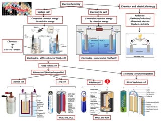
- 1. Types voltaic cell Conversion electrical energy to chemical energy Electrochemistry Electrolytic cellVoltaic cell NH4CI and ZnCI2 Chemical and electrical energy Redox rxn (Oxidation/reduction) Movement electron Produce electricity Conversion chemical energy to electrical energy Electrodes– different metal (Half cell) Electrodes – same metal (Half cell) Chemical rxn Electric current Daniell cell Alkaline cellDry cell Nickel cadmium cell Primary cell (Non rechargeable) MnO2 and KOH Secondary cell (Rechargeable)
- 2. Conversion electrical to chemical energy Electrochemistry ElectrolyticcellVoltaic cell Conversion chemicalto electricalenergy Cathode (+ve) - Reduction Cathode (-ve) - Reduction Vs Electron flow from anode (-ve) to cathode (+ve) electrode Electron flow from anode (+ve) to cathode (-ve) electrode Anode (-ve) Spontaneous rxn Non Spontaneous rxn Anode (-ve) – Oxidation Anode (+ve) – Oxidation ++ О О О О - - Zn → Zn 2+ + 2e (oxidized) Cu2+ + 2e → Cu (reduced) Zn2+ Zn2+ Zn2+ Zn2+- - - - → + + + Cu2+ Cu2+ Cu2+ -e -e + + + - - - X-→ X + -e (oxidized) X - X - X - Anode (+ve) Cathode (-ve) Cathode (+ve) -e -e Y+ + e- → Y (reduced) Y+ Y+ Y+ -e -e -e -e Anode Cathode Voltaic Cell Electrolytic Cell Anode Oxidation Negative (-ve) Oxidation Positive (+ve) Cathode Reduction Positive (+ve) Reduction Negative (-ve) Cation (+ve ion) to cathode (-ve)Anion (-ve ion) to anode (+ve)
- 3. Current– measured in Amperes or Coulombs per second 1A = 1 Coulomb charge pass througha point in 1 second = 1C/s 1 Coulomb charge (electron)= 6.28 x 10 18 electronspassing in 1 second 1 electron/protoncarry charge of – 1.6 x 10 -19 C ( very small) 6.28 x 10 18 electron carry charge of - 1 C Electric current Flow electric charges (electron, -ve) From High electric potential – low potential Due to Potential Difference– measure with ammeter ond electron ond Coulomb A sec.1 .1028.6 sec1 1 1 18 Click here current/voltage Current Electric Current – movingcharges in solid wire or solution Flow of charges - - - Solid/WireSolution/Electrolyte Electron move in random No current flow cause No potential difference Electrons & Protons - - + + 1A = 6.28 x 10¹⁸ e 1 second Video on current/voltage Potential Difference across wire Electron move in one direction Current flow +ve ions -ve ions (cations) (anions) Potential Difference applied/Battery used ItQ t = Time/ s Find amt charges pass through a sol if Current is 2.ooA, time is 15 mins ItQ Current flow Q = Amt Charges/ C I = Current/ A CQ 1800601500.2
- 4. Electric Potential C J Volt 1 1 Potential Diff/Voltage -Measured in Volt with Voltmeter - 1 V = 1 Joule energy released when 1 Coulomb charge pass through 1 point - 1 V = 1 J/C 6V battery - 6J energy for every Coulomb moved bet its terminals. V = Potential Diff I = Current R = Resistance Potential diff bet 2 points is 1 V ↓ 1 J energy released when 1 C charge passes through Voltmeter across 1Volt 1 V Potential Diff/Voltage/PotentialEnergy + - 1 Ω 2 Ω Charges (-ve) flow down A R V I RIV 2 3 6 VV RIV 212 - + - + VV RIV 422 Total current Potential Diff(PD)vs Current PD = Water Pressure PD = 1.5V – 1.5J energy released 1C charge flow down PD – cause charge flow- charge flow = Called CURRENT Potential Diff(PD)vs Current 1.5V = 1.5J/C A DElectric potential/PD/Voltage = Electric Pressure = Volt Electric Current/Current = Charge flow = Amp Electric Potential Energy = Work done to bring a charge to a point = Joule Voltage NOT same as energy, Voltage = energy/charge Battery lift charges, Q to higher potential Potential Energy bet 2 terminals in battery stored as chemical energy 2A 2A
- 5. EMF vs PD V = Potential Diff I = Current R = Resistance Max potential diff bet two electrodes of battery source. + - 1 Ω 2 Ω A R V I RIV 2 3 6 VV RIV 212 VV RIV 422 Total current Current flow Circuit complete Circuit complete ↓ Current flow ↓ Internal resistance (battery - 1Ω) ↓ Terminal PD = 8V (Voltage drop) Potential Diff/Voltage in Volt Symbol for EMF = E or ℰ Click here voltage drop internal resistance No Current flow in circuit EMF (ElectromotiveForce) in Volt Battery = EMF = 9V 9 Volt ).(9 currentnoVEMFV IRV EMF Internal resistance Ir Place voltmeter across – EMF= 9V No current flow. A rR E I rRIE IrIREMFE 1 9 9 )18( 9 )( )( )( VV RIV 881 VV RIV 111 EMF = 8V+1V 8 Volt 1 Volt Voltage measured across terminal = 8V Click here EMF notes Click here PD, PE and I EMF (6V) = 2V + 4V 4 Volt2 Volt Charges passing through wire Current flow Circuit complete
- 6. Series vs Parallel Circuit 3 Ω A R V I RIV 5.0 18 9 VV V RIV 5.2 55.0 VV V RIV 5 105.0 Total Resistance 3 + 10 + 5 = 18Ω Parallel CircuitSeries Circuit EMF (9V) = 2.5V + 5V + 1.5V R = 0.625Ω Voltage same across all component. VT = V1 = V2 = V3 Total current = sum of current in each branch. IT = I1 + I2 + I3 Total equi resistance < value of any individual resistor Total Current Current same in circuit Total voltage = sum of component in series 5 Ω 10 Ω0.5 A VV V RIV 5.1 35.0 Voltage across all component Same = 9V Total Current = sum of all current in each branch Total Resistance 10Ω 2Ω 1Ω AI R V I 9.0 10 9 AI R V I 5.4 2 9 AI R V I 9 1 9 Total current (14.4A) = 0.9A + 4.5A + 9A Ohm’s Law Sum voltage drop equal to voltage source (EMF). VT = V1 + V2 + V3 Current same in all components in series. Total resistance = sum of individual resistances. RT = R1 + R2 + R3 Click here voltage drop Series Circuit Parallel Circuit • Voltage do not flow • Charges/Current flow • Voltage cause current to flow • Voltage ≠ Energy • Battery do not supply electron • Wire contain electron, they flow Electron in wire repel by -ve terminal move in circuit Electron move slowly, drift velocity, electric field move at speed of light Electric signal travel speed of light, bulb light up instantaneously, Electric signal/field travel faster than movement of electron Movement e – cause electric field – travel speed of light – bulb light up Voltage Diff – Pressure diff across Voltage Diff – Cause water/current to flow 14.4A 4.5A0.9A 9A
- 7. Potential Diff bet Zn/Zn2+ Electrode potential Zn/Zn2+ = -ve - Electrode Potential Redox Equilibrium Zn2+ Zn → Zn 2+ + 2e (Oxidation) Zn 2+ + 2e → Zn (Reduction) Zn 2+ + 2e ↔ Zn (At equilibrium) Metal Zn placed in its sol Zn2+ ion Equilibrium bet Zn/Zn2+ Zn metal reactive lose e form Zn2+ Equilibrium shift to right ← Potential Diff form bet Zn/Zn2+ Potential Diff Electrode potential = -ve Zn2+ Zn2+ Zn Zn2+ Zn Zn2+ Zn2+ Zn2+ Zn 2+ + 2e ↔ Zn Equi shift to ← - -- Zn - - - - + + + + + + + + + Voltage of Zn/Zn2+ can’t be measured. Abs electrodepotentialcan’t measured. Only Diff in electrode potentialcan be measured. Cannot measure Abs Potential Metal Cu placed in its sol Cu2+ ion Equilibrium bet Cu/Cu2+ Cu2+ ion gain -2e form Cu Equilibrium shift to left ← Potential Diff form bet Cu/Cu2+ Potential Diff Electrode potential = +ve Cu Cu2+ Cu2+ Cu2+ Cu2+ Cu → Cu2+ + 2e (Oxidation) Cu2+ + 2e → Cu (Reduction) Cu2+ + 2e ↔ Cu (At equilibrium) Cu -e -e -e Cu2+ Cu2+ Cu2+ Cu2+ + 2e ↔ Cu Equi shift to → Zn Half Cell + + + Cu + + + --- - --- ---- -- Potential Diff bet Cu/Cu2+ Electrode potential Cu/Cu2+ = +ve Cannot measure Abs Potential Voltage of Cu/Cu2+can’t be measured. Abs electrodepotentialcan’t measured. Only Diff in electrode potentialcan be measured. Click here chem database (std electrode potential) Click here chem database (std electrode potential) Click here interactive ECS Click here pdf version ECS Cu Half Cell
- 8. PotentialDiff Cu/Cu2+ Electrode potential Cu/Cu2+ = +ve PotentialDiff Zn/Zn2+ Electrode potential Zn/Zn2+ = -ve Zn2+ Zn → Zn 2+ + 2e (Oxidation) Zn 2+ + 2e → Zn (Reduction) Zn 2+ + 2e ↔ Zn (At equilibrium) Zn2+ Zn2+ Zn Zn2+ Zn Zn2+ Zn2+ Zn2+ Zn 2+ + 2e ↔ Zn Equi shift to ← - - - Zn - -- - + ++ + + + + + + Can’t measure Abs Potential Cu Cu2+ Cu2+ Cu2+ Cu2+ Cu → Cu2+ + 2e (Oxidation) Cu2+ + 2e → Cu (Reduction) Cu2+ + 2e ↔ Cu (At equilibrium) Cu -e -e -e Cu2+ Cu2+ Cu2+ Cu2+ + 2e ↔ Cu Equi shift to → Zn Half Cell + + + Cu + + + - Cu Half Cell Zn/Cu Voltaic Cell External circuit – flow of electrons Complete circuit - -- -- - - ---- -- - Connect 2 Half Cell with wire/ salt bridge Zn half cell (-ve) Oxidation Cu half cell (+ve) Reduction Salt Bridge – flow of ions Complete the circuit Cu2+ + 2e → CuZn → Zn 2+ + 2e Zn + Cu2+ → Zn2+ + Cu Anode Cathode Maintain electrical neutrality Salt bridge – saturated KNO3 Zn2+ increase ↑ NO3 - flow in to balance excess Zn2+ Cu2+ decrease ↓, excess –ve ion ↑ K+ flow in to balance loss of Cu2+ Zn Cu -- - - Zn2+ Zn2+ Zn2+ Excess of Zn2+ ion + + ++ - - - - --- - - - - - Excess of –ve ion + + + + ++ + Without Salt Bridge -+ + + + With Salt Bridge (electron unable to flow due to ESF) NO3 - NO3 - NO3 - NO3 - + + + K + K + K + - - - K+ flow in to balance excess of – ion NO3 - flow in to balance excess of + ion 2 Half Cell to make a Voltaic Cell -e -e - - - - + + + +
- 9. PotentialDiff Cu/Cu2+ Electrode potential Cu/Cu2+ = +ve PotentialDiff Zn/Zn2+ Electrode potential Zn/Zn2+ = -ve Zn2+ Zn → Zn 2+ + 2e (Oxidation) Zn 2+ + 2e → Zn (Reduction) Zn 2+ + 2e ↔ Zn (At equilibrium) Zn2+ Zn2+ Zn Zn2+ Zn Zn2+ Zn2+ Zn2+ Zn 2+ + 2e ↔ Zn Equi shift to ← - - - Zn - -- - + ++ + + + + + + Can’t measure Abs Potential Cu Cu2+ Cu2+ Cu2+ Cu2+ Cu → Cu2+ + 2e (Oxidation) Cu2+ + 2e → Cu (Reduction) Cu2+ + 2e ↔ Cu (At equilibrium) Cu -e -e -e Cu2+ Cu2+ Cu2+ Cu2+ + 2e ↔ Cu Equi shift to → + + + Cu + + + - External circuit – flow of electrons Complete circuit - -- -- - - ---- -- - Connect 2 Half Cell with wire/ salt bridge Zn half cell (-ve) Oxidation Cu half cell (+ve) Reduction Voltmeter – High resistance (No current flow) Salt Bridge – flow of ions Complete the circuit Cu2+ + 2e → CuZn → Zn 2+ + 2e 1.10Volt Potential diff can be measured. Voltmeter across – EMF 1.10 Volt Zn + Cu2+ → Zn2+ + Cu Anode Cathode Zn(s) | Zn2+ (aq) || Cu2+ (aq)| Cu (s) Cell diagram Anode Cathode Half Cell Half Cell (Oxidation) (Reduction) Phase boundarySalt Bridge Flow electrons Maintain electrical neutrality Salt bridge – saturated KNO3 Zn2+ increase ↑ NO3 - flow in to balance excess Zn2+ Cu2+ decrease ↓ K+ flow in to balance loss of Cu2+ Zn/Cu Voltaic Cell 2 Half Cell to make a Voltaic Cell Zn Half Cell Cu Half Cell -e -e - - - - + + + +
- 10. PotentialDiff Ag/Ag2+ Electrode potential Ag/Ag2+ = +ve PotentialDiff Zn/Zn2+ Electrode potential Zn/Zn2+ = -ve Zn2+ Zn → Zn 2+ + 2e (Oxidation) Zn 2+ + 2e → Zn (Reduction) Zn 2+ + 2e ↔ Zn (At equilibrium) Zn2+ Zn2+ Zn Zn2+ Zn Zn2+ Zn2+ Zn2+ Zn 2+ + 2e ↔ Zn Equi shift to ← - - - Zn - -- - + ++ + + + + + + Can’t measure Abs Potential Ag Ag+ Ag+ Ag+ Ag+ Ag → Ag+ + e (Oxidation) Ag+ + e → Ag (Reduction) Ag+ + e ↔ Ag (At equilibrium) Ag -e -e -e Ag+ Ag+ Ag+ Ag+ + e ↔ Ag Equi shift to → + + + Ag + + + - External circuit – flow of electrons Complete circuit - -- -- - - ---- -- - Connect 2 Half Cell with wire/ salt bridge Zn half cell (-ve) Oxidation Ag half cell (+ve) Reduction Voltmeter – High resistance (No current flow) Salt Bridge – flow of ions Complete the circuit Ag+ + e → AgZn → Zn 2+ + 2e 1.56Volt Potential diff can be measured. Voltmeter across – EMF 1.56 Volt Zn + 2Ag+ → Zn2+ + 2Ag Anode Cathode Zn(s) | Zn2+ (aq) || Ag+ (aq)| Ag (s) Cell diagram Anode Cathode Half Cell Half Cell (Oxidation) (Reduction) Phase boundarySalt Bridge Flow electrons Maintain electrical neutrality Salt bridge – saturated KNO3 Zn2+ increase ↑ NO3 - flow in to balance excess Zn2+ Ag+ decrease ↓ K+ flow in to balance loss of Ag+ Zn/Ag Voltaic Cell 2 Half Cell to make a Voltaic Cell Zn Half Cell Ag Half Cell Ag Ag+ -e -e - - - - + + + +
- 11. PotentialDiff Ag/Ag2+ Electrode potential Ag/Ag2+ = +ve PotentialDiff Cu/Cu2+ Electrode potential Cu/Cu2+ = -ve Cu2+ Cu → Cu 2+ + 2e (Oxidation) Cu 2+ + 2e → Cu (Reduction) Cu 2+ + 2e ↔ Cu (At equilibrium) Cu2+ Cu2+ Cu Cu2+ Cu Cu2+ Cu2+ Cu2+ Cu 2+ + 2e ↔ Cu Equi shift to ← - - - Cu - -- - + ++ + + + + + + Can’t measure Abs Potential Ag Ag+ Ag+ Ag+ Ag+ Ag → Ag+ + e (Oxidation) Ag+ + e → Ag (Reduction) Ag+ + e ↔ Ag (At equilibrium) Ag -e -e -e Ag+ Ag+ Ag+ Ag+ + e ↔ Ag Equi shift to → + + + Ag + + + - External circuit – flow of electrons Complete circuit - -- -- - - ---- -- - Connect 2 Half Cell with wire/ salt bridge Cu half cell (-ve) Oxidation Ag half cell (+ve) Reduction Voltmeter – High resistance (No current flow) Salt Bridge – flow of ions Complete the circuit Ag+ + e → AgCu → Cu 2+ + 2e 0.46Volt Potential diff can be measured. Voltmeter across – EMF 0.46 Volt Cu + 2Ag+ → Cu2+ + 2Ag Anode Cathode Cu(s) | Cu2+ (aq) || Ag+ (aq)| Ag (s) Cell diagram Anode Cathode Half Cell Half Cell (Oxidation) (Reduction) Phase boundarySalt Bridge Flow electrons Maintain electrical neutrality Salt bridge – saturated KNO3 Cu2+ increase ↑ NO3 - flow in to balance excess Cu2+ Ag+ decrease ↓ K+ flow in to balance loss of Ag+ Cu/Ag Voltaic Cell 2 Half Cell to make a Voltaic Cell Cu Half Cell Ag Half Cell Ag Ag+ Cu Cu2+ -e -e - - - - + + + +
- 12. Standard Electrode Potential Standard HydrogenElectrode (SHE) Platinum coat with Platinum oxide/black – increase surface area for adsorption H2 - catalyze equilibrium bet H2 /H+ - H2 ↔ 2H+ + 2e- Eθ Standard Reference electrode All Cell Potential are measured against • Conc ( 1M) • Pressure (1 atm) • Temp (298K) • Platinum-inert electrode (sys without metal) Standard condition H2 at 1 atm Platinum H2 gas Pt wire Platinum 2H+ + 2e ↔ H2 Eθ = 0V Types of Half Cells Metal/ Ion (M/M+) Gas/ Ion (M/M-) Ion/ Ion (Fe3+/Fe2+) • Pure Zn metal • Conc (1M Zn2+) • Pressure (1 atm) • Temp(298K) Condition Std Zn/Zn2+ Condition Std CI2/CI- • CI2 gas • Platinum electrode • Conc (1M CI-) • Pressure (1 atm) • Temp(298K) • Platinum electrode • Conc (1M Fe3+/Fe2+) • Pressure (1 atm) • Temp(298K) Condition Std Fe3+/ Fe2+ Zn2+ Zn Fe3+/Fe2+ CI- Condition for Standard C A N T M E A S U R E A B S P O T E N T I A L 1 2 3 How to measure electrode potential ? Pt 1M H+ Measure Difference?
- 13. Standard Electrode Potential Std HydrogenElectrode (SHE) Eθ = 0V Types of Half Cells Metal/ Ion (M/M+) Gas/ Ion (M/M+) Ion/ Ion (Fe3+/Fe2+) • Pure Zn metal • Conc (1M Zn2+) • Pressure (1 atm) • Temp(298K) Condition Std Zn/Zn2+ Condition Std CI2/CI- • CI2 gas • Platinum electrode • Conc (1M CI-) • Pressure (1 atm) • Temp(298K) • Platinum electrode • Conc (1M Fe3+/Fe2+) • Pressure (1 atm) • Temp(298K) Condition Std Fe3+/ Fe2+ Zn2+ Zn Fe3+/Fe2+ 1 2 3 Connect to SHE Connect to SHE Connect to SHE Eθ = 0V Eθ = 0V Eθ = -0.76V Standard electrode potential Zn/Zn2+ = -0.76V Eθ cell = -0.76V Eθ = +0.77V Eθ = +1.35V Standard electrode potential Fe3+/Fe2+ = +0.77V Eθ cell = +0.77V Standard electrode potential CI2 /CI- = +1.35V Eθ cell = +1.35V Eθ = -0.76V Eθ = +0.77V Eθ = +1.35V 2 Half Cellwith SHE as referenceelectrode CI- Pt + + + Pt
- 14. Standard Electrode Potential Std Electrode Potential diff systems Eθ = 0V Eθ = 0V Eθ = 0V Eθ = -0.76V Standard electrode potential Zn/Zn2+ = -0.76V Eθ cell = -0.76V Eθ = +0.77V Eθ = +1.35V Standard electrode potential Fe3+/Fe2+ = +0.77V Eθ cell = +0.77V Standard electrode potential CI2 /CI- = +1.35V Eθ cell = +1.35V Eθ = -0.76V Eθ = +0.77V Eθ = +1.35V STANDARD Reduction potential – Hydrogen as std Oxidized sp ↔ Reduced sp Eθ/V Li+ + e- ↔ Li -3.04 K+ + e- ↔ K -2.93 Ca2+ + 2e- ↔ Ca -2.87 Na+ + e- ↔ Na -2.71 Mg 2+ + 2e- ↔ Mg -2.37 Al3+ + 3e- ↔ AI -1.66 Mn2+ + 2e- ↔ Mn -1.19 H2O + e- ↔ 1/2H2 + OH- -0.83 Zn2+ + 2e- ↔ Zn -0.76 Fe2+ + 2e- ↔ Fe -0.45 Ni2+ + 2e- ↔ Ni -0.26 Sn2+ + 2e- ↔ Sn -0.14 Pb2+ + 2e- ↔ Pb -0.13 H+ + e- ↔ 1/2H2 0.00 Cu2+ + e- ↔ Cu+ +0.15 SO4 2- + 4H+ + 2e- ↔ H2SO3 + H2O +0.17 Cu2+ + 2e- ↔ Cu +0.34 1/2O2 + H2O +2e- ↔ 2OH- +0.40 Cu+ + e- ↔ Cu +0.52 1/2I2 + e- ↔ I- +0.54 Fe3+ + e- ↔ Fe2+ +0.77 Ag+ + e- ↔ Ag +0.80 1/2Br2 + e- ↔ Br- +1.07 1/2O2 + 2H+ +2e- ↔ H2O +1.23 Cr2O7 2-+14H+ +6e- ↔ 2Cr3+ + 7H2O +1.33 1/2CI2 + e- ↔ CI- +1.35 MnO4 - + 8H+ + 5e- ↔ Mn2+ + 4H2O +1.51 1/2F2 + e- ↔ F +2.87 -ve reduction potential +ve reduction potential Click here std analogy video Click here std analogy Click here chem database (std electrode potential) Compared to H2 as std Eθ cell/CellPotential= EMF in volt EMF prod when half cell connect to SHE at std condition Std electrode potential written as std reduction potential
- 15. Zn half cell (-ve) Oxidation H2 half cell (+ve) Reduction Anode Cathode Zn(s) | Zn2+ (aq) || H+ (aq) , H2(g) | Pt (s) Cell diagram Anode Cathode Half Cell Half Cell (Oxidation) (Reduction) Salt Bridge Flow electrons Eθ cell = Eθ (cathode) – Eθ (anode) Eθ cell = 0.00 – ( Eθ Zn ) 0.76 = 0.00 - Eθ Zn Eθ Zn = -0.76V Zn2+ + 2e ↔ Zn Eθ = ? 2H+ + 2e ↔ H2 Eθ = 0.00V Std electrode potential as std reductionpotential Find Eθ cell (use formula) Eθ cell = Eθ (cathode) – Eθ (anode) Oxidized sp ↔ Reduced sp Eθ/V Li+ + e- ↔ Li -3.04 K+ + e- ↔ K -2.93 Ca2+ + 2e- ↔ Ca -2.87 Na+ + e- ↔ Na -2.71 Mg 2+ + 2e- ↔ Mg -2.37 Al3+ + 3e- ↔ AI -1.66 Mn2+ + 2e- ↔ Mn -1.19 H2O + e- ↔ 1/2H2 + OH- -0.83 Zn2+ + 2e- ↔ Zn ???? Fe2+ + 2e- ↔ Fe -0.45 Ni2+ + 2e- ↔ Ni -0.26 Sn2+ + 2e- ↔ Sn -0.14 Pb2+ + 2e- ↔ Pb -0.13 H+ + e- ↔ 1/2H2 0.00 Cu2+ + e- ↔ Cu+ +0.15 SO4 2- + 4H+ + 2e- ↔ H2SO3 + H2O +0.17 Cu2+ + 2e- ↔ Cu +0.34 1/2O2 + H2O +2e- ↔ 2OH- +0.40 Cu+ + e- ↔ Cu +0.52 1/2I2 + e- ↔ I- +0.54 Fe3+ + e- ↔ Fe2+ + 0.77 Ag+ + e- ↔ Ag +0.80 1/2Br2 + e- ↔ Br- +1.07 1/2O2 + 2H+ +2e- ↔ H2O +1.23 Cr2O7 2-+14H+ +6e- ↔ 2Cr3+ + 7H2O +1.33 1/2CI2 + e- ↔ CI- +1.35 MnO4 - + 8H+ + 5e- ↔ Mn2+ + 4H2O +1.51 1/2F2 + e- ↔ F +2.87 -0.76V +ve/high electrode potentialis cathode(+) -ve/ low electrode potential is anode (-) Electronsflow from anode (- ) to cathode (+ ) Eθ Zn/H2 = 0.76V Zn/H2 Eθ value DO NOT depend on stoichiometric coefficient (Independentof stoichiometric eqn) Zn Zn2+ H+ Pt H2 - - - + -e Zn/H2 Cell Determine Eθ cell Zn/Zn2+ Zn2+ + 2e →Zn Eθ = -0.76V
- 16. H2 half cell (-ve) Oxidation Fe3+/2+ half cell (+ve) Reduction Anode Cathode Pt(s) | H2, H+ (aq) || Fe3+ Fe2+ | Pt (s) Cell diagram Anode Cathode Half Cell Half Cell (Oxidation) (Reduction) Salt Bridge Flow electrons Std electrode potential as std reductionpotential Find Eθ cell (use formula) Eθ cell = Eθ (cathode) – Eθ (anode) Oxidized sp ↔ Reduced sp Eθ/V Li+ + e- ↔ Li -3.04 K+ + e- ↔ K -2.93 Ca2+ + 2e- ↔ Ca -2.87 Na+ + e- ↔ Na -2.71 Mg 2+ + 2e- ↔ Mg -2.37 Al3+ + 3e- ↔ AI -1.66 Mn2+ + 2e- ↔ Mn -1.19 H2O + e- ↔ 1/2H2 + OH- -0.83 Zn2+ + 2e- ↔ Zn -0.76 Fe2+ + 2e- ↔ Fe -0.45 Ni2+ + 2e- ↔ Ni -0.26 Sn2+ + 2e- ↔ Sn -0.14 Pb2+ + 2e- ↔ Pb -0.13 H+ + e- ↔ 1/2H2 0.00 Cu2+ + e- ↔ Cu+ +0.15 SO4 2- + 4H+ + 2e- ↔ H2SO3 + H2O +0.17 Cu2+ + 2e- ↔ Cu +0.34 1/2O2 + H2O +2e- ↔ 2OH- +0.40 Cu+ + e- ↔ Cu +0.52 1/2I2 + e- ↔ I- +0.54 Fe3+ + e- ↔ Fe2+ ????? Ag+ + e- ↔ Ag +0.80 1/2Br2 + e- ↔ Br- +1.07 1/2O2 + 2H+ +2e- ↔ H2O +1.23 Cr2O7 2-+14H+ +6e- ↔ 2Cr3+ + 7H2O +1.33 1/2CI2 + e- ↔ CI- +1.35 MnO4 - + 8H+ + 5e- ↔ Mn2+ + 4H2O +1.51 1/2F2 + e- ↔ F +2.87 +0.77V +ve/high electrode potentialis cathode(+) -ve/ low electrode potential is anode (-) Electronsflow from anode (- ) to cathode (+ ) Pt Fe3+ H+ Pt H2 + + +-- -e H2 /Fe3+,Fe2+ Cell H2 /Fe3+,Fe2+ 2H+ + 2e ↔ H2 Eθ = 0.00V Fe3+ + e ↔ Fe2+ Eθ = ???? Eθ cell = Eθ (cathode) – Eθ (anode) Eθ cell = Eθ Fe3+ – (-0.00) 0.77 = Eθ Fe3+ Determine Eθ cell Fe 3+/Fe2+ Eθ H2 /Fe3+ = 0.77V Fe3+ + e →Fe2+ Eθ = +0.77V Eθ value DO NOT depend on stoichiometric coefficient (Independentof stoichiometric eqn)
- 17. H2 half cell (-ve) Oxidation CI2 half cell (+ve) Reduction Anode Pt(s) | H2, H+ (aq) || CI2 ,CI- | Pt (s) Cell diagram Anode Cathode Half Cell Half Cell (Oxidation) (Reduction) Salt Bridge Flow electrons Std electrode potential as std reductionpotential Find Eθ cell (use formula) Eθ cell = Eθ (cathode) – Eθ (anode) Oxidized sp ↔ Reduced sp Eθ/V Li+ + e- ↔ Li -3.04 K+ + e- ↔ K -2.93 Ca2+ + 2e- ↔ Ca -2.87 Na+ + e- ↔ Na -2.71 Mg 2+ + 2e- ↔ Mg -2.37 Al3+ + 3e- ↔ AI -1.66 Mn2+ + 2e- ↔ Mn -1.19 H2O + e- ↔ 1/2H2 + OH- -0.83 Zn2+ + 2e- ↔ Zn -0.76 Fe2+ + 2e- ↔ Fe -0.45 Ni2+ + 2e- ↔ Ni -0.26 Sn2+ + 2e- ↔ Sn -0.14 Pb2+ + 2e- ↔ Pb -0.13 H+ + e- ↔ 1/2H2 0.00 Cu2+ + e- ↔ Cu+ +0.15 SO4 2- + 4H+ + 2e- ↔ H2SO3 + H2O +0.17 Cu2+ + 2e- ↔ Cu +0.34 1/2O2 + H2O +2e- ↔ 2OH- +0.40 Cu+ + e- ↔ Cu +0.52 1/2I2 + e- ↔ I- +0.54 Fe3+ + e- ↔ Fe2+ + 0.77 Ag+ + e- ↔ Ag +0.80 1/2Br2 + e- ↔ Br- +1.07 1/2O2 + 2H+ +2e- ↔ H2O +1.23 Cr2O7 2-+14H+ +6e- ↔ 2Cr3+ + 7H2O +1.33 1/2CI2 + e- ↔ CI- ????? MnO4 - + 8H+ + 5e- ↔ Mn2+ + 4H2O +1.51 1/2F2 + e- ↔ F +2.87 +1.35V +ve/high electrode potentialis cathode(+) -ve/ low electrode potential is anode (-) Electronsflow from anode (- ) to cathode (+ ) H+ Pt H2 -- -e H2 /CI2 Cell 2H+ + 2e ↔ H2 Eθ = 0.00V CI + e ↔ CI- Eθ = ????? Eθ cell = Eθ (cathode) – Eθ (anode) Eθ cell = Eθ CI2 – (-0.00) 1.35 = Eθ CI2 H2 /CI2 Cell + Pt CI - CI2 Determine Eθ cell H2 /CI2 Eθ H2 /CI2 = 1.35V 1/2CI- + e →CI- Eθ = +1.35V Eθ value DO NOT depend on stoichiometric coefficient (Independentof stoichiometric eqn)
- 18. Zn half cell (-ve) Oxidation Cu half cell (+ve) Reduction Anode Cathode Zn(s) | Zn2+ (aq) || Cu2+ (aq) | Cu (s) Cell diagram Anode Cathode Half Cell Half Cell (Oxidation) (Reduction) Salt Bridge Flow electrons Zn/Cu Voltaic Cell -e -e Zn/Cu half cell Eθ cell = Eθ (cathode) – Eθ (anode) Eθ cell = +0.34 – (-0.76) = +1.10V Zn 2+ + 2e ↔ Zn (anode) Eθ = -0.76V Cu2+ + 2e ↔ Cu (cathode) Eθ = +0.34V Std electrode potential as std reduction potential Find Eθ cell (use reduction potential)Find Eθ cell (use formula) Zn + Cu2+ → Zn2+ + Cu Eθ = ????? Eθ cell = Eθ (cathode) – Eθ (anode) Zn 2+ + 2e ↔ Zn Eθ = -0.76V Cu2+ + 2e ↔ Cu Eθ = +0.34V Zn ↔ Zn2+ + 2e Eθ = +0.76V Cu2+ + 2e ↔ Cu Eθ = +0.34V Zn + Cu2+ → Zn 2+ + Cu Eθ = +1.10V Oxidized sp ↔ Reduced sp Eθ/V Li+ + e- ↔ Li -3.04 K+ + e- ↔ K -2.93 Ca2+ + 2e- ↔ Ca -2.87 Na+ + e- ↔ Na -2.71 Mg 2+ + 2e- ↔ Mg -2.37 Al3+ + 3e- ↔ AI -1.66 Mn2+ + 2e- ↔ Mn -1.19 H2O + e- ↔ 1/2H2 + OH- -0.83 Zn2+ + 2e- ↔ Zn - 0.76 Fe2+ + 2e- ↔ Fe -0.45 Ni2+ + 2e- ↔ Ni -0.26 Sn2+ + 2e- ↔ Sn -0.14 Pb2+ + 2e- ↔ Pb -0.13 H+ + e- ↔ 1/2H2 0.00 Cu2+ + e- ↔ Cu+ +0.15 SO4 2- + 4H+ + 2e- ↔ H2SO3 + H2O +0.17 Cu2+ + 2e- ↔ Cu + 0.34 1/2O2 + H2O +2e- ↔ 2OH- +0.40 Cu+ + e- ↔ Cu +0.52 1/2I2 + e- ↔ I- +0.54 Fe3+ + e- ↔ Fe2+ +0.77 Ag+ + e- ↔ Ag +0.80 1/2Br2 + e- ↔ Br- +1.07 1/2O2 + 2H+ +2e- ↔ H2O +1.23 Cr2O7 2-+14H+ +6e- ↔ 2Cr3+ + 7H2O +1.33 1/2CI2 + e- ↔ CI- +1.35 MnO4 - + 8H+ + 5e- ↔ Mn2+ + 4H2O +1.51 1/2F2 + e- ↔ F +2.87 + +1.10 V Eθ Zn/Cu = 1.10V Cu2+ +ve/high electrode potentialis cathode(+) -ve/ low electrode potential is anode (-) Electronsflow from anode (- ) to cathode (+ ) - - - - Zn Cu + + + + Eθ value DO NOT depend on stoichiometric coefficient (Independentof stoichiometric eqn)
- 19. Zn half cell (-ve) Oxidation Ag half cell (+ve) Reduction Anode Cathode Zn(s) | Zn2+ (aq) || Ag+ (aq) | Ag (s) Cell diagram Anode Cathode Half Cell Half Cell (Oxidation) (Reduction) Salt Bridge Flow electrons Zn/Ag Voltaic Cell -e -e Zn/Ag half cell Eθ cell = Eθ (cathode) – Eθ (anode) Eθ cell = +0.80 – (-0.76) = +1.56V Zn 2+ + 2e ↔ Zn (anode) Eθ = -0.76V Ag+ + e ↔ Ag(cathode) Eθ = +0.80V Std electrode potential as std reduction potential Find Eθ cell (use reduction potential)Find Eθ cell (use formula) Zn + Ag+ → Zn2+ + Ag Eθ = ????? Eθ cell = Eθ (cathode) – Eθ (anode) Zn 2+ + 2e ↔ Zn Eθ = -0.76V Ag+ + e ↔ Ag Eθ = +0.80V Zn ↔ Zn2+ + 2e Eθ = +0.76V Ag+ + e ↔ Ag Eθ = +0.80V Zn + Ag+ → Zn 2+ + Ag Eθ = +1.56V Oxidized sp ↔ Reduced sp Eθ/V Li+ + e- ↔ Li -3.04 K+ + e- ↔ K -2.93 Ca2+ + 2e- ↔ Ca -2.87 Na+ + e- ↔ Na -2.71 Mg 2+ + 2e- ↔ Mg -2.37 Al3+ + 3e- ↔ AI -1.66 Mn2+ + 2e- ↔ Mn -1.19 H2O + e- ↔ 1/2H2 + OH- -0.83 Zn2+ + 2e- ↔ Zn - 0.76 Fe2+ + 2e- ↔ Fe -0.45 Ni2+ + 2e- ↔ Ni -0.26 Sn2+ + 2e- ↔ Sn -0.14 Pb2+ + 2e- ↔ Pb -0.13 H+ + e- ↔ 1/2H2 0.00 Cu2+ + e- ↔ Cu+ +0.15 SO4 2- + 4H+ + 2e- ↔ H2SO3 + H2O +0.17 Cu2+ + 2e- ↔ Cu +0.34 1/2O2 + H2O +2e- ↔ 2OH- +0.40 Cu+ + e- ↔ Cu +0.52 1/2I2 + e- ↔ I- +0.54 Fe3+ + e- ↔ Fe2+ +0.77 Ag+ + e- ↔ Ag + 0.80 1/2Br2 + e- ↔ Br- +1.07 1/2O2 + 2H+ +2e- ↔ H2O +1.23 Cr2O7 2-+14H+ +6e- ↔ 2Cr3+ + 7H2O +1.33 1/2CI2 + e- ↔ CI- +1.36 MnO4 - + 8H+ + 5e- ↔ Mn2+ + 4H2O +1.51 1/2F2 + e- ↔ F +2.87 + +1.56 V Ag Eθ Zn/Ag = 1.56V Ag+ +ve/high electrode potentialis cathode(+) -ve/ low electrode potential is anode (-) Electronsflow from anode (- ) to cathode (+ ) - - - - + + + + Zn Eθ value DO NOT dependon stoichiometric coefficient (Independentof stoichiometric eqn)
- 20. Cu half cell (-ve) Oxidation Ag half cell (+ve) Reduction Anode Cathode Cu(s) | Cu2+ (aq) || Ag+ (aq) | Ag (s) Cell diagram Anode Cathode Half Cell Half Cell (Oxidation) (Reduction) Salt Bridge Flow electrons Cu/Ag Voltaic Cell -e -e Cu/Ag half cell Eθ cell = Eθ (cathode) – Eθ (anode) Eθ cell = +0.80 – (+0.34) = +0.46V Cu 2+ + 2e ↔ Cu (anode) Eθ = +0.34V Ag+ + e ↔ Ag(cathode) Eθ = +0.80V Std electrode potential as std reductionpotential Find Eθ cell (use reduction potential)Find Eθ cell (use formula) Cu + 2Ag+ → Cu2+ + 2Ag Eθ = ????? Eθ cell = Eθ (cathode) – Eθ (anode) Cu 2+ + 2e ↔ Cu Eθ = +0.34V Ag+ + e ↔ Ag Eθ = +0.80V Cu ↔ Cu2+ + 2e Eθ = -0.34V 2Ag+ + e ↔ 2Ag Eθ = +0.80V Cu + 2Ag+→ Cu 2+ + 2Ag Eθ = +0.46V Oxidized sp ↔ Reduced sp Eθ/V Li+ + e- ↔ Li -3.04 K+ + e- ↔ K -2.93 Ca2+ + 2e- ↔ Ca -2.87 Na+ + e- ↔ Na -2.71 Mg 2+ + 2e- ↔ Mg -2.37 Al3+ + 3e- ↔ AI -1.66 Mn2+ + 2e- ↔ Mn -1.19 H2O + e- ↔ 1/2H2 + OH- -0.83 Zn2+ + 2e- ↔ Zn -0.76 Fe2+ + 2e- ↔ Fe -0.45 Ni2+ + 2e- ↔ Ni -0.26 Sn2+ + 2e- ↔ Sn -0.14 Pb2+ + 2e- ↔ Pb -0.13 H+ + e- ↔ 1/2H2 0.00 Cu2+ + e- ↔ Cu+ +0.15 SO4 2- + 4H+ + 2e- ↔ H2SO3 + H2O +0.17 Cu2+ + 2e- ↔ Cu +0.34 1/2O2 + H2O +2e- ↔ 2OH- +0.40 Cu+ + e- ↔ Cu +0.52 1/2I2 + e- ↔ I- +0.54 Fe3+ + e- ↔ Fe2+ +0.77 Ag+ + e- ↔ Ag +0.80 1/2Br2 + e- ↔ Br- +1.07 1/2O2 + 2H+ +2e- ↔ H2O +1.23 Cr2O7 2-+14H+ +6e- ↔ 2Cr3+ + 7H2O +1.33 1/2CI2 + e- ↔ CI- +1.36 MnO4 - + 8H+ + 5e- ↔ Mn2+ + 4H2O +1.51 1/2F2 + e- ↔ F +2.87 + +0.46V AgCu Cu2+ Half cell- high electrodepotential is cathode(+) Half cell - low electrodepotential is anode (-) Electronsflow from anode (- ) to cathode (+ ) Eθ Cu/Ag = 0.46V Ag+ - - - - + + + + Eθ value DO NOT depend on stoichiometric coefficient (Independentof stoichiometric eqn)
- 21. Mn half cell (-ve) Oxidation Ni half cell (+ve) Reduction Anode Cathode Mn(s) | Mn2+ (aq) || Ni2+ (aq) | Ni (s) Cell diagram Anode Cathode Half Cell Half Cell (Oxidation) (Reduction) Salt Bridge Flow electrons Mn/Ni Voltaic Cell -e -e Mn/Ni half cells Eθ cell = Eθ (cathode) – Eθ (anode) Eθ cell = -0.26 – (-1.19) = +0.93V Mn 2+ + 2e ↔ Mn (anode) Eθ = -1.19V Ni2+ + 2e ↔ Ni (cathode) Eθ = -0.26V Std electrode potential as std reduction potential Find Eθ cell (use reduction potential)Find Eθ cell (use formula) Mn + Ni2+ → Mn2+ + Ni Eθ = ????? Eθ cell = Eθ (cathode) – Eθ (anode) Mn 2+ + 2e ↔ Mn Eθ = -1.19V Ni2+ + 2e ↔ Ni Eθ = -0.26V Mn ↔ Mn2+ + 2e Eθ = +1.19V Ni2+ + 2e ↔ Ni Eθ = -0.26V Mn + Ni2+ → Mn2+ + Ni Eθ = +0.93V Oxidized sp ↔ Reduced sp Eθ/V Li+ + e- ↔ Li -3.04 K+ + e- ↔ K -2.93 Ca2+ + 2e- ↔ Ca -2.87 Na+ + e- ↔ Na -2.71 Mg 2+ + 2e- ↔ Mg -2.37 Al3+ + 3e- ↔ AI -1.66 Mn2+ + 2e- ↔ Mn -1.19 H2O + e- ↔ 1/2H2 + OH- -0.83 Zn2+ + 2e- ↔ Zn -0.76 Fe2+ + 2e- ↔ Fe -0.45 Ni2+ + 2e- ↔ Ni - 0.26 Sn2+ + 2e- ↔ Sn -0.14 Pb2+ + 2e- ↔ Pb -0.13 H+ + e- ↔ 1/2H2 0.00 Cu2+ + e- ↔ Cu+ +0.15 SO4 2- + 4H+ + 2e- ↔ H2SO3 + H2O +0.17 Cu2+ + 2e- ↔ Cu +0.34 1/2O2 + H2O +2e- ↔ 2OH- +0.40 Cu+ + e- ↔ Cu +0.52 1/2I2 + e- ↔ I- +0.54 Fe3+ + e- ↔ Fe2+ +0.77 Ag+ + e- ↔ Ag +0.80 1/2Br2 + e- ↔ Br- +1.07 1/2O2 + 2H+ +2e- ↔ H2O +1.23 Cr2O7 2-+14H+ +6e- ↔ 2Cr3+ + 7H2O +1.33 1/2CI2 + e- ↔ CI- +1.36 MnO4 - + 8H+ + 5e- ↔ Mn2+ + 4H2O +1.51 1/2F2 + e- ↔ F +2.87 + +0.93 V Eθ Mn/Ni = 0.93V Ni2+ +ve/high electrode potentialis cathode(+) -ve/ low electrode potential is anode (-) Electronsflow from anode (- ) to cathode (+ ) - - - - NiMn + + + +Mn2+ Eθ value DO NOT depend on stoichiometric coefficient (Independentof stoichiometric eqn)
- 22. Fe half cell (-ve) Oxidation MnO4- half cell (+ve) Reduction Anode Cathode Fe(s) | Fe2+ (aq) || MnO4 - ,H+, Mn2+ | Pt (s) Cell diagram Anode Cathode Half Cell Half Cell (Oxidation) (Reduction) Salt Bridge Flow electrons Fe/MnO4 - Voltaic Cell -e -e Fe/MnO4 - half cells Eθ cell = Eθ (cathode) – Eθ (anode) Eθ cell = +1.51 – (-0.45) = +1.96V Fe2+ + 2e ↔ Fe Eθ = -0.45V MnO4 - + 5e ↔ Mn2+ + 4H2O E θ = +1.51V Std electrode potential asstd reduction potential Find Eθ cell (use reduction potential)Find Eθ cell (use formula) 5Fe + 2MnO4 - + 16H+→5Fe2+ +2Mn2+ + 8H2O Eθ = ? Eθ cell = Eθ (cathode) – Eθ (anode) Fe 2+ + 2e ↔ Fe Eθ = -0.45V MnO4 - + 5e ↔ Mn2+ + 4H2O Eθ = +1.51V Fe ↔ Fe2+ + 2e Eθ = +0.45V MnO4 - +5e ↔ Mn2+ + 4H2O Eθ = +1.51V Fe + MnO4 - → Mn2+ + Fe2+ Eθ = +1.96V Oxidized sp ↔ Reduced sp Eθ/V Li+ + e- ↔ Li -3.04 K+ + e- ↔ K -2.93 Ca2+ + 2e- ↔ Ca -2.87 Na+ + e- ↔ Na -2.71 Mg 2+ + 2e- ↔ Mg -2.37 Al3+ + 3e- ↔ AI -1.66 Mn2+ + 2e- ↔ Mn -1.19 H2O + e- ↔ 1/2H2 + OH- -0.83 Zn2+ + 2e- ↔ Zn -0.76 Fe2+ + 2e- ↔ Fe -0.45 Ni2+ + 2e- ↔ Ni -0.26 Sn2+ + 2e- ↔ Sn -0.14 Pb2+ + 2e- ↔ Pb -0.13 H+ + e- ↔ 1/2H2 0.00 Cu2+ + e- ↔ Cu+ +0.15 SO4 2- + 4H+ + 2e- ↔ H2SO3 + H2O +0.17 Cu2+ + 2e- ↔ Cu +0.34 1/2O2 + H2O +2e- ↔ 2OH- +0.40 Cu+ + e- ↔ Cu +0.52 1/2I2 + e- ↔ I- +0.54 Fe3+ + e- ↔ Fe2+ +0.77 Ag+ + e- ↔ Ag +0.80 1/2Br2 + e- ↔ Br- +1.07 1/2O2 + 2H+ +2e- ↔ H2O +1.23 Cr2O7 2-+14H+ +6e- ↔ 2Cr3+ + 7H2O +1.33 1/2CI2 + e- ↔ CI- +1.36 MnO4 - + 8H+ + 5e- ↔ Mn2+ + 4H2O +1.51 1/2F2 + e- ↔ F +2.87 + +1.96V PtFe Fe2+ Eθ Fe/MnO4 - = 1.96V MnO4 - Mn2+ Using platinumelectrode +ve/high electrode potentialis cathode(+) -ve/ low electrode potential is anode (-) Electronsflow from anode (- ) to cathode (+ ) - - - - + + + + Eθ value DO NOT depend on stoichiometric coefficient (Independentof stoichiometric eqn)
- 23. Zn half cell (-ve) Oxidation Fe3+/2+ half cell (+ve) Reduction Anode Cathode Zn(s) | Zn2+ (aq) || Fe3+ , Fe2+ (aq) | Pt (s) Cell diagram Anode Cathode Half Cell Half Cell (Oxidation) (Reduction) Salt Bridge Flow electrons Zn/Fe3+,Fe2+ Cell -e -e Eθ cell = Eθ (cathode) – Eθ (anode) Eθ cell = +0.77 – (-0.76) = +1.53V Zn2+ + 2e ↔ Zn Eθ = -0.76V Fe3+ + e ↔ Fe2+ Eθ = +0.77V Std electrode potential asstd reduction potential Find Eθ cell (use reduction potential)Find Eθ cell (use formula) Zn + 2Fe3+→ Zn2+ +2Fe2+ Eθ = ? Eθ cell = Eθ (cathode) – Eθ (anode) Zn 2+ + 2e ↔ Zn Eθ = -0.76V Fe3+ + e ↔ Fe2+ Eθ = +0.77V Zn ↔ Zn2+ + 2e Eθ = +0.76V Fe3+ +e ↔ Fe2+ Eθ = +0.77V Zn + 2Fe3+ → Zn2+ + 2Fe2+ Eθ = +1.53V Oxidized sp ↔ Reduced sp Eθ/V Li+ + e- ↔ Li -3.04 K+ + e- ↔ K -2.93 Ca2+ + 2e- ↔ Ca -2.87 Na+ + e- ↔ Na -2.71 Mg 2+ + 2e- ↔ Mg -2.37 Al3+ + 3e- ↔ AI -1.66 Mn2+ + 2e- ↔ Mn -1.19 H2O + e- ↔ 1/2H2 + OH- -0.83 Zn2+ + 2e- ↔ Zn -0.76 Fe2+ + 2e- ↔ Fe -0.45 Ni2+ + 2e- ↔ Ni -0.26 Sn2+ + 2e- ↔ Sn -0.14 Pb2+ + 2e- ↔ Pb -0.13 H+ + e- ↔ 1/2H2 0.00 Cu2+ + e- ↔ Cu+ +0.15 SO4 2- + 4H+ + 2e- ↔ H2SO3 + H2O +0.17 Cu2+ + 2e- ↔ Cu +0.34 1/2O2 + H2O +2e- ↔ 2OH- +0.40 Cu+ + e- ↔ Cu +0.52 1/2I2 + e- ↔ I- +0.54 Fe3+ + e- ↔ Fe2+ + 0.77 Ag+ + e- ↔ Ag +0.80 1/2Br2 + e- ↔ Br- +1.07 1/2O2 + 2H+ +2e- ↔ H2O +1.23 Cr2O7 2-+14H+ +6e- ↔ 2Cr3+ + 7H2O +1.33 1/2CI2 + e- ↔ CI- +1.36 MnO4 - + 8H+ + 5e- ↔ Mn2+ + 4H2O +1.51 1/2F2 + e- ↔ F +2.87 + +1.53V PtZn Zn2+ +ve/high electrode potentialis cathode(+) -ve/ low electrode potential is anode (-) Electronsflow from anode (- ) to cathode (+ ) Eθ Zn/Fe3+ = 1.53V Fe3+- Fe2+ Using platinumelectrode Zn/Fe3+,Fe2+ - - - - + + + + Eθ value DO NOT depend on stoichiometric coefficient (Independentof stoichiometric eqn)
- 24. Zn half cell (-ve) Oxidation I2 half cell (+ve) Reduction Anode Cathode Zn(s) | Zn2+ (aq) || I2 , I- (aq) | Pt (s) Cell diagram Anode Cathode Half Cell Half Cell (Oxidation) (Reduction) Salt Bridge Flow electrons Zn/I2 , I- Cell -e -e Eθ cell = Eθ (cathode) – Eθ (anode) Eθ cell = +0.54 – (-0.76) = +1.30V Zn2+ + 2e ↔ Zn Eθ = -0.76V I2 + 2e ↔ 2I- Eθ = +0.54V Std electrode potential asstd reduction potential Find Eθ cell (use reduction potential)Find Eθ cell (use formula) Zn + I2 → Zn2+ +2I- Eθ = ? Eθ cell = Eθ (cathode) – Eθ (anode) Zn ↔ Zn2+ + 2e Eθ = +0.76V I2 + 2e ↔ 2I- Eθ = +0.54V Zn + I2 → Zn2+ + 2I- Eθ = +1.30V Oxidized sp ↔ Reduced sp Eθ/V Li+ + e- ↔ Li -3.04 K+ + e- ↔ K -2.93 Ca2+ + 2e- ↔ Ca -2.87 Na+ + e- ↔ Na -2.71 Mg 2+ + 2e- ↔ Mg -2.37 Al3+ + 3e- ↔ AI -1.66 Mn2+ + 2e- ↔ Mn -1.19 H2O + e- ↔ 1/2H2 + OH- -0.83 Zn2+ + 2e- ↔ Zn -0.76 Fe2+ + 2e- ↔ Fe -0.45 Ni2+ + 2e- ↔ Ni -0.26 Sn2+ + 2e- ↔ Sn -0.14 Pb2+ + 2e- ↔ Pb -0.13 H+ + e- ↔ 1/2H2 0.00 Cu2+ + e- ↔ Cu+ +0.15 SO4 2- + 4H+ + 2e- ↔ H2SO3 + H2O +0.17 Cu2+ + 2e- ↔ Cu +0.34 1/2O2 + H2O +2e- ↔ 2OH- +0.40 Cu+ + e- ↔ Cu +0.52 1/2I2 + e- ↔ I- +0.54 Fe3+ + e- ↔ Fe2+ + 0.77 Ag+ + e- ↔ Ag +0.80 1/2Br2 + e- ↔ Br- +1.07 1/2O2 + 2H+ +2e- ↔ H2O +1.23 Cr2O7 2-+14H+ +6e- ↔ 2Cr3+ + 7H2O +1.33 1/2CI2 + e- ↔ CI- +1.36 MnO4 - + 8H+ + 5e- ↔ Mn2+ + 4H2O +1.51 1/2F2 + e- ↔ F +2.87 + +1.30V PtZn Zn2+ +ve/high electrode potentialis cathode(+) -ve/ low electrode potential is anode (-) Electronsflow from anode (- ) to cathode (+ ) Eθ Zn/I2 = 1.30V I-- I2 Using platinumelectrode - - - - + + + + Zn/I2 , I- Zn2+ + 2e ↔ Zn Eθ = -0.76V I2 + 2e ↔ 2I- Eθ = +0.54V Eθ value DO NOT depend on stoichiometric coefficient (Independentof stoichiometric eqn)
- 25. Zn half cell (-ve) Oxidation H2 half cell (+ve) Reduction Anode Cathode Zn(s) | Zn2+ (aq) || H+ (aq) , H2(g) | Pt (s) Cell diagram Anode Cathode Half Cell Half Cell (Oxidation) (Reduction) Salt Bridge Flow electrons Eθ cell = Eθ (cathode) – Eθ (anode) Eθ cell = 0.00 – (-0.76) = +0.76V Zn2+ + 2e ↔ Zn Eθ = -0.76V 2H+ + 2e ↔ H2 Eθ = 0.00V Std electrode potential as std reductionpotential Find Eθ cell (use reduction potential)Find Eθ cell (use formula) Zn + 2H+→ Zn2+ + H2 Eθ = ? Eθ cell = Eθ (cathode) – Eθ (anode) Zn 2+ + 2e ↔ Zn Eθ = -0.76V 2H+ + 2e ↔ H2 Eθ = 0.00V Zn ↔ Zn2+ + 2e Eθ = +0.76V 2H+ +2e ↔ H2 Eθ = 0.00V Zn + 2H+ → Zn2+ + H2 Eθ = +0.76V Oxidized sp ↔ Reduced sp Eθ/V Li+ + e- ↔ Li -3.04 K+ + e- ↔ K -2.93 Ca2+ + 2e- ↔ Ca -2.87 Na+ + e- ↔ Na -2.71 Mg 2+ + 2e- ↔ Mg -2.37 Al3+ + 3e- ↔ AI -1.66 Mn2+ + 2e- ↔ Mn -1.19 H2O + e- ↔ 1/2H2 + OH- -0.83 Zn2+ + 2e- ↔ Zn -0.76 Fe2+ + 2e- ↔ Fe -0.45 Ni2+ + 2e- ↔ Ni -0.26 Sn2+ + 2e- ↔ Sn -0.14 Pb2+ + 2e- ↔ Pb -0.13 H+ + e- ↔ 1/2H2 0.00 Cu2+ + e- ↔ Cu+ +0.15 SO4 2- + 4H+ + 2e- ↔ H2SO3 + H2O +0.17 Cu2+ + 2e- ↔ Cu +0.34 1/2O2 + H2O +2e- ↔ 2OH- +0.40 Cu+ + e- ↔ Cu +0.52 1/2I2 + e- ↔ I- +0.54 Fe3+ + e- ↔ Fe2+ + 0.77 Ag+ + e- ↔ Ag +0.80 1/2Br2 + e- ↔ Br- +1.07 1/2O2 + 2H+ +2e- ↔ H2O +1.23 Cr2O7 2-+14H+ +6e- ↔ 2Cr3+ + 7H2O +1.33 1/2CI2 + e- ↔ CI- +1.36 MnO4 - + 8H+ + 5e- ↔ Mn2+ + 4H2O +1.51 1/2F2 + e- ↔ F +2.87 + +0.76V +ve/high electrode potentialis cathode(+) -ve/ low electrode potential is anode (-) Electronsflow from anode (- ) to cathode (+ ) Eθ Zn/H2 = 0.76V Using platinumelectrode/H2 Zn/H2 Zn Zn2+ H+ Pt H2 - - - + -e Zn/H2 Cell Eθ value DO NOT depend on stoichiometric coefficient (Independentof stoichiometric eqn)
- 26. H2 half cell (-ve) Oxidation Ag half cell (+ve) Reduction Anode Cathode Pt(s) | H2, H+ (aq) || Ag+ (aq) | Ag (s) Cell diagram Anode Cathode Half Cell Half Cell (Oxidation) (Reduction) Salt Bridge Flow electrons H2/Ag Cell Eθ cell = Eθ (cathode) – Eθ (anode) Eθ cell = +0.80 – (-0.00) = +0.80V 2H+ + 2e ↔ H2 Eθ = 0.00V Ag+ + e ↔ Ag Eθ = +0.80V Std electrode potential as std reductionpotential Find Eθ cell (use reduction potential)Find Eθ cell (use formula) H2 + 2Ag+ → 2H+ + 2Ag Eθ = ? Eθ cell = Eθ (cathode) – Eθ (anode) H2 ↔ 2H+ + 2e Eθ = +0.00V 2Ag+ +2e ↔ 2Ag Eθ = +0.80V H2 + 2Ag+ → 2H+ + 2Ag Eθ = +0.80V Oxidized sp ↔ Reduced sp Eθ/V Li+ + e- ↔ Li -3.04 K+ + e- ↔ K -2.93 Ca2+ + 2e- ↔ Ca -2.87 Na+ + e- ↔ Na -2.71 Mg 2+ + 2e- ↔ Mg -2.37 Al3+ + 3e- ↔ AI -1.66 Mn2+ + 2e- ↔ Mn -1.19 H2O + e- ↔ 1/2H2 + OH- -0.83 Zn2+ + 2e- ↔ Zn -0.76 Fe2+ + 2e- ↔ Fe -0.45 Ni2+ + 2e- ↔ Ni -0.26 Sn2+ + 2e- ↔ Sn -0.14 Pb2+ + 2e- ↔ Pb -0.13 H+ + e- ↔ 1/2H2 0.00 Cu2+ + e- ↔ Cu+ +0.15 SO4 2- + 4H+ + 2e- ↔ H2SO3 + H2O +0.17 Cu2+ + 2e- ↔ Cu +0.34 1/2O2 + H2O +2e- ↔ 2OH- +0.40 Cu+ + e- ↔ Cu +0.52 1/2I2 + e- ↔ I- +0.54 Fe3+ + e- ↔ Fe2+ + 0.77 Ag+ + e- ↔ Ag +0.80 1/2Br2 + e- ↔ Br- +1.07 1/2O2 + 2H+ +2e- ↔ H2O +1.23 Cr2O7 2-+14H+ +6e- ↔ 2Cr3+ + 7H2O +1.33 1/2CI2 + e- ↔ CI- +1.36 MnO4 - + 8H+ + 5e- ↔ Mn2+ + 4H2O +1.51 1/2F2 + e- ↔ F +2.87 + +0.80V +ve/high electrode potentialis cathode(+) -ve/ low electrode potential is anode (-) Electronsflow from anode (- ) to cathode (+ ) Eθ H2 /Ag = 0.80V Using platinumelectrode/H2 H2/Ag Ag Ag+ H+ Pt H2 2H+ + 2e ↔ H2 Eθ = 0.00V Ag+ + e ↔ Ag Eθ = +0.80V + + +-- -e Eθ value DO NOT depend on stoichiometric coefficient (Independentof stoichiometric eqn)
- 27. H2 half cell (-ve) Oxidation Fe3+/2+ half cell (+ve) Reduction Anode Cathode Pt(s) | H2, H+ (aq) || Fe3+ Fe2+ | Pt (s) Cell diagram Anode Cathode Half Cell Half Cell (Oxidation) (Reduction) Salt Bridge Flow electrons Std electrode potential as std reductionpotential Find Eθ cell (use reduction potential)Find Eθ cell (use formula) H2 + 2Fe3+ → 2H+ + 2Fe Eθ = ? Eθ cell = Eθ (cathode) – Eθ (anode) H2 ↔ 2H+ + 2e Eθ = +0.00V 2Fe3+ +2e ↔ 2Fe2+ Eθ = +0.77V H2 + 2Ag+ → 2H+ + 2Ag Eθ = +0.77V Oxidized sp ↔ Reduced sp Eθ/V Li+ + e- ↔ Li -3.04 K+ + e- ↔ K -2.93 Ca2+ + 2e- ↔ Ca -2.87 Na+ + e- ↔ Na -2.71 Mg 2+ + 2e- ↔ Mg -2.37 Al3+ + 3e- ↔ AI -1.66 Mn2+ + 2e- ↔ Mn -1.19 H2O + e- ↔ 1/2H2 + OH- -0.83 Zn2+ + 2e- ↔ Zn -0.76 Fe2+ + 2e- ↔ Fe -0.45 Ni2+ + 2e- ↔ Ni -0.26 Sn2+ + 2e- ↔ Sn -0.14 Pb2+ + 2e- ↔ Pb -0.13 H+ + e- ↔ 1/2H2 0.00 Cu2+ + e- ↔ Cu+ +0.15 SO4 2- + 4H+ + 2e- ↔ H2SO3 + H2O +0.17 Cu2+ + 2e- ↔ Cu +0.34 1/2O2 + H2O +2e- ↔ 2OH- +0.40 Cu+ + e- ↔ Cu +0.52 1/2I2 + e- ↔ I- +0.54 Fe3+ + e- ↔ Fe2+ + 0.77 Ag+ + e- ↔ Ag +0.80 1/2Br2 + e- ↔ Br- +1.07 1/2O2 + 2H+ +2e- ↔ H2O +1.23 Cr2O7 2-+14H+ +6e- ↔ 2Cr3+ + 7H2O +1.33 1/2CI2 + e- ↔ CI- +1.36 MnO4 - + 8H+ + 5e- ↔ Mn2+ + 4H2O +1.51 1/2F2 + e- ↔ F +2.87 + +0.77V +ve/high electrode potentialis cathode(+) -ve/ low electrode potential is anode (-) Electronsflow from anode (- ) to cathode (+ ) Eθ H2 /Fe3+ = 0.77V Using platinum electrode/H2 Pt Fe3+ H+ Pt H2 + + +-- -e H2 /Fe3+,Fe2+ Cell H2 /Fe3+,Fe2+ 2H+ + 2e ↔ H2 Eθ = 0.00V Fe3+ + e ↔ Fe2+ Eθ = +0.77V 2H+ + 2e ↔ H2 Eθ = 0.00V Fe3+ + e ↔ Fe2+ Eθ = +0.77V Eθ cell = Eθ (cathode) – Eθ (anode) Eθ cell = +0.77– (-0.00) = +0.77V Eθ value DO NOT depend on stoichiometric coefficient (Independentof stoichiometric eqn)
- 28. H2 half cell (-ve) Oxidation CI2 half cell (+ve) Reduction Anode Cathode Pt(s) | H2, H+ (aq) || CI2 ,CI- | Pt (s) Cell diagram Anode Cathode Half Cell Half Cell (Oxidation) (Reduction) Salt Bridge Flow electrons Std electrode potential as std reductionpotential Find Eθ cell (use reduction potential)Find Eθ cell (use formula) CI2 + H2 → 2CI- + 2H+ Eθ = ? Eθ cell = Eθ (cathode) – Eθ (anode) H2 ↔ 2H+ + 2e Eθ = +0.00V CI2 +2e ↔ 2CI- Eθ = +1.35V H2 + CI2 → 2H+ + 2CI- Eθ = +1.35V Oxidized sp ↔ Reduced sp Eθ/V Li+ + e- ↔ Li -3.04 K+ + e- ↔ K -2.93 Ca2+ + 2e- ↔ Ca -2.87 Na+ + e- ↔ Na -2.71 Mg 2+ + 2e- ↔ Mg -2.37 Al3+ + 3e- ↔ AI -1.66 Mn2+ + 2e- ↔ Mn -1.19 H2O + e- ↔ 1/2H2 + OH- -0.83 Zn2+ + 2e- ↔ Zn -0.76 Fe2+ + 2e- ↔ Fe -0.45 Ni2+ + 2e- ↔ Ni -0.26 Sn2+ + 2e- ↔ Sn -0.14 Pb2+ + 2e- ↔ Pb -0.13 H+ + e- ↔ 1/2H2 0.00 Cu2+ + e- ↔ Cu+ +0.15 SO4 2- + 4H+ + 2e- ↔ H2SO3 + H2O +0.17 Cu2+ + 2e- ↔ Cu +0.34 1/2O2 + H2O +2e- ↔ 2OH- +0.40 Cu+ + e- ↔ Cu +0.52 1/2I2 + e- ↔ I- +0.54 Fe3+ + e- ↔ Fe2+ + 0.77 Ag+ + e- ↔ Ag +0.80 1/2Br2 + e- ↔ Br- +1.07 1/2O2 + 2H+ +2e- ↔ H2O +1.23 Cr2O7 2-+14H+ +6e- ↔ 2Cr3+ + 7H2O +1.33 1/2CI2 + e- ↔ CI- +1.35 MnO4 - + 8H+ + 5e- ↔ Mn2+ + 4H2O +1.51 1/2F2 + e- ↔ F +2.87 + +1.35V +ve/high electrode potentialis cathode(+) -ve/ low electrode potential is anode (-) Electronsflow from anode (- ) to cathode (+ ) Eθ H2 /CI2 = 1.35V Using platinum electrode/H2 H+ Pt H2 -- -e H2 /CI2 Cell 2H+ + 2e ↔ H2 Eθ = 0.00V CI + e ↔ CI- Eθ = +1.35V Eθ cell = Eθ (cathode) – Eθ (anode) Eθ cell = +1.35 – (-0.00) = +1.35V H2 /CI2 Cell 2H+ + 2e ↔ H2 Eθ = 0.00V CI + e ↔ CI- Eθ = +1.35V + Pt CI - CI2 Eθ value DO NOT depend on stoichiometric coefficient (Independentof stoichiometric eqn)
- 29. Standard Electrode Potential STANDARD Reduction potential – H2 as std Oxidized sp ↔ Reduced sp Eθ/V Li+ + e- ↔ Li -3.04 K+ + e- ↔ K -2.93 Ca2+ + 2e- ↔ Ca -2.87 Na+ + e- ↔ Na -2.71 Mg 2+ + 2e- ↔ Mg -2.37 Al3+ + 3e- ↔ AI -1.66 Mn2+ + 2e- ↔ Mn -1.19 H2O + e- ↔ H2+OH- -0.83 Zn2+ + 2e- ↔ Zn -0.76 Fe2+ + 2e- ↔ Fe -0.45 Ni2+ + 2e- ↔ Ni -0.26 Sn2+ + 2e- ↔ Sn -0.14 Pb2+ + 2e- ↔ Pb -0.13 H+ + e- ↔ 1/2H2 0.00 Cu2+ + e- ↔ Cu+ +0.15 SO4 2- + 4H+ + 2e- ↔ H2SO3 + H2O +0.17 Cu2+ + 2e- ↔ Cu +0.34 1/2O2 + H2O +2e- ↔ 2OH- +0.40 Cu+ + e- ↔ Cu +0.52 1/2I2 + e- ↔ I- +0.54 Fe3+ + e- ↔ Fe2+ +0.77 Ag+ + e- ↔ Ag +0.80 1/2Br2 + e- ↔ Br- +1.07 1/2O2 + 2H+ +2e- ↔ H2O +1.23 Cr2O7 2-+14H+ +6e- ↔ 2Cr3+ +7H2O +1.33 1/2CI2 + e- ↔ CI- +1.36 MnO4 - + 8H+ + 5e- ↔ Mn2+ + 4H2O +1.51 1/2F2 + e- ↔ F +2.87 -ve reduction potential +ve reduction potential Compared to H2 as std Eθ cell/CellPotential= EMF in volt EMF when half cell connect to SHE std condition Std potentialwritten as std reduction potential TOP right • High ↑ tendency lose e • Li → Li + + e • Eθ Li = +3.04V • STRONG reducingAgent •Oxi favourable (Eθ =+ve) STRONG Reducing Agent WEAK Reducing Agent BOTTOM right • Low ↓ tendency lose e • F - → 1/2F2 + e • Eθ F2 = - 2.87V • WEAK reducingAgent •Oxi NOT favourable (Eθ =-ve) WEAK Oxidizing Agent Strong Oxidizing Agent TOP left • Low ↓ tendency gain e • Li+ + e → Li • Eθ Li= - 3.04V • WEAK oxidizingAgent • Red NOT favourable (Eθ =-ve) BOTTOM left • High ↑ tendency gain e • F2 + 2e → 2F- • Eθ F2= +2.87V • STRONG oxidizing Agent •Red favourable (Eθ =+ve)
- 30. Acknowledgements Thanks to source of pictures and video used in this presentation Thanks to Creative Commons for excellent contribution on licenses http://creativecommons.org/licenses/ http://spmchemistry.onlinetuition.com.my/2013/10/electrolytic-cell.html http://www.chemguide.co.uk/physical/redoxeqia/introduction.html http://educationia.tk/reduction-potential-table http://2012books.lardbucket.org/books/principles-of-general-chemistry-v1.0/s23- electrochemistry.html Prepared by Lawrence Kok Check out more video tutorials from my site and hope you enjoy this tutorial http://lawrencekok.blogspot.com