SlideShare a Scribd company logo
IOSR Journal of Electrical and Electronics Engineering (IOSR-JEEE)
e-ISSN: 2278-1676,p-ISSN: 2320-3331, Volume 6, Issue 2 (May. - Jun. 2013), PP 65-69
www.iosrjournals.org
www.iosrjournals.org 65 | Page
Application of SVM Technique for Three Phase Three Leg Ac/Ac
Converter Topology
T.C. Srinivasa Rao1
, T.C. Subramanyam2
, N. Srinivas3
, G. Sandeep4
1 3 4
(Department of EEE, Vardhaman College of Engg, India)
2
(Department of EEE, School of Engg, NNRESGI, India)
Abstract: Ac–ac power conversion, the most popular topologies are indirect ac–ac converters with a dc link
matrix converters and direct pulse width modulation (PWM) ac–ac converters. The indirect ac–ac converters
and matrix converters can provide variable output voltage and variable frequency. However, for applications,
where only voltage regulation is needed, the direct PWM ac–ac converters are used to perform as ac choppers
or power line conditioners with the following features: the provision of a better power factor and efficiency, low
harmonic current in line, single-stage conversion, simple topology, ease of control, smaller size, and lower cost.
The ac–ac conversions or ac–ac line conditioners can also perform conditioning, isolating, and altering of the
incoming power in addition to voltage regulation. The direct PWM ac–ac converters can be derived from the
dc–dc topologies, where all the unidirectional switches are substituted by bidirectional devices.
This paper presents simulation of a Three-phase Three-leg Ac/Ac Converter simulation design using
reduced number of power semiconductor devices, here nine IGBTs are used. This converter features sinusoidal
inputs and outputs, unity power factor, and more importantly, low manufacturing cost. The experimental results
from a 5kVA prototype system are provided.
Index Terms -AC/AC converter, reduced switch count topology, SVPWM
I. Introduction
THREE-PHASE ac/dc/ac and ac/ac converters with variable frequency (VF) and variable voltage operation
have found broad applications in the industry. The most popular configuration uses voltage source inverter
(VSI) with a diode rectifier as the front end for adjustable speed drives (ASDs), uninterruptible power supplies
(UPS), and other industrial applications. This configuration features low cost and reliable operation due to the
use of a diode rectifier, but it generates highly distorted input line currents and does not have regenerative or
dynamic braking capability. These problems can be mitigated by using a back-to- back two-level voltage source
converter, shown inFig.1, where a PWM voltage source rectifier is used to replace the diode rectifier the back-
to-back converter configuration requires 12 active switches such as IGBTs with increased manufacture cost. In
addition, it needs a large size dc capacitor. To reduce the device count and minimize/eliminate the dc capacitor
filter, various converter topologies have been proposed in the literature.
Fig.1Conventional back-to-back converter topology
One of the promising converter topologies is the matrix converter. This converter presents a radical
change in topology and directly converts a fixed ac input voltage to an adjustable ac output voltage. It is capable
of bi-directional energy transfer for the supply to the load or vice versa. There is no dc link circuit, and therefore
the dc capacitor filter in the back-to-back converter is not required. However, the matrix converter normally
requires 18 IGBT switches and its switching scheme is complex. The high cost and complex control have made
this topology less attractive.
The proposed three-phase nine-switch converter topology has only three legs with three switches
installed on each of them. The novelty here is that the middle switch in each individual leg is shared by both the
rectifier and the inverter, thereby reducing the switch count by 33% and 50% in comparison to the B2B 2L-
VSC. The input power is delivered to the output partially through the middle three switches and partially
through a quasi-dc-link circuit. The circuit can be considered that the rectifier of the nine-switch converter is
composed of the top three and middle three switches, whereas the inverter consists of the middle three and
bottom three switches.The converter uses space vector PWM (SVM) method which is an advanced
Application Of Svm Technique For Three Phase Three Leg Ac/Ac Converter Topology
www.iosrjournals.org 66 | Page
computation-intensive PWM method and is possibly the best among all the PWM techniques for variable-
frequency drive applications.
II. Space Vector Modulation
The space vector PWM (SVM) method is an advanced computation-intensive PWM method and is
possibly the best among all the PWM techniques for variable-frequency drive applications. Because of its
superior performance characteristics, it has been finding wide speed applications in recent years. The desired
three phase voltages at the output of the inverter could be represented by an equivalent vector V rotating in the
counter clock wise direction as shown in Fig.3. The magnitude of this vector is related to the magnitude of the
output voltage (Fig.4) and the time this vector takes to complete one revolution is the same as the fundamental
time period of the output voltage.
Fig.2Output voltage vector in the α-βplane
Fig.3 Output line voltages in time domain
Let us consider the situation when the desired line-to-line output voltage vector V is in sector 1 as
shown in Fig.3. This vector could be synthesized by the pulse-width modulation (PWM) of the two adjacent
SSV’s V1 (pnn) and V2 (ppn), the duty cycle of each being d1 and d2, respectively, and the zero vector V7(nnn)
/ V8(ppp) ) of duty cycle d0:
d1V1 + d2V2 =V=m Vg ejθ
………………………..(1)
d1 + d2 + d0=0 ………..…………….(2)
Where, 0 ≤m ≤0.866, is the modulation index. This would correspond to a maximum line-to-line voltage of
1.0Vg, which is 15% more than conventional sinusoidal PWM as shown.
Fig.4 Synthesis of the required output voltage vector in sector 1
Application Of Svm Technique For Three Phase Three Leg Ac/Ac Converter Topology
www.iosrjournals.org 67 | Page
All SVM schemes and most of the other PWM algorithms use Eqns. (1) and (2) for the output voltage
synthesis. The modulation algorithms that use non-adjacent SSV's have been shown to produce higher THD
and/or switching losses and are not analyzed here, although some of them, e.g. hysteresis, can be very simple to
implement and can provide faster transient response. The duty cycles d1, d2, and d0, are uniquely determined,
and Eqns. (1) and (2) , the only difference between PWM schemes that use adjacent vectors is the choice of the
zero vector(s) and the sequence in which the vectors are applied within the switching cycle.
The degrees of freedom we have in the choice of a given modulation algorithm is:
1) The choice of the zero vector; whether we would like to use V7(ppp) or V8(nnn) or both,
2) Sequencing of the vectors
3) Splitting of the duty cycles of the vectors without introducing additional commutations.
2.1 Output voltages of three-phase inverter
S1 through S6 are the six power transistors that shape the output voltages When an upper switch is
turned on (i.e., a, b or c is “1”), the corresponding lower switch is turned off (i.e., a', b' or c' is “0”).
Eight possible combinations of on and off patterns for the three upper transistors (S1, S3, S5)
Line to line voltage vector [Vab Vbc Vca]t
---
(3)
Line to neutral (phase) voltage vector [Van Vbn Vcn]t
--------------(4)
Table1. Tabulation of Output voltages of three-phase inverter
2.2 Basic switching vectors and Sectors
 6 active vectors (V1,V2, V3, V4, V5, V6)
1. Axes of a hexagonal.
2. DC link voltage is supplied to the load.
3. Each sector (1 to 6): 60 degrees.
 Two zero vectors (V0, V7)
1. At origin
2. No voltage is supplied to the load
Application Of Svm Technique For Three Phase Three Leg Ac/Ac Converter Topology
www.iosrjournals.org 68 | Page
III. Nine-Switch Converter Topology
Fig.5 shows the proposed three-phase nine- switch converter topology. This converter has three legs
with three switches per leg. The novelty of this converter is that the middle switch in each of the three converter
legs is shared by the rectifier and inverter, thereby reducing the switch count by 33% and 50% in comparison to
the back-to-back converter and matrix converter, respectively. The input power is delivered to the output
partially through the middle three switches and partially through a quasi dc link circuit. For the convenience of
discussion, we can consider that the rectifier of the nine-switch converter is composed of top three and middle
three switches.
Fig.5 proposed three-phase nine- switch converter topology
IV. Simulation Analysis
The performance of the proposed nine-switch converter topology is simulated by simulink software.
The utility supply is rated 208V and 60Hz with a supply inductance of L= 2.5mH. The converter is loaded with
a three phase RL load of Rs=8 ohms and L= 2.5mH. The dc capacitor Cdl is 2350 µF. The rectifier is controlled
by a vector control scheme with unity power factor operation. The inverter output voltage is not detected and
therefore is not tightly controlled. The switching frequency of both rectifier and inverter is 3240Hz.Both CF and
VF modes of operation are investigated.
Fig.6Three phase Input voltage
Fig7. Three phase input Current
Fig8. Rectifier Line current(Ix)
Fig9. Pulses to IGBTS
Fig10. Inverter Output current(Ix)
Application Of Svm Technique For Three Phase Three Leg Ac/Ac Converter Topology
www.iosrjournals.org 69 | Page
Fig11.Inverter output voltage(vxy)
V. Conclusion
A novel nine-switch PWM ac/ac converter topology using SVM technique was proposed in this paper.
The topology uses only nine IGBT devices for ac to ac conversion through a quasi dc-link circuit. Compared
with the conventional back-to-back PWM VSC using 12 switches and the matrix converter that uses 18, the
number of switches in the proposed converter is reduced by 33% and 50%, respectively. The proposed converter
features sinusoidal inputs and outputs, unity input power factor, and low manufacturing cost. The operating
principle of the converter was elaborated, and modulation schemes for constant and VF operations were
developed. Simulation results including a semiconductor loss analysis was provided, which reveal that the
proposed converter, while working in CF mode, has an overall higher efficiency than the B2B 2L-VSC at the
expense of uneven loss distribution. However, the VF-mode version requires IGBT devices with higher ratings
and dissipates significantly higher losses, and thus, is not as attractive as its counterpart. Experimental
verification is carried out on a 5-kVA prototype system.
This paper analyzed the Back to Back inverter topology, and the more complex three-phase-leg
topologies with the modulation concepts and derived carrier-based reference equations verified in simulation for
all presented voltage-type -source inverters, and experimentally for a three-phase-leg -source inverter.
The paper presents the Three-phase Three-leg Ac/Ac converter topology using Space vector Modulation
technique for IGBT pulses. Experiments have been carried out to verify the validity of the proposed scheme.
Reference
[1] B . Wu, High-power Converters and AC Drives. Piscatawa y, NJ:IEEE/Wiley, 2006.
[2] B . Singh, B. N. Singh, A. Chandra, K. Al-Haddad, A. Pandey, and D. P. Ko thari, “A review of three-phase improved p ower
quality AC – DC converters,” IEEE Trans. I nd. Electron., vol. 51, no. 3, pp. 641–660, Jun. 2004.
[3] F. B laabjerg, S. Frey sson, H. H. Hansen, and S. Hansen, “A new op-timized space-vector m odulation strategy for a component-
minimized vo ltage source inverter,” IEEE Trans. Power Electron., vol. 12, no. 4, pp. 704–714, Jul. 1997.
[4] R . L. A. R ibeiro, C. B. Jacobina, E. R . C . d a Silva, and A. M. N. Lima, “AC/AC converter with four switch three phase
structures,” in Proc. I EEE PESC , 1996, vol. 1, pp. 134–139.
[5] K. Gi-Taek and T. A. Lipo, “VSI-PWM rectifier/inverter system with a reduced switch count,” IEEE Trans. Ind. Appl., vol. 32, no. 6,
pp. 1331– 1337, Nov./Dec. 1996.
[6] A. B ouscayrol, B. Francois, P. Delarue, and J. Niiranen, “Control imple- mentation o f a five-leg AC–AC converter to supply a
three-phase induction machine,” IEEE Trans. Power Electron., vol. 20, no. 1, pp. 107–115, Jan. 2005.
[7] C. B. Jacobina, I. S. de Freitas, E. R. C. da Silva, A. M. N. Lima, and R. L. A. Ribeiro, “Reduced switch count DC-link AC–AC five-
leg converter,”IEEE Trans. Power Electron., vol. 21, no. 5, pp. 1301–1310, Sep. 2006.
[8] C. B. Jacobina, I. S. de Freitas, and A. M. N. Lima, “DC-link three-phaseto- three-phase four-leg converters,” IEEE Trans. Ind.
Electron., vol. 54, no. 4, pp. 1953–1961, Aug. 2007.
[9] J. Minibock and J. W. Kolar, “Novel concept for mains voltage proportional input current shaping of a VIENNA rectifier eliminating
controller multipliers,” IEEE Trans. Ind. Electron., vol. 52, no. 1, pp. 162–170, Feb. 2005.
[10] T. Nussbaumer, M. Baumann, and J.W. Kolar, “Comprehensive design of a three-phase three-switch buck-type PWM rectifier,”
IEEE Trans. Power Electron., vol. 22, no. 2, pp. 551–562, Mar. 2007.
[11] F. A. B. Batista and I. Barbi, “Space vector modulation applied to threephase three-switch two-level unidirectional PWMrectifier,”
IEEE Trans. Power Electron., vol. 22, no. 6, pp. 2245–2252, Nov. 2007.
[12] P. W. Wheeler, J. Rodriguez, J. C. Clare, L. Empringham, and A. Weinstein, “Matrix converters: A technology review,” IEEE
Trans.Ind. Electron., vol. 49, no. 2, pp. 276–288, Apr. 2002.
[13] L.Wei, T. A. Lipo, andH.Chan, “Matrix converter topologies with reduced number of switches,” in Proc. IEEE PESC, 2002, vol. 1,
pp. 57–63.
[14] J.W. Kolar, F. Schafmeister, S. D. Round, and H. Ertl, “Novel three-phase AC–AC sparse matrix converters,” IEEE Trans. Power
Electron., vol. 22, no. 5, pp. 1649–1661, Sep. 2007.

More Related Content

What's hot

Power factor improvement in switched reluctance motor drive using pwm
Power factor improvement in switched reluctance motor drive using pwmPower factor improvement in switched reluctance motor drive using pwm
Power factor improvement in switched reluctance motor drive using pwm
IAEME Publication
 

What's hot (20)

Fuzzy Logic Controller Based High Frequency Link AC-AC Converter For Voltage ...
Fuzzy Logic Controller Based High Frequency Link AC-AC Converter For Voltage ...Fuzzy Logic Controller Based High Frequency Link AC-AC Converter For Voltage ...
Fuzzy Logic Controller Based High Frequency Link AC-AC Converter For Voltage ...
 
Torque Ripple Minimization of a BLDC Motor Drive by Using Electronic Commutat...
Torque Ripple Minimization of a BLDC Motor Drive by Using Electronic Commutat...Torque Ripple Minimization of a BLDC Motor Drive by Using Electronic Commutat...
Torque Ripple Minimization of a BLDC Motor Drive by Using Electronic Commutat...
 
Comparative Study of Five-Level and Seven-Level Inverter Controlled by Space ...
Comparative Study of Five-Level and Seven-Level Inverter Controlled by Space ...Comparative Study of Five-Level and Seven-Level Inverter Controlled by Space ...
Comparative Study of Five-Level and Seven-Level Inverter Controlled by Space ...
 
Asymmetrical Cascaded Multi Level Inverter using Control Freedom Pulse width ...
Asymmetrical Cascaded Multi Level Inverter using Control Freedom Pulse width ...Asymmetrical Cascaded Multi Level Inverter using Control Freedom Pulse width ...
Asymmetrical Cascaded Multi Level Inverter using Control Freedom Pulse width ...
 
Implementation on the dSPACE 1104 of VOC-SVM based anti-windup PI Controller ...
Implementation on the dSPACE 1104 of VOC-SVM based anti-windup PI Controller ...Implementation on the dSPACE 1104 of VOC-SVM based anti-windup PI Controller ...
Implementation on the dSPACE 1104 of VOC-SVM based anti-windup PI Controller ...
 
HARMONIC ANALYSIS OF THREE LEVEL DIODE CLAMPED INVERTER
HARMONIC ANALYSIS OF THREE LEVEL DIODE CLAMPED INVERTERHARMONIC ANALYSIS OF THREE LEVEL DIODE CLAMPED INVERTER
HARMONIC ANALYSIS OF THREE LEVEL DIODE CLAMPED INVERTER
 
PWM control techniques for three phase three level inverter drives
PWM control techniques for three phase three level inverter drivesPWM control techniques for three phase three level inverter drives
PWM control techniques for three phase three level inverter drives
 
Power factor improvement in switched reluctance motor drive using pwm
Power factor improvement in switched reluctance motor drive using pwmPower factor improvement in switched reluctance motor drive using pwm
Power factor improvement in switched reluctance motor drive using pwm
 
11 12 sep17 18aug 8416 9975-1-ed (edit)
11 12 sep17 18aug 8416 9975-1-ed (edit)11 12 sep17 18aug 8416 9975-1-ed (edit)
11 12 sep17 18aug 8416 9975-1-ed (edit)
 
Simulation Of A 4-Switch,3-Phase Inverter Fed Induction Motor (IM) Drive System
Simulation Of A 4-Switch,3-Phase Inverter Fed Induction Motor (IM) Drive SystemSimulation Of A 4-Switch,3-Phase Inverter Fed Induction Motor (IM) Drive System
Simulation Of A 4-Switch,3-Phase Inverter Fed Induction Motor (IM) Drive System
 
Harmonic Minimization In Multilevel Inverters By Using PSO
Harmonic Minimization In Multilevel Inverters By Using PSOHarmonic Minimization In Multilevel Inverters By Using PSO
Harmonic Minimization In Multilevel Inverters By Using PSO
 
Design and Development of Digital control based Asymmetric Multilevel Inverte...
Design and Development of Digital control based Asymmetric Multilevel Inverte...Design and Development of Digital control based Asymmetric Multilevel Inverte...
Design and Development of Digital control based Asymmetric Multilevel Inverte...
 
H6 Transformer less Topology and Its Modulation Strategy for Mitigating Cm Cu...
H6 Transformer less Topology and Its Modulation Strategy for Mitigating Cm Cu...H6 Transformer less Topology and Its Modulation Strategy for Mitigating Cm Cu...
H6 Transformer less Topology and Its Modulation Strategy for Mitigating Cm Cu...
 
Modeling and Simulation of a Carrier-based PWM Voltage Source Inverter for a ...
Modeling and Simulation of a Carrier-based PWM Voltage Source Inverter for a ...Modeling and Simulation of a Carrier-based PWM Voltage Source Inverter for a ...
Modeling and Simulation of a Carrier-based PWM Voltage Source Inverter for a ...
 
Multilevel Inverters for PV Applications
Multilevel Inverters for PV ApplicationsMultilevel Inverters for PV Applications
Multilevel Inverters for PV Applications
 
Three Phase Digitally Controlled Power Factor Improvement System
Three Phase Digitally Controlled Power Factor Improvement SystemThree Phase Digitally Controlled Power Factor Improvement System
Three Phase Digitally Controlled Power Factor Improvement System
 
Analysis Approach for Five Phase Two-Level Voltage Source Inverter with PWM T...
Analysis Approach for Five Phase Two-Level Voltage Source Inverter with PWM T...Analysis Approach for Five Phase Two-Level Voltage Source Inverter with PWM T...
Analysis Approach for Five Phase Two-Level Voltage Source Inverter with PWM T...
 
K1102016673
K1102016673K1102016673
K1102016673
 
Commutation torque ripple in bldc by sepic and npc
Commutation torque ripple in bldc by sepic and npcCommutation torque ripple in bldc by sepic and npc
Commutation torque ripple in bldc by sepic and npc
 
Lz3620532059
Lz3620532059Lz3620532059
Lz3620532059
 

Viewers also liked

[IJET V2I5P12] Authors: Mr. Harikrishnan U, Dr. Bos Mathew Jos, Mr.Thomas P R...
[IJET V2I5P12] Authors: Mr. Harikrishnan U, Dr. Bos Mathew Jos, Mr.Thomas P R...[IJET V2I5P12] Authors: Mr. Harikrishnan U, Dr. Bos Mathew Jos, Mr.Thomas P R...
[IJET V2I5P12] Authors: Mr. Harikrishnan U, Dr. Bos Mathew Jos, Mr.Thomas P R...
IJET - International Journal of Engineering and Techniques
 
Power electronic drives ppt
Power electronic drives pptPower electronic drives ppt
Power electronic drives ppt
Sai Manoj
 

Viewers also liked (8)

[IJET V2I5P12] Authors: Mr. Harikrishnan U, Dr. Bos Mathew Jos, Mr.Thomas P R...
[IJET V2I5P12] Authors: Mr. Harikrishnan U, Dr. Bos Mathew Jos, Mr.Thomas P R...[IJET V2I5P12] Authors: Mr. Harikrishnan U, Dr. Bos Mathew Jos, Mr.Thomas P R...
[IJET V2I5P12] Authors: Mr. Harikrishnan U, Dr. Bos Mathew Jos, Mr.Thomas P R...
 
Defense Dunisha Presentation
Defense Dunisha PresentationDefense Dunisha Presentation
Defense Dunisha Presentation
 
Electrical and Electronics Engineering : Power electronics, THE GATE ACADEMY
Electrical and Electronics Engineering : Power electronics, THE GATE ACADEMYElectrical and Electronics Engineering : Power electronics, THE GATE ACADEMY
Electrical and Electronics Engineering : Power electronics, THE GATE ACADEMY
 
Sinusoidal PWM and Space Vector Modulation For Two Level Voltage Source Conve...
Sinusoidal PWM and Space Vector Modulation For Two Level Voltage Source Conve...Sinusoidal PWM and Space Vector Modulation For Two Level Voltage Source Conve...
Sinusoidal PWM and Space Vector Modulation For Two Level Voltage Source Conve...
 
Single Phase to Three Phase Converter
Single Phase to Three Phase Converter Single Phase to Three Phase Converter
Single Phase to Three Phase Converter
 
Power electronic drives ppt
Power electronic drives pptPower electronic drives ppt
Power electronic drives ppt
 
A Novel Three-Phase Three-Leg AC/AC Converter Using Nine IGBTS
A Novel Three-Phase Three-Leg AC/AC Converter Using Nine IGBTSA Novel Three-Phase Three-Leg AC/AC Converter Using Nine IGBTS
A Novel Three-Phase Three-Leg AC/AC Converter Using Nine IGBTS
 
Electrical ac & dc drives ppt
Electrical ac & dc drives pptElectrical ac & dc drives ppt
Electrical ac & dc drives ppt
 

Similar to Application of SVM Technique for Three Phase Three Leg Ac/Ac Converter Topology

Analysis of 7-Level Cascaded & MLDCLI with Sinusoidal PWM & Modified Referenc...
Analysis of 7-Level Cascaded & MLDCLI with Sinusoidal PWM & Modified Referenc...Analysis of 7-Level Cascaded & MLDCLI with Sinusoidal PWM & Modified Referenc...
Analysis of 7-Level Cascaded & MLDCLI with Sinusoidal PWM & Modified Referenc...
IJMTST Journal
 
An Analysis of Virtual Flux Direct Power Control of Three-Phase AC-DC Converter
An Analysis of Virtual Flux Direct Power Control of Three-Phase AC-DC ConverterAn Analysis of Virtual Flux Direct Power Control of Three-Phase AC-DC Converter
An Analysis of Virtual Flux Direct Power Control of Three-Phase AC-DC Converter
International Journal of Power Electronics and Drive Systems
 
Space vector pwm_inverter
Space vector pwm_inverterSpace vector pwm_inverter
Space vector pwm_inverter
ZunAib Ali
 

Similar to Application of SVM Technique for Three Phase Three Leg Ac/Ac Converter Topology (20)

PWM
PWMPWM
PWM
 
302-Article Text-569-1-10-20210123.pdf
302-Article Text-569-1-10-20210123.pdf302-Article Text-569-1-10-20210123.pdf
302-Article Text-569-1-10-20210123.pdf
 
Simulation of 3-phase matrix converter using space vector modulation
Simulation of 3-phase matrix converter using space vector modulationSimulation of 3-phase matrix converter using space vector modulation
Simulation of 3-phase matrix converter using space vector modulation
 
Performance Analysis Of Induction Motor For Voltage Mode And Current Mode Con...
Performance Analysis Of Induction Motor For Voltage Mode And Current Mode Con...Performance Analysis Of Induction Motor For Voltage Mode And Current Mode Con...
Performance Analysis Of Induction Motor For Voltage Mode And Current Mode Con...
 
Analysis of 7-Level Cascaded & MLDCLI with Sinusoidal PWM & Modified Referenc...
Analysis of 7-Level Cascaded & MLDCLI with Sinusoidal PWM & Modified Referenc...Analysis of 7-Level Cascaded & MLDCLI with Sinusoidal PWM & Modified Referenc...
Analysis of 7-Level Cascaded & MLDCLI with Sinusoidal PWM & Modified Referenc...
 
A Novel Space Vector Modulation (SVM) Controlled Inverter For Adjustable Spee...
A Novel Space Vector Modulation (SVM) Controlled Inverter For Adjustable Spee...A Novel Space Vector Modulation (SVM) Controlled Inverter For Adjustable Spee...
A Novel Space Vector Modulation (SVM) Controlled Inverter For Adjustable Spee...
 
A Sub-Region Based Space Vector Modulation Scheme for Dual 2-Level Inverter S...
A Sub-Region Based Space Vector Modulation Scheme for Dual 2-Level Inverter S...A Sub-Region Based Space Vector Modulation Scheme for Dual 2-Level Inverter S...
A Sub-Region Based Space Vector Modulation Scheme for Dual 2-Level Inverter S...
 
A novel four wire inverter system using SVPWM technique for ups applications
A novel four wire inverter system using SVPWM technique for ups applicationsA novel four wire inverter system using SVPWM technique for ups applications
A novel four wire inverter system using SVPWM technique for ups applications
 
Modeling and Execution the Control Strategy for the Three-Level Rectifier Bas...
Modeling and Execution the Control Strategy for the Three-Level Rectifier Bas...Modeling and Execution the Control Strategy for the Three-Level Rectifier Bas...
Modeling and Execution the Control Strategy for the Three-Level Rectifier Bas...
 
Ki3418621868
Ki3418621868Ki3418621868
Ki3418621868
 
International Journal of Computational Engineering Research(IJCER)
International Journal of Computational Engineering Research(IJCER)International Journal of Computational Engineering Research(IJCER)
International Journal of Computational Engineering Research(IJCER)
 
An Analysis of Virtual Flux Direct Power Control of Three-Phase AC-DC Converter
An Analysis of Virtual Flux Direct Power Control of Three-Phase AC-DC ConverterAn Analysis of Virtual Flux Direct Power Control of Three-Phase AC-DC Converter
An Analysis of Virtual Flux Direct Power Control of Three-Phase AC-DC Converter
 
Report On diode clamp three level inverter
Report On diode clamp three level inverterReport On diode clamp three level inverter
Report On diode clamp three level inverter
 
D032030035038
D032030035038D032030035038
D032030035038
 
Modified Single Stage AC-AC Converter
Modified Single Stage AC-AC ConverterModified Single Stage AC-AC Converter
Modified Single Stage AC-AC Converter
 
International Journal of Engineering Research and Development
International Journal of Engineering Research and DevelopmentInternational Journal of Engineering Research and Development
International Journal of Engineering Research and Development
 
Ep4301856861
Ep4301856861Ep4301856861
Ep4301856861
 
Total Harmonic Distortion of Dodecagonal Space Vector Modulation
Total Harmonic Distortion of Dodecagonal Space Vector ModulationTotal Harmonic Distortion of Dodecagonal Space Vector Modulation
Total Harmonic Distortion of Dodecagonal Space Vector Modulation
 
6.[36 45]seven level modified cascaded inverter for induction motor drive app...
6.[36 45]seven level modified cascaded inverter for induction motor drive app...6.[36 45]seven level modified cascaded inverter for induction motor drive app...
6.[36 45]seven level modified cascaded inverter for induction motor drive app...
 
Space vector pwm_inverter
Space vector pwm_inverterSpace vector pwm_inverter
Space vector pwm_inverter
 

More from IOSR Journals

More from IOSR Journals (20)

A011140104
A011140104A011140104
A011140104
 
M0111397100
M0111397100M0111397100
M0111397100
 
L011138596
L011138596L011138596
L011138596
 
K011138084
K011138084K011138084
K011138084
 
J011137479
J011137479J011137479
J011137479
 
I011136673
I011136673I011136673
I011136673
 
G011134454
G011134454G011134454
G011134454
 
H011135565
H011135565H011135565
H011135565
 
F011134043
F011134043F011134043
F011134043
 
E011133639
E011133639E011133639
E011133639
 
D011132635
D011132635D011132635
D011132635
 
C011131925
C011131925C011131925
C011131925
 
B011130918
B011130918B011130918
B011130918
 
A011130108
A011130108A011130108
A011130108
 
I011125160
I011125160I011125160
I011125160
 
H011124050
H011124050H011124050
H011124050
 
G011123539
G011123539G011123539
G011123539
 
F011123134
F011123134F011123134
F011123134
 
E011122530
E011122530E011122530
E011122530
 
D011121524
D011121524D011121524
D011121524
 

Recently uploaded

Laundry management system project report.pdf
Laundry management system project report.pdfLaundry management system project report.pdf
Laundry management system project report.pdf
Kamal Acharya
 
Hall booking system project report .pdf
Hall booking system project report  .pdfHall booking system project report  .pdf
Hall booking system project report .pdf
Kamal Acharya
 
Standard Reomte Control Interface - Neometrix
Standard Reomte Control Interface - NeometrixStandard Reomte Control Interface - Neometrix
Standard Reomte Control Interface - Neometrix
Neometrix_Engineering_Pvt_Ltd
 
RS Khurmi Machine Design Clutch and Brake Exercise Numerical Solutions
RS Khurmi Machine Design Clutch and Brake Exercise Numerical SolutionsRS Khurmi Machine Design Clutch and Brake Exercise Numerical Solutions
RS Khurmi Machine Design Clutch and Brake Exercise Numerical Solutions
Atif Razi
 

Recently uploaded (20)

Laundry management system project report.pdf
Laundry management system project report.pdfLaundry management system project report.pdf
Laundry management system project report.pdf
 
Introduction to Machine Learning Unit-5 Notes for II-II Mechanical Engineering
Introduction to Machine Learning Unit-5 Notes for II-II Mechanical EngineeringIntroduction to Machine Learning Unit-5 Notes for II-II Mechanical Engineering
Introduction to Machine Learning Unit-5 Notes for II-II Mechanical Engineering
 
Hall booking system project report .pdf
Hall booking system project report  .pdfHall booking system project report  .pdf
Hall booking system project report .pdf
 
KIT-601 Lecture Notes-UNIT-3.pdf Mining Data Stream
KIT-601 Lecture Notes-UNIT-3.pdf Mining Data StreamKIT-601 Lecture Notes-UNIT-3.pdf Mining Data Stream
KIT-601 Lecture Notes-UNIT-3.pdf Mining Data Stream
 
Courier management system project report.pdf
Courier management system project report.pdfCourier management system project report.pdf
Courier management system project report.pdf
 
The Benefits and Techniques of Trenchless Pipe Repair.pdf
The Benefits and Techniques of Trenchless Pipe Repair.pdfThe Benefits and Techniques of Trenchless Pipe Repair.pdf
The Benefits and Techniques of Trenchless Pipe Repair.pdf
 
Democratizing Fuzzing at Scale by Abhishek Arya
Democratizing Fuzzing at Scale by Abhishek AryaDemocratizing Fuzzing at Scale by Abhishek Arya
Democratizing Fuzzing at Scale by Abhishek Arya
 
ENERGY STORAGE DEVICES INTRODUCTION UNIT-I
ENERGY STORAGE DEVICES  INTRODUCTION UNIT-IENERGY STORAGE DEVICES  INTRODUCTION UNIT-I
ENERGY STORAGE DEVICES INTRODUCTION UNIT-I
 
Cloud-Computing_CSE311_Computer-Networking CSE GUB BD - Shahidul.pptx
Cloud-Computing_CSE311_Computer-Networking CSE GUB BD - Shahidul.pptxCloud-Computing_CSE311_Computer-Networking CSE GUB BD - Shahidul.pptx
Cloud-Computing_CSE311_Computer-Networking CSE GUB BD - Shahidul.pptx
 
Standard Reomte Control Interface - Neometrix
Standard Reomte Control Interface - NeometrixStandard Reomte Control Interface - Neometrix
Standard Reomte Control Interface - Neometrix
 
Explosives Industry manufacturing process.pdf
Explosives Industry manufacturing process.pdfExplosives Industry manufacturing process.pdf
Explosives Industry manufacturing process.pdf
 
Introduction to Machine Learning Unit-4 Notes for II-II Mechanical Engineering
Introduction to Machine Learning Unit-4 Notes for II-II Mechanical EngineeringIntroduction to Machine Learning Unit-4 Notes for II-II Mechanical Engineering
Introduction to Machine Learning Unit-4 Notes for II-II Mechanical Engineering
 
HYDROPOWER - Hydroelectric power generation
HYDROPOWER - Hydroelectric power generationHYDROPOWER - Hydroelectric power generation
HYDROPOWER - Hydroelectric power generation
 
Introduction to Casting Processes in Manufacturing
Introduction to Casting Processes in ManufacturingIntroduction to Casting Processes in Manufacturing
Introduction to Casting Processes in Manufacturing
 
Quality defects in TMT Bars, Possible causes and Potential Solutions.
Quality defects in TMT Bars, Possible causes and Potential Solutions.Quality defects in TMT Bars, Possible causes and Potential Solutions.
Quality defects in TMT Bars, Possible causes and Potential Solutions.
 
retail automation billing system ppt.pptx
retail automation billing system ppt.pptxretail automation billing system ppt.pptx
retail automation billing system ppt.pptx
 
AI for workflow automation Use cases applications benefits and development.pdf
AI for workflow automation Use cases applications benefits and development.pdfAI for workflow automation Use cases applications benefits and development.pdf
AI for workflow automation Use cases applications benefits and development.pdf
 
RS Khurmi Machine Design Clutch and Brake Exercise Numerical Solutions
RS Khurmi Machine Design Clutch and Brake Exercise Numerical SolutionsRS Khurmi Machine Design Clutch and Brake Exercise Numerical Solutions
RS Khurmi Machine Design Clutch and Brake Exercise Numerical Solutions
 
İTÜ CAD and Reverse Engineering Workshop
İTÜ CAD and Reverse Engineering WorkshopİTÜ CAD and Reverse Engineering Workshop
İTÜ CAD and Reverse Engineering Workshop
 
ASME IX(9) 2007 Full Version .pdf
ASME IX(9)  2007 Full Version       .pdfASME IX(9)  2007 Full Version       .pdf
ASME IX(9) 2007 Full Version .pdf
 

Application of SVM Technique for Three Phase Three Leg Ac/Ac Converter Topology

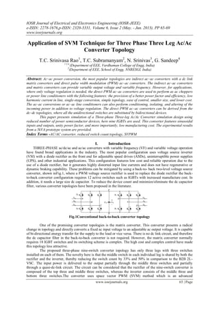
  • 1. IOSR Journal of Electrical and Electronics Engineering (IOSR-JEEE) e-ISSN: 2278-1676,p-ISSN: 2320-3331, Volume 6, Issue 2 (May. - Jun. 2013), PP 65-69 www.iosrjournals.org www.iosrjournals.org 65 | Page Application of SVM Technique for Three Phase Three Leg Ac/Ac Converter Topology T.C. Srinivasa Rao1 , T.C. Subramanyam2 , N. Srinivas3 , G. Sandeep4 1 3 4 (Department of EEE, Vardhaman College of Engg, India) 2 (Department of EEE, School of Engg, NNRESGI, India) Abstract: Ac–ac power conversion, the most popular topologies are indirect ac–ac converters with a dc link matrix converters and direct pulse width modulation (PWM) ac–ac converters. The indirect ac–ac converters and matrix converters can provide variable output voltage and variable frequency. However, for applications, where only voltage regulation is needed, the direct PWM ac–ac converters are used to perform as ac choppers or power line conditioners with the following features: the provision of a better power factor and efficiency, low harmonic current in line, single-stage conversion, simple topology, ease of control, smaller size, and lower cost. The ac–ac conversions or ac–ac line conditioners can also perform conditioning, isolating, and altering of the incoming power in addition to voltage regulation. The direct PWM ac–ac converters can be derived from the dc–dc topologies, where all the unidirectional switches are substituted by bidirectional devices. This paper presents simulation of a Three-phase Three-leg Ac/Ac Converter simulation design using reduced number of power semiconductor devices, here nine IGBTs are used. This converter features sinusoidal inputs and outputs, unity power factor, and more importantly, low manufacturing cost. The experimental results from a 5kVA prototype system are provided. Index Terms -AC/AC converter, reduced switch count topology, SVPWM I. Introduction THREE-PHASE ac/dc/ac and ac/ac converters with variable frequency (VF) and variable voltage operation have found broad applications in the industry. The most popular configuration uses voltage source inverter (VSI) with a diode rectifier as the front end for adjustable speed drives (ASDs), uninterruptible power supplies (UPS), and other industrial applications. This configuration features low cost and reliable operation due to the use of a diode rectifier, but it generates highly distorted input line currents and does not have regenerative or dynamic braking capability. These problems can be mitigated by using a back-to- back two-level voltage source converter, shown inFig.1, where a PWM voltage source rectifier is used to replace the diode rectifier the back- to-back converter configuration requires 12 active switches such as IGBTs with increased manufacture cost. In addition, it needs a large size dc capacitor. To reduce the device count and minimize/eliminate the dc capacitor filter, various converter topologies have been proposed in the literature. Fig.1Conventional back-to-back converter topology One of the promising converter topologies is the matrix converter. This converter presents a radical change in topology and directly converts a fixed ac input voltage to an adjustable ac output voltage. It is capable of bi-directional energy transfer for the supply to the load or vice versa. There is no dc link circuit, and therefore the dc capacitor filter in the back-to-back converter is not required. However, the matrix converter normally requires 18 IGBT switches and its switching scheme is complex. The high cost and complex control have made this topology less attractive. The proposed three-phase nine-switch converter topology has only three legs with three switches installed on each of them. The novelty here is that the middle switch in each individual leg is shared by both the rectifier and the inverter, thereby reducing the switch count by 33% and 50% in comparison to the B2B 2L- VSC. The input power is delivered to the output partially through the middle three switches and partially through a quasi-dc-link circuit. The circuit can be considered that the rectifier of the nine-switch converter is composed of the top three and middle three switches, whereas the inverter consists of the middle three and bottom three switches.The converter uses space vector PWM (SVM) method which is an advanced
  • 2. Application Of Svm Technique For Three Phase Three Leg Ac/Ac Converter Topology www.iosrjournals.org 66 | Page computation-intensive PWM method and is possibly the best among all the PWM techniques for variable- frequency drive applications. II. Space Vector Modulation The space vector PWM (SVM) method is an advanced computation-intensive PWM method and is possibly the best among all the PWM techniques for variable-frequency drive applications. Because of its superior performance characteristics, it has been finding wide speed applications in recent years. The desired three phase voltages at the output of the inverter could be represented by an equivalent vector V rotating in the counter clock wise direction as shown in Fig.3. The magnitude of this vector is related to the magnitude of the output voltage (Fig.4) and the time this vector takes to complete one revolution is the same as the fundamental time period of the output voltage. Fig.2Output voltage vector in the α-βplane Fig.3 Output line voltages in time domain Let us consider the situation when the desired line-to-line output voltage vector V is in sector 1 as shown in Fig.3. This vector could be synthesized by the pulse-width modulation (PWM) of the two adjacent SSV’s V1 (pnn) and V2 (ppn), the duty cycle of each being d1 and d2, respectively, and the zero vector V7(nnn) / V8(ppp) ) of duty cycle d0: d1V1 + d2V2 =V=m Vg ejθ ………………………..(1) d1 + d2 + d0=0 ………..…………….(2) Where, 0 ≤m ≤0.866, is the modulation index. This would correspond to a maximum line-to-line voltage of 1.0Vg, which is 15% more than conventional sinusoidal PWM as shown. Fig.4 Synthesis of the required output voltage vector in sector 1
  • 3. Application Of Svm Technique For Three Phase Three Leg Ac/Ac Converter Topology www.iosrjournals.org 67 | Page All SVM schemes and most of the other PWM algorithms use Eqns. (1) and (2) for the output voltage synthesis. The modulation algorithms that use non-adjacent SSV's have been shown to produce higher THD and/or switching losses and are not analyzed here, although some of them, e.g. hysteresis, can be very simple to implement and can provide faster transient response. The duty cycles d1, d2, and d0, are uniquely determined, and Eqns. (1) and (2) , the only difference between PWM schemes that use adjacent vectors is the choice of the zero vector(s) and the sequence in which the vectors are applied within the switching cycle. The degrees of freedom we have in the choice of a given modulation algorithm is: 1) The choice of the zero vector; whether we would like to use V7(ppp) or V8(nnn) or both, 2) Sequencing of the vectors 3) Splitting of the duty cycles of the vectors without introducing additional commutations. 2.1 Output voltages of three-phase inverter S1 through S6 are the six power transistors that shape the output voltages When an upper switch is turned on (i.e., a, b or c is “1”), the corresponding lower switch is turned off (i.e., a', b' or c' is “0”). Eight possible combinations of on and off patterns for the three upper transistors (S1, S3, S5) Line to line voltage vector [Vab Vbc Vca]t --- (3) Line to neutral (phase) voltage vector [Van Vbn Vcn]t --------------(4) Table1. Tabulation of Output voltages of three-phase inverter 2.2 Basic switching vectors and Sectors  6 active vectors (V1,V2, V3, V4, V5, V6) 1. Axes of a hexagonal. 2. DC link voltage is supplied to the load. 3. Each sector (1 to 6): 60 degrees.  Two zero vectors (V0, V7) 1. At origin 2. No voltage is supplied to the load
  • 4. Application Of Svm Technique For Three Phase Three Leg Ac/Ac Converter Topology www.iosrjournals.org 68 | Page III. Nine-Switch Converter Topology Fig.5 shows the proposed three-phase nine- switch converter topology. This converter has three legs with three switches per leg. The novelty of this converter is that the middle switch in each of the three converter legs is shared by the rectifier and inverter, thereby reducing the switch count by 33% and 50% in comparison to the back-to-back converter and matrix converter, respectively. The input power is delivered to the output partially through the middle three switches and partially through a quasi dc link circuit. For the convenience of discussion, we can consider that the rectifier of the nine-switch converter is composed of top three and middle three switches. Fig.5 proposed three-phase nine- switch converter topology IV. Simulation Analysis The performance of the proposed nine-switch converter topology is simulated by simulink software. The utility supply is rated 208V and 60Hz with a supply inductance of L= 2.5mH. The converter is loaded with a three phase RL load of Rs=8 ohms and L= 2.5mH. The dc capacitor Cdl is 2350 µF. The rectifier is controlled by a vector control scheme with unity power factor operation. The inverter output voltage is not detected and therefore is not tightly controlled. The switching frequency of both rectifier and inverter is 3240Hz.Both CF and VF modes of operation are investigated. Fig.6Three phase Input voltage Fig7. Three phase input Current Fig8. Rectifier Line current(Ix) Fig9. Pulses to IGBTS Fig10. Inverter Output current(Ix)
  • 5. Application Of Svm Technique For Three Phase Three Leg Ac/Ac Converter Topology www.iosrjournals.org 69 | Page Fig11.Inverter output voltage(vxy) V. Conclusion A novel nine-switch PWM ac/ac converter topology using SVM technique was proposed in this paper. The topology uses only nine IGBT devices for ac to ac conversion through a quasi dc-link circuit. Compared with the conventional back-to-back PWM VSC using 12 switches and the matrix converter that uses 18, the number of switches in the proposed converter is reduced by 33% and 50%, respectively. The proposed converter features sinusoidal inputs and outputs, unity input power factor, and low manufacturing cost. The operating principle of the converter was elaborated, and modulation schemes for constant and VF operations were developed. Simulation results including a semiconductor loss analysis was provided, which reveal that the proposed converter, while working in CF mode, has an overall higher efficiency than the B2B 2L-VSC at the expense of uneven loss distribution. However, the VF-mode version requires IGBT devices with higher ratings and dissipates significantly higher losses, and thus, is not as attractive as its counterpart. Experimental verification is carried out on a 5-kVA prototype system. This paper analyzed the Back to Back inverter topology, and the more complex three-phase-leg topologies with the modulation concepts and derived carrier-based reference equations verified in simulation for all presented voltage-type -source inverters, and experimentally for a three-phase-leg -source inverter. The paper presents the Three-phase Three-leg Ac/Ac converter topology using Space vector Modulation technique for IGBT pulses. Experiments have been carried out to verify the validity of the proposed scheme. Reference [1] B . Wu, High-power Converters and AC Drives. Piscatawa y, NJ:IEEE/Wiley, 2006. [2] B . Singh, B. N. Singh, A. Chandra, K. Al-Haddad, A. Pandey, and D. P. Ko thari, “A review of three-phase improved p ower quality AC – DC converters,” IEEE Trans. I nd. Electron., vol. 51, no. 3, pp. 641–660, Jun. 2004. [3] F. B laabjerg, S. Frey sson, H. H. Hansen, and S. Hansen, “A new op-timized space-vector m odulation strategy for a component- minimized vo ltage source inverter,” IEEE Trans. Power Electron., vol. 12, no. 4, pp. 704–714, Jul. 1997. [4] R . L. A. R ibeiro, C. B. Jacobina, E. R . C . d a Silva, and A. M. N. Lima, “AC/AC converter with four switch three phase structures,” in Proc. I EEE PESC , 1996, vol. 1, pp. 134–139. [5] K. Gi-Taek and T. A. Lipo, “VSI-PWM rectifier/inverter system with a reduced switch count,” IEEE Trans. Ind. Appl., vol. 32, no. 6, pp. 1331– 1337, Nov./Dec. 1996. [6] A. B ouscayrol, B. Francois, P. Delarue, and J. Niiranen, “Control imple- mentation o f a five-leg AC–AC converter to supply a three-phase induction machine,” IEEE Trans. Power Electron., vol. 20, no. 1, pp. 107–115, Jan. 2005. [7] C. B. Jacobina, I. S. de Freitas, E. R. C. da Silva, A. M. N. Lima, and R. L. A. Ribeiro, “Reduced switch count DC-link AC–AC five- leg converter,”IEEE Trans. Power Electron., vol. 21, no. 5, pp. 1301–1310, Sep. 2006. [8] C. B. Jacobina, I. S. de Freitas, and A. M. N. Lima, “DC-link three-phaseto- three-phase four-leg converters,” IEEE Trans. Ind. Electron., vol. 54, no. 4, pp. 1953–1961, Aug. 2007. [9] J. Minibock and J. W. Kolar, “Novel concept for mains voltage proportional input current shaping of a VIENNA rectifier eliminating controller multipliers,” IEEE Trans. Ind. Electron., vol. 52, no. 1, pp. 162–170, Feb. 2005. [10] T. Nussbaumer, M. Baumann, and J.W. Kolar, “Comprehensive design of a three-phase three-switch buck-type PWM rectifier,” IEEE Trans. Power Electron., vol. 22, no. 2, pp. 551–562, Mar. 2007. [11] F. A. B. Batista and I. Barbi, “Space vector modulation applied to threephase three-switch two-level unidirectional PWMrectifier,” IEEE Trans. Power Electron., vol. 22, no. 6, pp. 2245–2252, Nov. 2007. [12] P. W. Wheeler, J. Rodriguez, J. C. Clare, L. Empringham, and A. Weinstein, “Matrix converters: A technology review,” IEEE Trans.Ind. Electron., vol. 49, no. 2, pp. 276–288, Apr. 2002. [13] L.Wei, T. A. Lipo, andH.Chan, “Matrix converter topologies with reduced number of switches,” in Proc. IEEE PESC, 2002, vol. 1, pp. 57–63. [14] J.W. Kolar, F. Schafmeister, S. D. Round, and H. Ertl, “Novel three-phase AC–AC sparse matrix converters,” IEEE Trans. Power Electron., vol. 22, no. 5, pp. 1649–1661, Sep. 2007.